

Page 1
Register Online!
hatcocorp.com
(see page 2)
Installation and Operating Manual
Original Instructions
Originalanleitung
Instrucciones originales
Instructions originales
Istruzioni originali
Vertaling van de
originele instructies
THERM-MAX
Salamander
TMS Series
For and non- Models
P/N07.04.582.00
Salamander
Serien TMS
Installations- und Bedienungshandbuch
P 13
Registrieren Sie sich online!
Salamander
Séries TMS
Manuel d'installation et d'utilisation
P 35
S'inscrire en ligne!
Salamander
Modelreeksen TMS
Handleiding voor Installatie en Bediening
P 57
Registreer online!
Salamandra
Series TMS
Manual de Instalación y Operación
P 24
¡Regístrese en línea!
Fornello portatilei
Serie TMS
Manuale per l'installazione e l'uso
P 46
Registratevi online!
© 2015 Hatco Corporation
Page 2
CONTENTS
WARNING
NOTICE
CAUTION
Correct Disposal of this Product
This marking indicates that this product and its electronic
components should not be disposed of with other
commercial waste. To prevent possible harm to the
environment or human health from uncontrolled waste
disposal, recycle responsibly to promote the sustainable
reuse of material resources. To dispose of product and its
electronic components, contact supplier where product
was purchased for environmentally safe recycling.
Important Owner Information ..............................................2
Introduction...........................................................................2
Important Safety Information...............................................3
Model Description.................................................................4
Model Designation................................................................4
Specifications........................................................................5
Electrical Rating Chart ........................................................5
Dimensions .........................................................................5
Installation.............................................................................6
General ...............................................................................6
Countertop Installation ........................................................6
Wall Installation ...................................................................7
Electrical Connections.........................................................7
IMPORTANT OWNER INFORMATION
Record the model number, serial number, voltage, and
purchase date of the unit in the spaces below (located on the
side of the unit near the power inlet area). Please have this
information available when calling Hatco for service assistance.
Model No. ________________________________________
Serial No. ________________________________________
Voltage __________________________________________
Date of Purchase __________________________________
Register your unit!
Completing online warranty registration will prevent delay in
obtaining warranty coverage. Access the Hatco website at
www.hatcocorp.com, select the Parts & Service pull-down
menu, and click on “Warranty Registration”.
Operation...............................................................................8
General ...............................................................................8
Control Panel ......................................................................8
Operating the Salamander ..................................................9
Maintenance ........................................................................10
General .............................................................................10
Daily Cleaning ...................................................................10
Troubleshooting Guide.......................................................11
International Limited Warranty..........................................12
Service Information ............................................................12
Business
Hours: 7:00
Telephone: (414) 671-6350
E-mail: partsandservice@hatcocorp.com
Fax: (414) 671-3976 (Parts and Service)
Additional information can be found by visiting our web site at
www.hatcocorp.com.
AM to 5:00 PM Central Standard Time (C.S.T.)
(Summer Hours: June to September—
7:00
AM to 5:00 PM C.S.T.
Monday through Thursday
7:00
AM to 4:00 PM C.S.T. Friday)
INTRODUCTION
Hatco’s THERM-MAX Salamanders are specially-designed for
cooking, grilling, reheating, and keeping foods hot. Their
unparalleled startup speed is a direct result of Hatco’s patented
“instant on” heating elements located in the upper housing of
each salamander. The two pairs of independently-controlled
heating elements provide for the benefits of flexibility and
energy conservation. Reduced transfer of heat to the
surrounding area and a versatile hold function on certain
models make the THERM-MAX Salamander energy efficient
and easy to operate.
Hatco THERM-MAX Salamanders are products of extensive
research and field testing. The materials used were selected
for maximum durability, attractive appearance, and optimum
performance. Every unit is inspected and tested thoroughly
prior to shipment.
This manual provides the installation, safety, and operating
instructions for THERM-MAX Salamanders. Hatco
recommends all installation, operating, and safety instructions
appearing in this manual be read prior to installation or
operation of a unit.
Sa
he
t
WARNING indicates a hazardous situation which, if not
avoided, could result in death or serious injury.
CAUTION indicates a hazardous situation which, if not
avoided, could result in minor or moderate injury.
NOTICE is used to address practices not related to personal
injury.
2
fol
owi
l
ng
s
gnal
i
word
panel
:
s
Form No. TMSCEM-0615
tifie
n
e
l is id
a
u
n
is ma
th
s in
r
a
e
p
p
t a
a
th
n
tio
ma
r
fo
ty in
fe
y
b
d
Page 3
IMPORTANT SAFETY INFORMATION
NOTICE
CAUTION
WARNING
WARNING
Read the following important safety information before using this equipment to avoid serious
injury or death and to avoid damage to equipment or property
.
ELECTRIC SHOCK HAZARD:
• Unit must be installed by a qualified electrician.
Installation must conform to all local electrical codes.
Installation by unqualified personnel will void unit
warranty and may lead to electric shock or burn, as well
as damage to unit and/or its surroundings.
• Units supplied without an electrical plug require field
installation of proper plug. Plug must be properly
grounded and of correct voltage, size, and
configuration for electrical specifications of unit.
Contact a qualified electrician to determine and install
proper electrical plug.
• Units supplied without an electrical cord and plug
require field installation of proper cord and plug or a
hardwired connection to on-site electrical system.
Connection must be properly grounded and of correct
voltage, size, and configuration for electrical
specifications of unit. Contact a qualified electrician to
determine and install proper electrical connection.
• When installing a hardwired unit, a 2-pole or 3-pole
switch (depending on unit) must be installed between
unit and main electrical supply. The switch must be
rated properly and have contacts with a minimum
opening distance of 3 mm (1/8″).
• Turn OFF power switch, unplug power cord/turn off
power at circuit breaker, and allow unit to cool before
performing any cleaning, adjustments, or maintenance.
• DO NOT submerge or saturate with water. Unit is not
waterproof. Do not operate if unit has been submerged
or saturated with water.
• Unit is not weatherproof. Locate unit indoors where
ambient air temperature is a minimum of 21°C (70°F)
and a maximum of 29°C (85°F).
• Do not steam clean or use excessive water on unit.
• This unit is not “jet-proof” construction. Do not use jetclean spray to clean this unit.
• Do not pull unit by power cord.
• Discontinue use if power cord is frayed or worn.
• Do not attempt to repair or replace a damaged power
cord. Cord must be replaced by Hatco, an Authorized
Hatco Service Agent, or a person with similar
qualifications.
• Do not clean unit when it is energized or hot.
• This unit must be serviced by qualified personnel only.
Service by unqualified personnel may lead to electric
shock or burn.
• Use only Genuine Hatco Replacement Parts when
service is required. Failure to use Genuine Hatco
Replacement Parts will void all warranties and may
subject operators of the equipment to hazardous
electrical voltage, resulting in electrical shock or burn.
Genuine Hatco Replacement Parts are specified to
operate safely in the environments in which they are
used. Some aftermarket or generic replacement parts
do not have the characteristics that will allow them to
operate safely in Hatco equipment.
Form No. TMSCEM-0615
FIRE HAZARD:
• Install unit on and around non-combustible surfaces
with non-combustible construction only. Ensure surface
construction has no combustible material against
underside. In all cases, such construction shall extend at
least 305 mm (12″) beyond equipment on all sides.
• Locate unit a minimum of 51 mm (2″) from any walls. If
safe distances are not maintained, discoloration or
combustion could occur.
• Do not obstruct air intake openings or air exhaust
openings on outer housing of unit. Unit combustion or
malfunction may occur.
• Do not place anything on top of unit.
For wall mounting, use special wall mount bracket
provided with unit only. Secure wall mount bracket to a
solid, non-combustible surface using appropriate hardware
for mounting surface and weight of unit.
Make sure all operators have been instructed on the safe
and proper use of the unit.
This unit is not intended for use by children or persons
with reduced physical, sensory, or mental capabilities.
Ensure proper supervision of children and keep them away
from the unit.
This unit has no “user-serviceable” parts. If service is
required on this unit, contact an Authorized Hatco Service
Agent or contact the Hatco Service Department at
414-671-6350; fax 414-671-3976.
BURN HAZARD:
• Some exterior surfaces on the unit will get hot. Use
caution when touching these areas.
• Plate/tray will be very hot upon removal — use oven
mitt, protective clothing, or pan gripper to remove.
Locate unit at proper counter height in an area that is
convenient for use. Location should be level to prevent unit
or its contents from falling accidentally and strong enough
to support the weight of the unit and contents.
Do not place anything on top of unit; doing so may subject
personnel to injury or damage unit.
Units are voltage-specific. Refer to specification label for
electrical requirements before beginning installation.
Do not lock ON timer knob. Unit has instant-on heating
elements designed to reach cooking temperatures quickly.
Locking ON timer knob will increase energy consumption
and may shorten life of heating elements.
Use non-abrasive cleaners and cloths only. Abrasive
cleaners and cloths could scratch finish of unit, marring its
appearance and making it susceptible to soil accumulation.
Clean unit daily to avoid malfunctions and maintain
sanitary operation.
3
Page 4
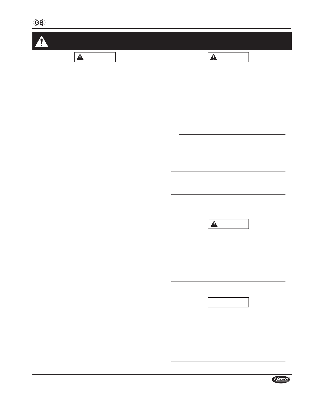
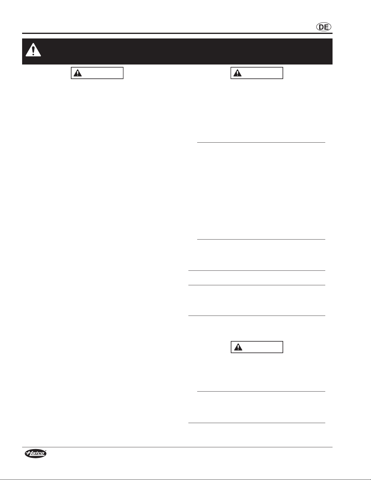
MODEL DESCRIPTION
Upper
Housing
Timer Knob
Cooking
Grate
Drip
Tray
Height
Gauge
Heating Mode
Selector
T M S - 1 H
THERM-MAX
Salamander
Capacity = Full-Size
Gastronorm Pan
H = COOK and HOLD Functions
No Character = COOK Function Only
All Models
Hatco’s THERM-MAX Salamander is specially-designed for
versatility in the kitchen with the capabilities to cook, grill,
reheat, and keep foods hot. The salamander is constructed of
stainless steel for easy cleaning and durability. The four highpowered heating elements are ready for use within 8 seconds.
Each pair of heating elements can be controlled independently
or together using the heating mode selector and timer knob
located on the control panel. The heating elements are
strategically positioned inside the moveable upper housing to
reduce the transfer of heat to the surrounding area. The HOLD
function on TMS-1H models is ideal for keeping foods hot or
reheating foods. A removeable cooking grate and drip tray
allows for easy cleanup. The unique features and flexibility of
the THERM-MAX Salamander make it easy to operate, energy
efficient, and highly functional in any kitchen.
Model TMS-1H
MODEL DESIGNATION
Model Designation
4
Form No. TMSCEM-0615
Page 5
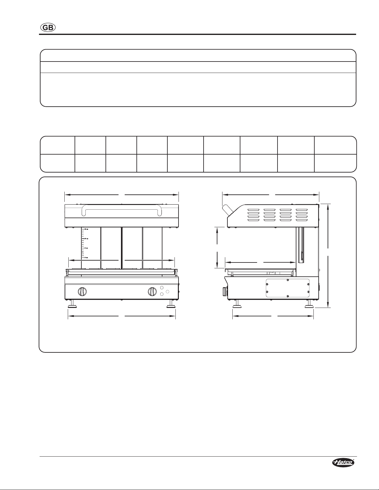
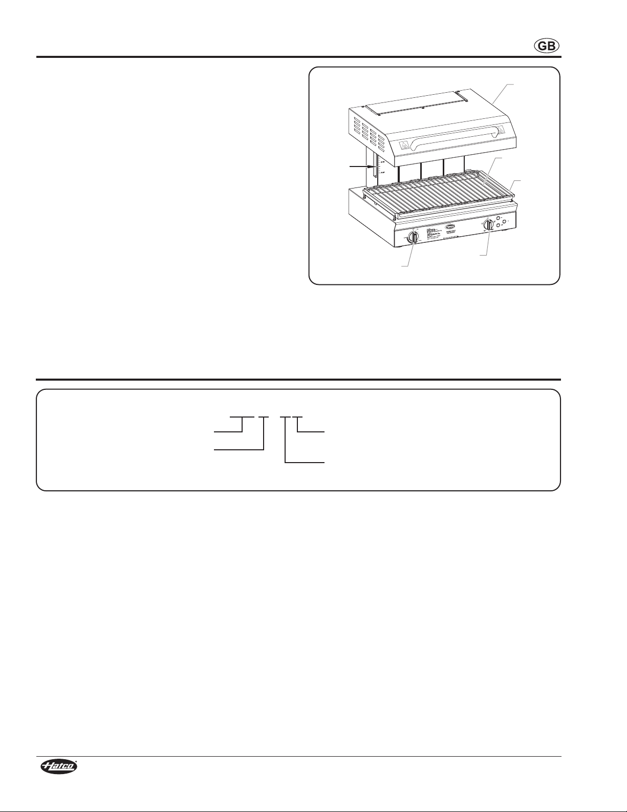
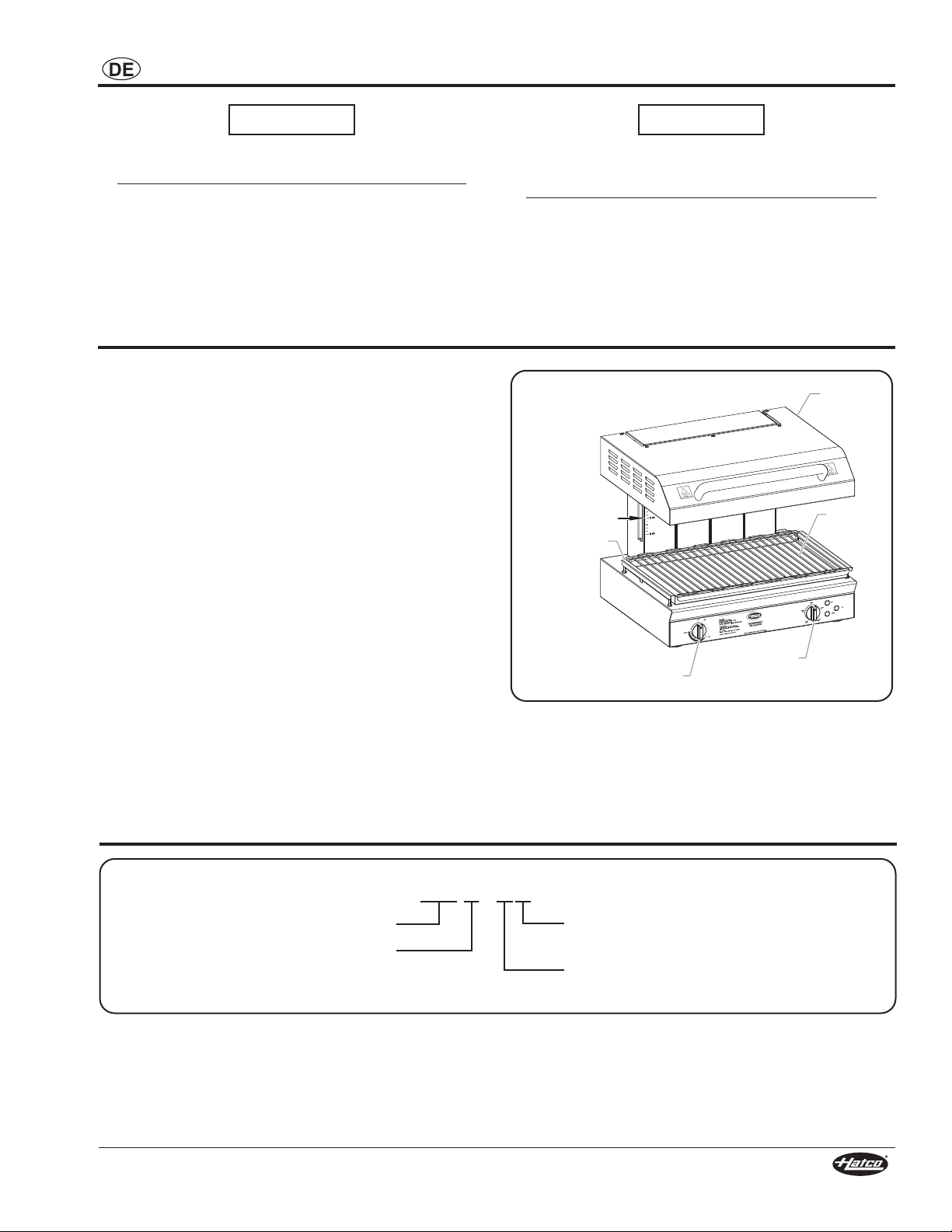
SPECIFICATIONS
Front View Side View
A
FFF
D E
G
C
H
B
Electrical Rating Chart
Model Voltage Hertz Phase Watts Amps Shipping Weight
TMS-1H
TMS-1
NOTE: Shipping weight includes packaging.
230 50/60 1 4000 17.4 72 kg (159 lbs.)
230 50/60 1
230/400 50/60 3
200 50/60 3
Dimensions
Model Width
TMS-1H and
TMS-1
(A)
600 mm
(23-5/8″)
Depth
(B)
510 mm
(20-1/8″)
Height
546 mm
(21-1/2″)
(C)
Footprint
Width (D)
520 mm
(20-1/2″)
4000 17.4
4000 8.7
4000 13.7
Footprint
Depth (E)
380 mm
(15″)
Cooking
Width (F)
540 mm
(21-1/4″)
Cooking
Depth (G)
365 mm
(14-5/16″)
72 kg (159 lbs.)
72 kg (159 lbs.)
72 kg (159 lbs.)
Cooking
Height (H)
50 to 212 mm
(2″ to 8-1/4″)
Form No. TMSCEM-0615
5
Page 6
INSTALLATION
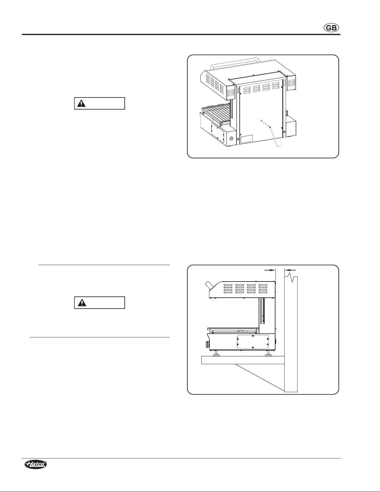
WARNING
CAUTION
Transport Locking
Screw
Wall
Countertop
51 mm (2″)
General
THERM-MAX Salamanders are shipped with most components
pre-assembled. Care should be taken when unpacking the
shipping carton to avoid damage to the unit and the
components enclosed. The salamander can be placed on a
countertop or mounted to a brick or cement wall. The following
installation instructions must be performed before operating the
salamander.
ELECTRIC SHOCK HAZARD:
• Unit must be installed by a qualified electrician.
Installation must conform to all local electrical codes.
Installation by unqualified personnel will void unit
warranty and may lead to electric shock or burn, as well
as damage to unit and/or its surroundings.
• Unit is not weatherproof. Locate unit indoors where
ambient air temperature is a minimum of 21°C (70°F)
and a maximum of 29°C (85°F).
FIRE HAZARD:
• Install unit on and around non-combustible surfaces
with non-combustible construction only. Ensure
surface construction has no combustible material
against underside. In all cases, such construction
shall extend at least 305 mm (12″) beyond equipment
on all sides.
• Locate unit a minimum of 51 mm (2″) from any walls. If
safe distances are not maintained, discoloration or
combustion could occur.
• Do not obstruct air intake openings or air exhaust
openings on outer housing of unit. Unit combustion or
malfunction may occur.
• Do not place anything on top of unit.
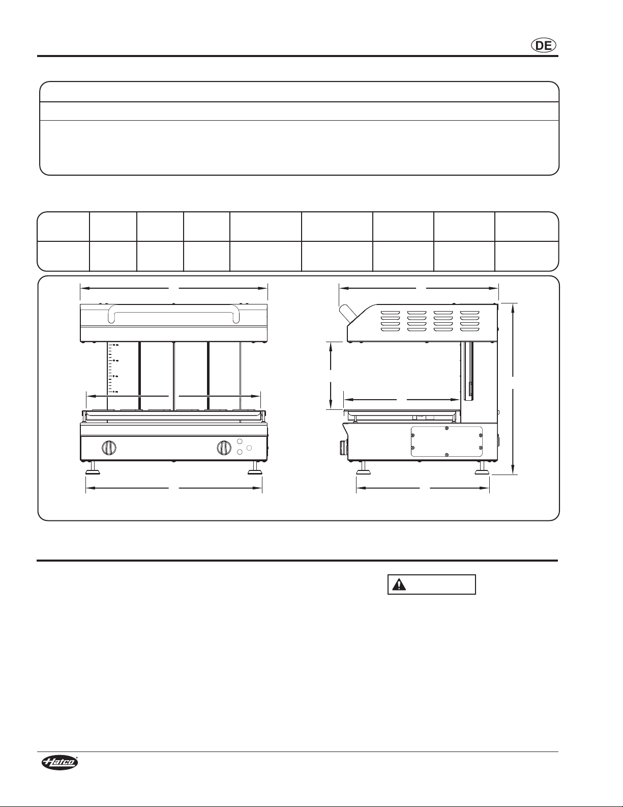
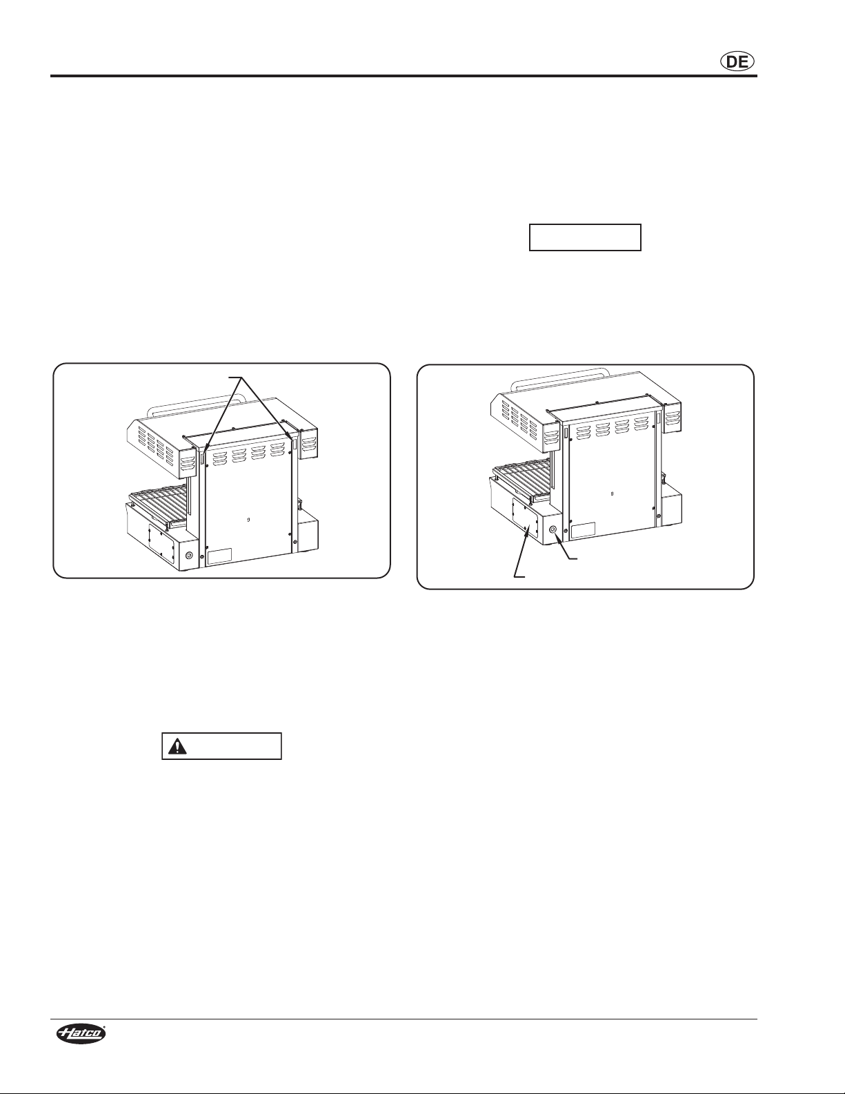
4. Remove the transport locking screw used to secure the
upper housing during shipping. Discard the screw.
Transport Locking Screw
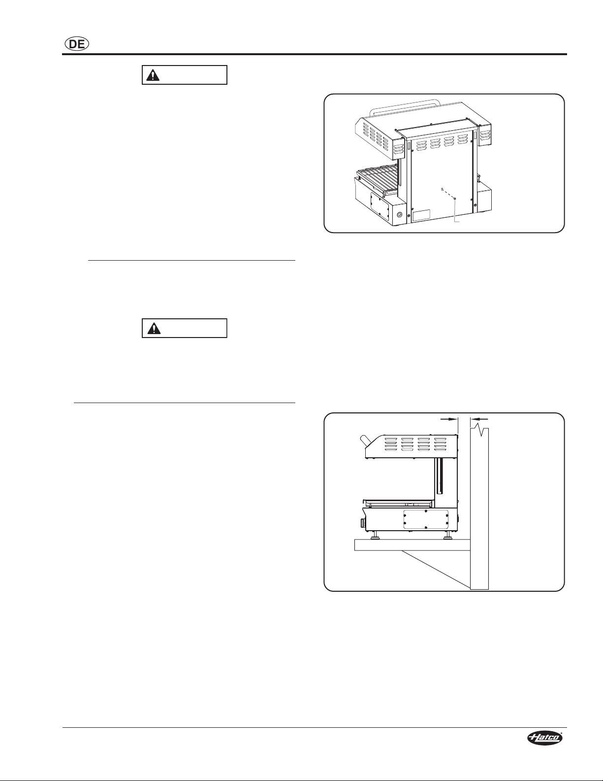
Countertop Installation
1. Place the unit in the desired location.
• Locate the unit directly underneath an exhaust hood if
possible. This will ensure total suction of steam
produced during cooking.
• Make sure the unit is at the proper height in an area
convenient for use.
• Make sure the countertop is level and strong enough to
support the weight of the unit and food product.
• Make sure all the feet on the bottom of the unit are
positioned securely on the countertop with a minimum
of 51 mm (2″) between the unit and any wall.
For wall mounting, use special wall mount bracket
provided with unit only. Secure wall mount bracket to a
solid, non-combustible surface using appropriate hardware
for mounting surface and weight of unit.
Locate unit at proper counter height in an area that is
convenient for use. Location should be level to prevent unit
or its contents from falling accidentally and strong enough
to support the weight of the unit and contents.
Do not place anything on top of unit; doing so may subject
personnel to injury or damage unit.
NOTE: A qualified person must check possible placements of
NOTE: To prevent delay in obtaining warranty coverage,
the salamander to ensure that the proper electrical
supply line is available.
1. Remove the unit from the shipping carton.
complete online warranty registration. See the
IMPORTANT OWNER INFORMATION section for details.
2. Remove tape and protective packaging from all surfaces
of unit.
3. Clean the unit thoroughly to remove all protective industrial
grease. NOTICE: Use non-abrasive cleaners and cloths
only.
Minimum Distance Requirement
2. Level the unit by turning the leveling feet on each leg, if
necessary. When looking at the bottom of the unit, turning
the feet counterclockwise will lengthen the legs, and turning
the feet clockwise will shorten the legs.
3. Have a qualified electrician perform the necessary electrical
connections (refer to “Electrical Connections” in this section
for additional information).
6
Form No. TMSCEM-0615
Page 7
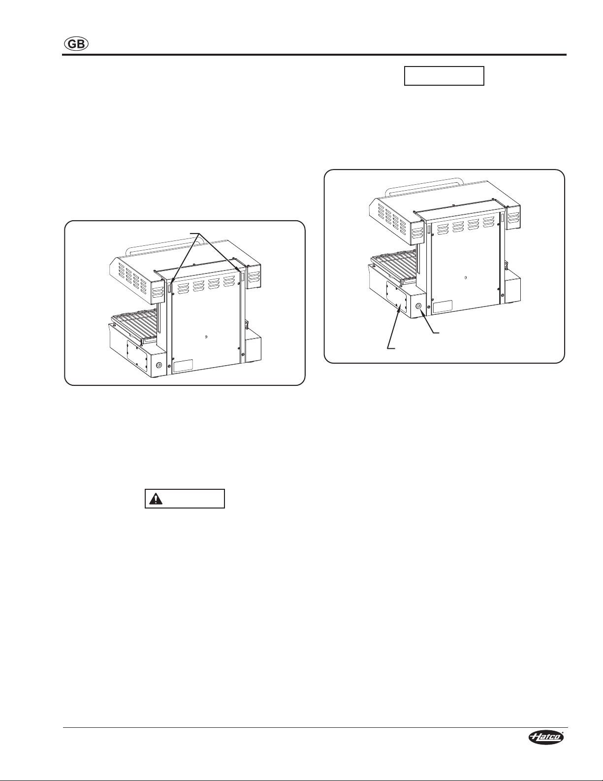
Wall Installation
Mounting Slots
WARNING
Power Inlet
Access Panel
NOTICE
1. Install the wall mount bracket provided with the unit onto a
solid, non-combustible surface using the appropriate
fasteners. There are five mounting holes on the wall mount
bracket.
• Make sure the fasteners are appropriate for the
installation surface and the weight of the unit.
• Locate the unit directly underneath an exhaust hood if
possible. This will ensure total suction of steam
produced during cooking.
• Make sure the unit is at the proper height in an area
convenient for use.
2. Align the mounting slots on the back of the unit with the
hooks on the wall mount bracket. Set the unit on the hooks.
INSTALLATION
Make sure electrical supply matches the voltage and
frequency rating on the specification label. Incorrect
electrical supply may damage the unit.
Hardwired Connection
1. Remove the access panel to expose the power inlet area of
the unit. It is located on the right rear side of the unit when
facing the controls.
3. Have a qualified electrician perform the necessary electrical
Electrical Connections
The THERM-MAX Salamander must be hardwired to the
electrical supply or have the appropriate cord and/or plug
installed.
ELECTRIC SHOCK HAZARD:
• Units supplied without an electrical plug require field
• Units supplied without an electrical cord and plug
• When installing a hardwired unit, a 2-pole or 3-pole
• Unit must be connected to an equipotential system that
Form No. TMSCEM-0615
Mounting Slots on Back of Unit
connections (refer to “Electrical Connections” in this section
for additional information).
installation of proper plug. Plug must be properly
grounded and of correct voltage, size, and
configuration for electrical specifications of unit.
Contact a qualified electrician to determine and install
proper electrical plug.
require field installation of proper cord and plug or a
hardwired connection to on-site electrical system.
Connection must be properly grounded and of correct
voltage, size, and configuration for electrical
specifications of unit. Contact a qualified electrician to
determine and install proper electrical connection.
switch (depending on unit) must be installed between
unit and main electrical supply. The switch must be
rated properly and have contacts with a minimum
opening distance of 3 mm (1/8″).
complies with the latest electrical standards.
Location of Power Inlet
2. Locate the terminal block inside the unit.
3. Bring power leads from a properly sized circuit breaker or
disconnect switch through the power inlet on the unit.
4. Make the appropriate connections.
• Use copper wire only.
• Tighten connections to a minimum of 4.25 newton
meters (40 inch pounds).
• A grounding screw is provided near the electrical
terminals. An equipment grounding conductor must be
properly connected to it.
5. Replace and secure the access panel.
Cord and Plug Connection
On units supplied with a power cord, connect the proper plug to
the cord. Make sure the plug is rated for the specific load and
the plug matches a suitable receptacle.
NOTE: The specification label is located on the side of the unit
near the power inlet. See the label for verification of unit
electrical information.
NOTE: The plug and receptacle must be grounded in
accordance with current standards.
7
Page 8
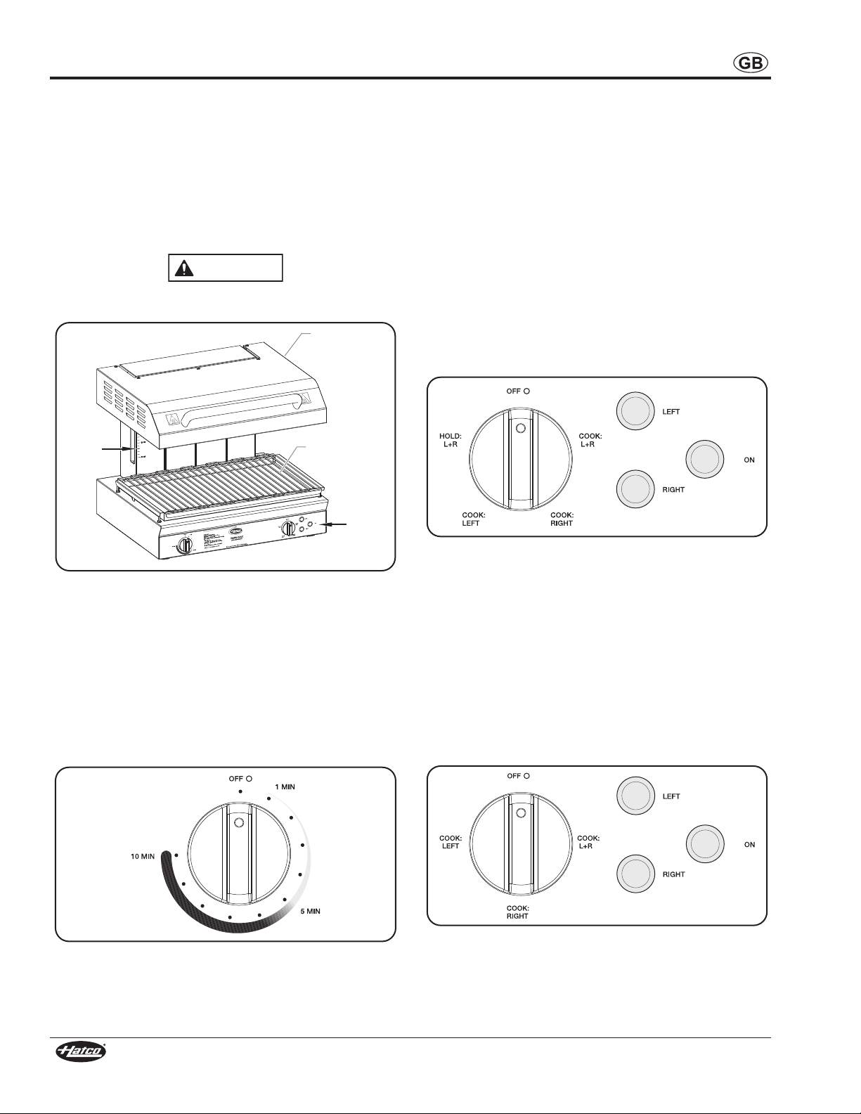
OPERATION
WARNING
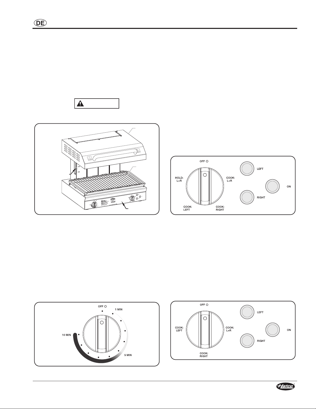
Upper
Housing
Cooking
Grate
Control
Panel
Height
Gauge
General
The THERM-Max Salamander is equipped with two main
functions, COOK and HOLD. On both models, the COOK
function uses the full intensity of the overhead, “instant on”
heating elements to cook food. On TMS-1H models, the HOLD
function operates the overhead heating elements at a lower
intensity to maintain the cooking temperature reached during
the cooking cycle.
Use the following information and procedures to operate the
THERM-MAX Salamander.
Read all safety messages in the IMPORTANT SAFETY
INFORMATION section before operating this equipment.
Heating Mode Selector
The heating mode selector determines the function of the
overhead elements in the salamander. The operation of this
knob is slightly different for each model.
TMS-1H Models
The heating mode selector on TMS-1H models has five
positions and two functions — COOK and HOLD. The following
are descriptions of the five positions:
OFF — No elements selected. The elements will not heat when
the timer knob is turned on.
COOK: L+R — Selects both pairs of elements for cooking.
COOK: RIGHT — Selects the pair of elements on the right side
of the salamander for cooking.
COOK: LEFT — Selects the pair of elements on the left side of
the salamander for cooking.
HOLD: L+R — Energizes both pairs of elements for holding.
Components
Control Panel
The following are descriptions of the controls used to operate
the THERM-MAX Salamanders. All controls are located on the
control panel at the front of the unit.
Timer Knob
The timer knob is used to set the timer for the desired COOK
time from 1 MIN to 10 MIN (one to ten minutes) . When the
timer knob is in the OFF position, the elements are disabled for
the COOK function. Turning the timer knob clockwise energizes
the selected elements for the desired amount of COOK time.
Timer Knob
Model Heating Mode Selector and Indicator Lights
TMS-1 Models
The heating mode selector on TMS-1 models has four positions
and one function — COOK. The following are descriptions of
the four positions:
OFF — No elements activated. The elements will not heat when
the timer knob is turned on.
COOK: L+R — Selects both pairs of elements for cooking.
COOK: RIGHT — Selects the pair of elements on the right side
of the salamander for cooking.
COOK: LEFT — Selects the pair of elements on the left side of
the salamander for cooking.
TMS-1 Model Heating Mode Selector and Indicator Lights
8
Form No. TMSCEM-0615
Page 9
OPERATION
NOTICE
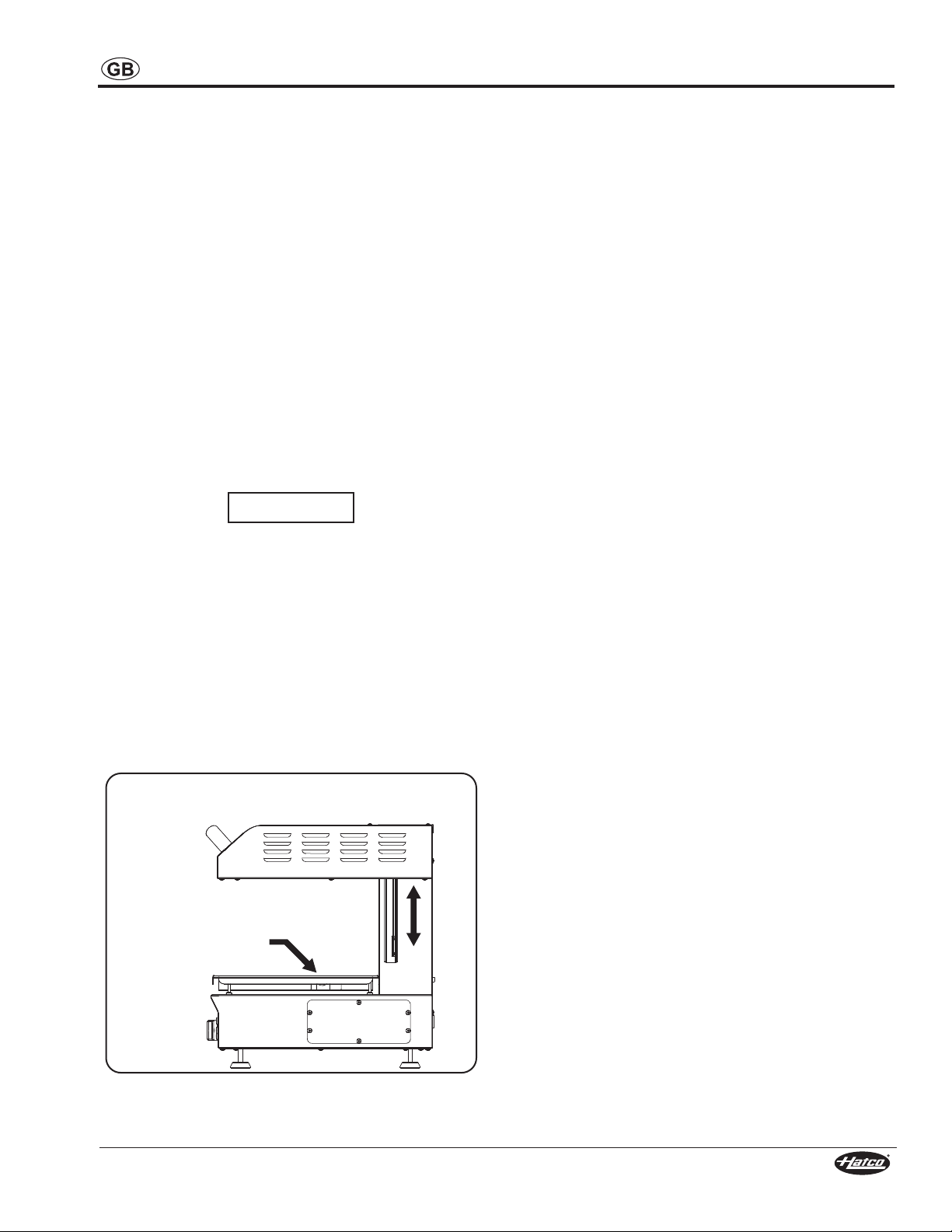
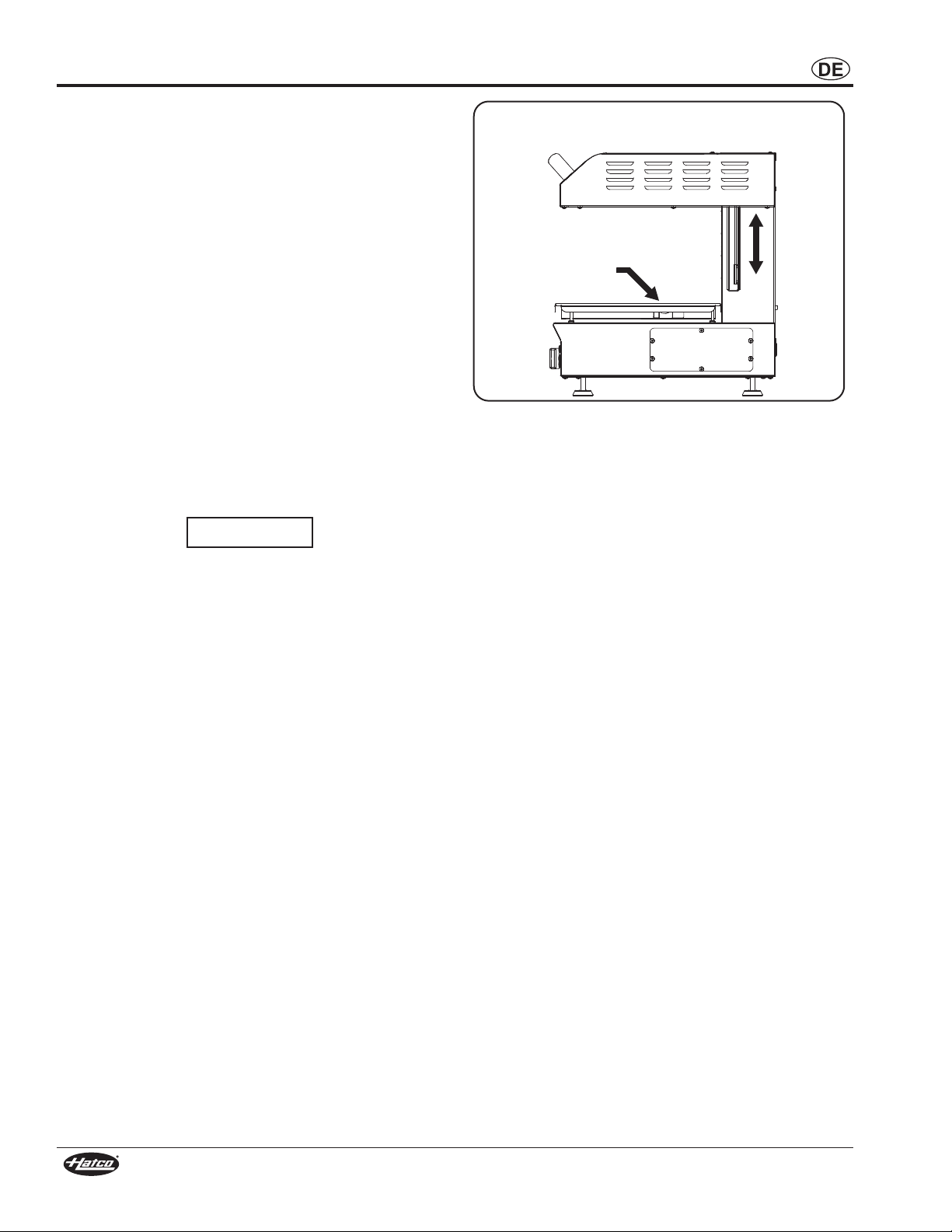
Place food product
onto cooking grate.
Lower upper housing to
increase heat intensity,
raise to decrease.
Indicator Lights
There are three indicators lights on the control panel:
LEFT Indicator Light — Illuminates when the timer knob is
active and the left pair of overhead elements are selected for
heating.
RIGHT Indicator Light — Illuminates when the timer knob is
active and the right pair of overhead elements are selected for
heating.
ON Indicator Light — Illuminates when the heating mode
selector is turned to any COOK or HOLD function.
Operating the Salamander
COOK Function
During the COOK function, the overhead heating elements
operate at full power/intensity to ensure heat is evenly
dispersed over the cooking surface. The intensity of the
temperature can be adjusted by raising or lowering the upper
housing or by using only one pair of heating elements instead
of all four. The intensity of the heat that penetrates the food
decreases as the distance between the food and the heating
elements increases. Use the following procedure to operate the
salamander in the COOK function.
Do not lock ON timer knob. Unit has instant-on heating
elements designed to reach cooking temperatures quickly.
Locking ON timer knob will increase energy consumption
and may shorten life of heating elements.
1. Move the upper housing to the desired cooking height.
2. Place food product onto the cooking grate.
3. Turn the heating mode selector to the desired COOK
function.
• The ON indicator light will illuminate.
4. Turn the timer knob clockwise to the desired cooking time.
• The appropriate LEFT and/or RIGHT indicator light(s)
will illuminate to indicate which elements are selected
and heating.
5. When time expires, an audible “beep” signal will indicate that
the COOK cycle is complete. The heating elements will turn
off and the LEFT and/or RIGHT indicator light(s) will turn off.
NOTE: The operator can adjust the timer setting and turn the
heating element(s) on or off at any time during operation
of the unit.
6. When cooking is complete, turn the heating mode selector
to the OFF (O) position. All indicator lights will turn off.
HOLD Function (TMS-1H models only)
When using the HOLD function, the overhead heating elements
operate at 25% of their maximum power/intensity to maintain
the cooking temperature reached during the cooking cycle.
1. Move the upper housing to the desired holding height.
2. Turn the heating mode selector to the HOLD L+R position.
• The LEFT and RIGHT indicator lights will illuminate to
indicate they are selected and heating.
• The ON indicator light will illuminate.
3. When holding is complete, turn the heating mode selector to
the OFF (O) position. The heating elements will turn off and
all indicator lights will turn off.
Form No. TMSCEM-0615
Operating the Salamander
9
Page 10
MAINTENANCE
WARNING
NOTICE
General
The THERM-MAX Salamander is designed for maximum
durability and performance with minimum maintenance.
ELECTRIC SHOCK HAZARD:
• Turn OFF power switch, unplug power cord/turn off
power at circuit breaker, and allow unit to cool before
performing any cleaning, adjustments, or maintenance.
• DO NOT submerge or saturate with water. Unit is not
waterproof. Do not operate if unit has been submerged
or saturated with water.
• Do not steam clean or use excessive water on unit.
• This unit is not “jet-proof” construction. Do not use jetclean spray to clean this unit.
• Do not clean unit when it is energized or hot.
• Use only Genuine Hatco Replacement Parts when
service is required. Failure to use Genuine Hatco
Replacement Parts will void all warranties and may
subject operators of the equipment to hazardous
electrical voltage, resulting in electrical shock or burn.
Genuine Hatco Replacement Parts are specified to
operate safely in the environments in which they are
used. Some aftermarket or generic replacement parts
do not have the characteristics that will allow them to
operate safely in Hatco equipment.
This unit has no “user-serviceable” parts. If service is
required on this unit, contact an Authorized Hatco Service
Agent or contact the Hatco Service Department at
414-671-6350; fax 414-671-3976.
Daily Cleaning
To preserve the finish of the unit as well as maintain
performance, it is recommended that the unit be cleaned daily.
Use non-abrasive cleaners and cloths only. Abrasive
cleaners and cloths could scratch finish of unit, marring
its appearance and making it susceptible to soil
accumulation.
Clean unit daily to avoid malfunctions and maintain
sanitary operation.
1. Turn off the unit, disconnect from the power supply, and
allow the unit to cool.
2. Remove the cooking grate and drip tray, and clean
thoroughly.
3. Wipe all metal surfaces using warm water, a mild
detergent, and a non-abrasive cloth. Stubborn stains may
be removed by using stainless steel wool and rubbing in
the direction of the satin finish.
4. Rinse the unit thoroughly using a cloth dampened with
warm water only.
5. Dry the unit using a clean, dry, and non-abrasive cloth.
NOTE: If the unit is left unused for an extended period of time,
apply a thin, protective layer of Vaseline oil over all
stainless steel parts using a cloth. The area where the
unit is installed must be kept clean as well.
10
Form No. TMSCEM-0615
Page 11
TROUBLESHOOTING GUIDE
WARNING
WARNING
This unit must be serviced by qualified personnel only.
Service by unqualified personnel may lead to electric
shock or burn.
C
e
bl
n
U
n
U
Unit
ptom
m
Sy
t
a
e
H
.
t
a
e
h
o
n
t
u
b
,
”
On
“
d
e
n
r
u
t
t
i
p
o
N
e
m
Ti
t
a
e
.
h
g
u
o
n
e
t
o
h
t
o
n
t
i
all.
at
king
wor
not
H
Unit
Unit
Cir
Tim
uit
c
er
n
i
o
r
n
i
not
not
or
g
w
o
g
br
Proba
e
m
e
l
e
u
o
t
r
e
t
a
e
H
r
e
m
e
l
e
plugged
ned
ur
t
er
eak
Heat
c
e
f
e
d
s)
(
t
n
.
t
i
n
t
i
w
s
e
d
o
M
ct
e
f
e
d
)
s
(
t
n
in. P
on.
ipped.
r
t
ode swit
M
ELECTRIC SHOCK HAZARD: Turn OFF power switch,
unplug power cord/turn off power at circuit breaker, and
allow unit to cool before performing any cleaning,
adjustments, or maintenance.
on
ti
c
A
e
v
ti
c
orre
a
ct
o
f
elec
k
.
e
a
s
a
t
c
o
f
a
t
c
o
f
unit
w
t
e
an Aut
t
or
f
r
C
y
r
r
r
“O
ci
A
Au
n
s
a
t
h
.
A
n
s
a
Au
n
s
a
o
int
p
ON
rcu
o t
t
gent
as
C
s
ic
r
e
s
si
e
sis
t
s
i
al
ck
t
u
s
i
t
s
pr
ra
s
t b
i
ip,
r
o
h
a
t
o
h
a
t
o
h
a
t
oper
ti
ec
or
hor
tanc
ze
i
r
ce
n
onnec
c
rcu
ci
z
i
r
ce
n
z
i
r
e
c
n
g
n
ion
t
re
ontac
c
Hat
iz
e.
H
d
.
t
b
t
i
H
d
e
.
H
d
e
.
power
e
th
t
of
r. If ci
ke
a
t
or
f
co
ed Hat
o
c
t
a
ion
a
re
o
c
t
a
co
t
a
s
Sa
his
an A
as
o S
c
Se
or
f
r
ke
e
S
e
S
upply.
m
a
l
anual.
m
ut
is
s
er
v
r
pr
a
v
r
vi
r
n
a
rcu
hor
tanc
v
a
v
i
t
h
c
v
i
h def
c
us
e
e
e
a
t
n
o
.
.
ve
i
t
c
e
f
e
d
.
e.
iv
ect
C
o
c
t
a
H
hec
C
g
a
t
l
vo
s
e
c
e
n
a
t
n
o
C
co
t
a
H
a
t
n
o
C
o
c
t
a
H
lug
e
vi
Re
RATI
OPE
se
Re
inues
cont
ic
v
er
S
Contac
o
c
Hat
Ag
e
c
i
oper
re
d
n
Ag
e
c
i
Ag
ce
r”
e
d
t b
i
ized Hat
e.
gent
e A
ic
n
e
upply
s
se
n
e
n
e
n
i
a
re
t
t
,
t
t
th
ke
o
i
o
o
c
or
r
f
r
r
e
r
o
Troubleshooting Questions?
If you continue to have problems resolving an issue, please contact the nearest Authorized Hatco Service Agency or Hatco for
assistance. To locate the nearest Service Agency, log onto the Hatco website at www.hatcocorp.com and click on
Find Service Agent, or contact the Hatco Parts and Service Team at:
Telephone: 414-671-6350
e-mail: partsandservice@hatcocorp.com
Fax: 414-671-3976
Form No. TMSCEM-0615
11
Page 12

INTERNATIONAL LIMITED WARRANTY
1. PRODUCT WARRANTY
Hatco warrants the products that it manufactures (the
“Products”) to be free from defects in materials and
workmanship, under normal use and service, for a period of one
(1) year from the date of purchase when installed and
maintained in accordance with Hatco’s written instructions or
18 months from the date of shipment from Hatco. Buyer must
establish the Product’s purchase date by registering the Product
with Hatco or by other means satisfactory to Hatco in its sole
discretion.
Hatco warrants the following Product components to be free
from defects in materials and workmanship from the date of
purchase (subject to the foregoing conditions) for the period(s)
of time and on the conditions listed below:
a) Two (2) Year Parts Warranty:
Conveyor Toaster Elements (metal sheathed)
Drawer Warmer Elements (metal sheathed)
Drawer Warmer Drawer Rollers and Slides
Strip Heater Elements (metal sheathed)
Display Warmer Elements (metal sheathed air heating)
Holding Cabinet Elements (metal sheathed air heating)
Heated Well Elements — HW and HWB Series
(metal sheathed)
b) Five (5) Year Parts Warranty:
3CS and FR Tanks
c) Ten (10) Year Parts Warranty:
Electric Booster Heater Tanks
Gas Booster Heater Tanks
d) Ninety (90) Day Parts Warranty:
Replacement Parts
THE FOREGOING WARRANTIES ARE EXCLUSIVE AND IN
LIEU OF ANY OTHER WARRANTY, EXPRESSED OR
IMPLIED, INCLUDING BUT NOT LIMITED TO ANY IMPLIED
WARRANTY OF MERCHANTABILITY OR FITNESS FOR A
PARTICULAR PURPOSE OR PATENT OR OTHER
INTELLECTUAL PROPERTY RIGHT INFRINGEMENT. Without
limiting the generality of the foregoing, SUCH WARRANTIES
DO NOT COVER: Coated incandescent light bulbs, fluorescent
lights, heat lamp bulbs, coated halogen light bulbs, halogen heat
lamp bulbs, xenon light bulbs, LED light tubes, glass
components, and fuses; Product failure in booster tank, fin tube
heat exchanger, or other water heating equipment caused by
liming, sediment buildup, chemical attack, or freezing; or Product
misuse, tampering or misapplication, improper installation, or
application of improper voltage.
2. LIMITATION OF REMEDIES AND DAMAGES
Hatco’s liability and Buyer’s exclusive remedy hereunder will be
limited solely to replacement of part or Product using, at Hatco’s
option, new or refurbished parts or Product by Hatco or a Hatcoauthorized service agency with respect to any claim made within
the applicable warranty period referred to above. Hatco reserves
the right to accept or reject any such claim in whole or in part.
In the context of this Limited Warranty, “refurbished” means a
part or Product that has been returned to its original
specifications by Hatco or a Hatco-authorized service agency.
Hatco will not accept the return of any Product without prior
written approval from Hatco, and all such approved returns shall
be made at Buyer’s sole expense. HATCO WILL NOT BE
LIABLE, UNDER ANY CIRCUMSTANCES, FOR
CONSEQUENTIAL OR INCIDENTAL DAMAGES, INCLUDING
BUT NOT LIMITED TO LABOR COSTS OR LOST PROFITS
RESULTING FROM THE USE OF OR INABILITY TO USE THE
PRODUCTS OR FROM THE PRODUCTS BEING
INCORPORATED IN OR BECOMING A COMPONENT OF ANY
OTHER PRODUCT OR GOODS.
SERVICE INFORMATION
The warranty on THERM-MAX Salamanders is for one year
from date of purchase or eighteen months from date of shipping
from Hatco, whichever occurs first.
If you experience a problem with a THERM-MAX Salamander
during the warranty period
Contact Local Hatco Dealer
When contacting the Hatco dealer for service assistance,
please supply the dealer with the following information to
ensure prompt processing:
• Model of unit
• Serial number (located on the side of the unit)
• Specific problem with the unit
• Date of purchase
• Name of business
• Shipping address
• Contact name and phone number
The Hatco dealer will do the following:
• Provide replacement part(s) as required
• Submit warranty claim to Hatco for processing
, please do the following:
Non-Warranty Problems
If you experience a non-warranty problem that requires
assistance, please contact the nearest Authorized Hatco
Service Agency.
To locate the nearest Service Agency:
• access our website at www.hatcocorp.com, select the
Resources pull-down menu, and click on “Find Service
Agent/Distributor”
• call Hatco Service at 414-671-6350
• e-mail Hatco Service at partsandservice@hatcocorp.com
12
Form No. TMSCEM-0615
Page 13
INHALT
WARNUNG
VORSICHT
HINWEIS
Ordnungsgemäße Entsorgung dieses Produkts
Dieses Symbol zeigt an, dass dieses Produkt und seine
elektronischen Komponenten nicht zusammen mit anderem
Gewerbeabfall entsorgt werden darf. Um Schädigungen der
Umwelt oder der menschlichen Gesundheit durch eine
unkontrollierte Entsorgung von Abfällen zu vermeiden, sollten
Sie es einer fachgerechten Entsorgung zuführen, um die
umweltverträgliche Wiederverwendung von Materialressourcen
zu fördern. Wenn Sie dieses Produkt und seine elektronischen
Komponenten entsorgen möchten, informieren Sie sich bitte
beim Händler, bei dem Sie es erworben haben, welche Möglichkeiten zu einer umweltfreundlichen Entsorgung bestehen.
Wichtige Informationen für den Benutzer ........................13
Einleitung ............................................................................13
Wichtige Sicherheitshinweise ...........................................14
Modellbeschreibung...........................................................15
Modellbezeichnung ............................................................15
Technische Daten ...............................................................16
Tabelle der elektrischen Anschlüsse.................................16
Abmessungen ...................................................................16
Aufstellen des Gerät...........................................................16
Allgemeines.......................................................................16
Installation auf der Arbeitsplatte........................................17
Installation an der Wand ...................................................18
Elektrische Anschlüsse .....................................................18
WICHTIGE INFORMATIONEN FÜR DEN BENUTZER
Schreiben Sie die Modellbezeichnung, die Seriennummer, die
Spannung und das Kaufdatum in die folgenden Zeilen (Plakette
mit den Spezifikationen befindet sich an der Seite des Geräts
in der Nähe des Netzeingangs). Haben Sie bitte dies
Information zur Hand, wenn Sie Hatco wegen einer ServiceUnterstützung anrufen.
Modellbezeichnung
Seriennummer
Spannung
Kaufdatum
________________________________________
________________________________________
________________________________
____________________________________
Betrieb .................................................................................19
Allgemeines.......................................................................19
Bedienfeld .........................................................................19
Bedienung des Salamander..............................................20
Wartung ...............................................................................21
Allgemeines.......................................................................21
Tägliche Reinigung ...........................................................21
Richtlinien zur Störungsbeseitigung ................................22
Internationale Beschränkte Garantie ................................23
Hinweise zur Garantieleistung ..........................................23
Geschäftszeiten: 7.00 Uhr bis 17.00 Uhr
Central Standard Time (CST)
(im Sommer: Juni bis September –
7.00 Uhr bis 17.00 Uhr (CST)
Montag bis Donnerstag
7.00 Uhr bis 16.00 Uhr (CST) Freitag)
Telefon: (414) 671-6350
E-mail: partsandservice@hatcocorp.com
Fax: (414) 671-3976 (Ersatzteile und Service)
Weitere Informationen finden Sie auf unserer Website unter
www.hatcocorp.com.
Registrieren Sie Ihr Gerät!
Wenn Sie die Online-Garantieregistrierung ausfüllen,
vermeidet das Verzögerungen beim Erhalt der
Garantiedeckung. Rufen Sie die Hatco Website unter
www.hatcocorp.com auf, wählen Sie das Pulldown-Menü
„Parts & Service“ (Ersatzteile und Wartung) aus und klicken
Sie auf „Warranty Registration“ (Garantieregisrtierung).
Die THERM-MAX Salamander von Hatco wurden speziell zum
Kochen, Grillen, Aufwärmen und Warmhalten von Speisen
entwickelt. Die unvergleichliche Einschaltgeschwindigkeit ist
ein Resultat der patentierten, sofort einschaltenden
Heizelemente von Hatco, die sich im oberen Gehäuse jedes
Salamander befinden. Die zwei Paar unabhängig voneinander
gesteuerten Heizelemente sorgen für Flexibilität und sparen
gleichzeitig Energie. Durch reduzierten Wärmeverlust an die
Umgebung und eine vielseitige Warmhaltefunktion an
bestimmten Modellen ist der THERM-MAX Salamander ein
energieeffizientes und leicht zu bedienendes Gerät.
Hatco THERM-MAX Salamander sind Produkte ausgiebiger
Forschung und Erprobung. Die verwendeten Werkstoffe
wurden gewählt, um maximale Lebensdauer, attraktives
Aussehen und optimale Leistung zu gewährleisten. Jedes
Gerät wird vor der Auslieferung gründlich inspiziert und
getestet.
Dieses Handbuch enthält die Anweisungen zu Aufstellung,
Sicherheit und Bedienung der THERM-MAX Salamander. Es
wird empfohlen, vor Aufbau und Inbetriebnahme eines Geräts
die Anweisungen zu Aufstellung, Sicherheit und Bedienung in
diesem Handbuch sorgfältig zu lesen.
Form-Nr. TMSCEM-0515
EINLEITUNG
u
d
ch
u
b
d
n
a
m H
se
ie
d
in
d
sin
ise
e
w
in
itsh
e
h
r
e
Sich
m
y
arns
W
WARNUNG bedeutet, dass eine Gefahr schwerer oder
tödlicher Verletzungen besteht, wenn die Situation nicht
vermieden wird.
VORSICHT bedeutet, dass eine Gefahr leichter oder
mittelschwerer Verletzungen besteht, wenn die Situation
nicht vermieden wird.
HINWEIS bedeutet, dass eine Gefahr von Geräte- oder
Sachschäden besteht.
13
bol
m
t
i
den fol
genden
S
gnal
i
wört
ern gek
ennz
r
ei
ch
c
e
hnet:
in
Page 14
WICHTIGE SICHERHEITSHINWEISE
VORSICHT
WARNUNG
WARNUNG
Vor der Anwendung dieser Ausrüstung lesen Sie die folgenden wichtigen
Sicherheitsinformationen, um ernste Verletzung oder Tod zu vermeiden und Schaden der
Ausrüstung oder des Eigentums zu vermeiden.
GEFAHR VON ELEKTROSCHOCKS:
• Das Gerät darf nur von einem qualifizierten Elektriker
installiert werden. Der Einbau muss alle örtlichen elektrischen
Vorschriften erfüllen. Bei Installation durch unqualifizierte
Personen erlischt die Garantie des Geräts und elektrischer
Schock oder Verbrennungen sowie Beschädigungen des
Geräts und/oder der Umgebung können die Folge sein.
• Bei Geräten ohne Stecker muss am Einsatzort ein
entsprechender Stecker montiert werden. Die Stecker müssen
ordnungsgemäß geerdet sein und die für die elektrischen
Daten des Geräts richtige Spannung, Größe und Konfiguration
haben. Setzen Sie sich mit einem qualifizierten Elektriker in
Verbindung, um die richtige Steckerart festzustellen und zu
installieren.
• Geräte, die ohne Kabel und Stecker geliefert werden, müssen
am Einsatzort mit geeignetem Kabel und Stecker oder mit
einem fest verdrahteten Anschluss an das vorhandene
elektrische Leitungsnetz angeschlossen werden. Die
Anschlüsse müssen ordnungsgemäß geerdet sein und die für
die elektrischen Daten des Geräts richtige Spannung, Größe
und Konfiguration aufweisen. Setzen Sie sich mit einem
qualifizierten Elektriker in Verbindung, um den korrekten
elektrischen Anschluss festzustellen und zu installieren.
• Bei Installation eines fest verdrahteten Geräts muss ein 2poliger oder 3-poliger Schalter (je nach Gerät) zwischen dem
Gerät und der Hauptstromversorgung installiert werden. Der
Schalter muss die korrekten Nennwerte aufweisen und die
Öffnungen der Kontakte müssen einen Mindestabstand von 3
mm (1/8″) haben.
• Schalten Sie die Stromversorgung AUS, ziehen Sie das
Netzkabel aus der Steckdose/betätigen Sie den Netzschalter
und lassen Sie das Gerät abkühlen, bevor Sie es reinigen,
einstellen oder warten.
• Tauchen Sie das Gerät NICHT in Wasser und reinigen Sie das
Gerät NICHT mit übermäßig viel Wasser. Das Gerät ist nicht
wasserdicht. Es darf nicht betrieben werden, wenn es in
Wasser getaucht oder mit übermäßig viel Wasser gereinigt
wurde.
• Das Gerät ist nicht wetterbeständig. Stellen Sie das Gerät in
einem Innenbereich auf, in dem die Umgebungslufttemperatur
mindestens 21 °C (70 °F) und höchstens 29 °C (85 °F) beträgt.
• Reinigen Sie das Gerät nicht mit Dampf oder übermäßig viel
Wasser.
• Dieses Gerät ist nicht für direktes Absprühen mit einem
Wasserstrahl geeignet. Es darf nicht mit einem Sprühstrahl
gereinigt werden.
• Ziehen Sie das Gerät nicht am Kabel.
• Betreiben Sie das Gerät nicht, wenn das Netzkabel
durchgescheuert oder abgenutzt ist.
• Versuchen Sie nicht, ein beschädigtes Netzkabel zu reparieren
oder zu ersetzen. Das Kabel muss durch Hatco, einen
autorisierten Servicebetrieb oder einen qualifizierten
Techniker ersetzt werden.
• Reinigen Sie das Gerät nicht, wenn es sich in Betrieb befindet
oder heiß ist.
• Reparaturen am das Gerät dürfen nur von qualifiziertem
Personal durchgeführt werden. Von unqualifiziertem Personal
durchgeführte Reparaturen können zu Elektroschocks oder
Verbrennungen führen.
• Verwenden Sie bei der Reparatur von Hatco Geräten
ausschließlich Hatco Ersatzteile. Wenn Sie keine OriginalHatco-Ersatzteile verwenden, werden alle Garantien ungültig
und Sie setzen die Bediener der Geräte möglicherweise
gefährlichen elektrischen Spannungen aus, welche zu
Stromschlag oder Verbrennungen führen können. OriginalHatco-Ersatzteile sind für den sicheren Betrieb unter den
gegebenen Einsatzbedingungen ausgelegt. Manche Ersatzteile
anderer Hersteller oder Nachbauteile verfügen nicht über die
geforderten Eigenschaften und funktionieren nicht sicher in
Hatco Geräten.
BRANDGEFAHR:
• Installieren Sie das Gerät ausschließlich an und in der Nähe von
nicht entzündbaren Oberflächen und mit einer nicht
entzündbaren Konstruktion. Stellen Sie sicher, dass sich bei
Konstruktionen auf Oberflächen keine entzündbaren
Materialien unter dem Gerät befinden. In allen Fällen müssen
diese Konstruktionen an allen Seiten mindestens 305 mm (12″)
über die Geräte hinausgehen.
• Stellen Sie ein Gerät mit einem Mindestabstand von 51 mm
(2″) von der Wand auf. Wenn sichere Entfernungen nicht
eingehalten werden, können Verfärbungen entstehen oder
brennbare Stoffe können sich entzünden.
• Blockieren Sie nicht die Lufteintritts- oder
Luftabzugsöffnungen am Außengehäuse des Geräts. Dies
kann zu Entzündung oder Fehlfunktion des Geräts führen.
• Legen Sie nichts auf das Gerät.
Verwenden Sie für die Wandmontage nur die mitgelieferte spezielle
Wandmontagehalterung. Befestigen Sie die
Wandmontagehalterung an einer stabilen, nicht entzündbaren
Oberfläche und verwenden Sie für die Oberfläche und das Gewicht
des Geräts geeignete Befestigungsteile.
Sicherstellen, dass alle Bediener im sicheren und fachgerechten
Gebrauch des Geräts geschult sind.
Dieses Gerät ist nicht für den Gebrauch durch Kinder oder
Personen mit eingeschränkten körperlichen, sensorischen oder
geistigen Fähigkeiten vorgesehen. Für eine ordnungsgemäße
Beaufsichtigung von Kindern sorgen und diese von dem Gerät
fern halten.
Falls eine Reparatur dieses Geräts erforderlich sein sollte, wenden
Sie sich an Ihren autorisierten Hatco Servicebetrieb oder an die
Hatco Serviceabteilung unter +1-414-671-6350 (Telefon) oder +1414-671-3976 (Fax).
VERBRENNUNGSGEFAHR:
• Einige Außenflächen des Geräts werden heiß. Beim Berühren
dieser Flächen Vorsicht walten lassen.
• Das Blech/der Einsatz sind beim Herausnehmen sehr heiß —
verwenden Sie zum Herausnehmen einen Topflappen,
Schutzkleidung oder eine Pfannenzange.
Stellen Sie das Gerät unter Einhaltung der richtigen Thekenhöhe
an einer geeigneten Stelle auf. Der Aufstellungsort sollte eben
sein, um versehentliches Umkippen des Geräts bzw. Herausfallen
des Inhalts zu verhindern, und standfest genug, um das Gewicht
von Gerät und Speisen zu tragen.
Legen Sie nichts auf das Gerät, dadurch können sich Personen
verletzen und das Gerät kann beschädigt werden.
14
Form-Nr. TMSCEM-0515
Page 15
WICHTIGE SICHERHEITSHINWEISE
Oberes
Gehäuse
Zeitschaltknopf
Rost
Ablaufschale
Höhenanzeige
Heizmodus-
Auswahlknopf
T M S - 1 H
THERM-MAX
Salamander
Fassungsvermögen =
Gastronorm-Wanne in voller Größe
H = COOK- und HOLD-Funktionen
Ohne Zeichen = Nur COOK-Funktion
HINWEIS
HINWEIS
Die Geräte haben spezifische Spannungswerte. Überprüfen Sie
vor der Aufstellung die Anforderungen an die Stromversorgung,
die Sie auf der Plakette mit den Spezifikationen finden.
Blockieren Sie den Zeitschaltknopf nicht in der Stellung ON (EIN).
Das Gerät besitzt sofort einschaltende Heizelemente, mit denen
Gartemperaturen schnell erreicht werden sollen. Durch Blockieren
des Zeitschaltknopfes in der Stellung ON (EIN) wird der
Energieverbrauch erhöht und die Lebensdauer der Heizelemente
wird möglicherweise verkürzt.
Alle Modelle
Die THERM-Max Salamander von Hatco wurden speziell für
die Vielseitigkeit in der Küche entwickelt und können zum
Kochen, Grillen, Aufwärmen und Warmhalten von Speisen
eingesetzt werden. Der Salamander wird für eine lange
Lebensdauer und zur leichteren Reinigung aus Edelstahl
hergestellt. Die vier leistungsstarken Heizelemente sind
innerhalb von 8 Sekunden einsatzfähig. Jedes
Heizelementpaar kann unabhängig voneinander oder
zusammen gesteuert werden. Verwenden Sie dazu den
Heizmodusauswahl- und den Zeitschaltknopf am Bedienfeld.
Die Heizelemente sind günstig im beweglichen oberen
Gehäuse positioniert, so dass der Wärmeverlust an die
Umgebung reduziert wird. Die „Hold“-Funktion am Modell TMS1H eignet sich ideal zum Warmhalten oder Aufwärmen von
Speisen. Ein entfernbarer Rost und Ablaufschale ermöglichen
eine problemlose Reinigung. Die einzigartigen Funktionen und
Flexibilität machen den THERM-Max Salamander zu einem
leicht zu bedienenden, energieeffizienten und hochfunktionalen
Gerät in jeder Küche.
Verwenden Sie nur nicht scheuernde Reinigungsmittel und
Tücher. Scheuernde Reinigungsmittel und Tücher können die
Geräteoberfläche zerkratzen und so deren Erscheinungsbild
beeinträchtigen und sie anfällig für Verschmutzungen machen.
Reinigen Sie das Gerät täglich, um Fehlfunktionen zu vermeiden
und einen hygienisch sauberen Betrieb aufrechtzuerhalten.
MODELLBESCHREIBUNG
Form-Nr. TMSCEM-0515
15
Modell TMS-1H
MODELLBEZEICHNUNG
Page 16
TECHNISCHE DATEN
Vorderansicht Seitenansicht
A
FFF
D E
G
C
H
B
WARNUNG
Tabelle Der Elektrischen Anschlüsse
Modell Spannung Hertz Phase Watts Ampere Versandgewicht
TMS-1H
TMS-1
ANMERKUNG: Das Versandgewicht ist einschließlich Verpackung angegeben.
230 50/60 1 4000 17.4 72 kg (159 lbs.)
230 50/60 1
230/400 50/60 3
200 50/60 3
4000 17.4
4000 8.7
4000 13.7
Abmessungen
Modell
TMS-1H
und TMS-1
Breite
(A)
600 mm
(23-5/8″)
Tiefe
(B)
510 mm
(20-1/8″)
Höhe
(C)
546 mm
(21-1/2″)
Breite zwischen
Füßen (D)
520 mm
(20-1/2″)
Tiefe zwischen
Füßen (E)
380 mm
(15″)
Kochbreite
(F)
540 mm
(21-1/4″)
72 kg (159 lbs.)
72 kg (159 lbs.)
72 kg (159 lbs.)
Kochtiefe
(G)
365 mm
(14-5/16″)
Kochhöhe
(H)
50 to 212 mm
(2″ to 8-1/4″)
AUFSTELLEN DES GERÄT
Allgemeines
Bei der Auslieferung von THERM-MAX Salamander sind die
meisten Komponenten vormontiert. Beim Entpacken des
Versandkartons sollte vorsichtig vorgegangen werden, um eine
Beschädigung des Geräts und der enthaltenen Komponenten
zu vermeiden. Der Salamander kann auf einer Arbeitsplatte
oder an einer Ziegel- oder Betonwand montiert werden. Die
folgenden Installationsschritte sind durchzuführen, bevor der
Salamander in Betrieb genommen wird.
GEFAHR VON ELEKTROSCHOCKS:
• Das Gerät darf nur von einem qualifizierten Elektriker
installiert werden. Der Einbau muss alle örtlichen
elektrischen Vorschriften erfüllen. Bei Installation durch
unqualifizierte Personen erlischt die Garantie des
Geräts und elektrischer Schock oder Verbrennungen
sowie Beschädigungen des Geräts und/oder der
Umgebung können die Folge sein.
• Das Gerät ist nicht wetterbeständig. Stellen Sie das
Gerät in einem Innenbereich auf, in dem die
Umgebungslufttemperatur mindestens 21 °C (70 °F)
und höchstens 29 °C (85 °F) beträgt.
16
Form-Nr. TMSCEM-0515
Page 17
BRANDGEFAHR :
VORSICHT
WARNUNG
Wand
Arbeitsplatte
51 mm (2″)
Transportschraube
• Installieren Sie das Gerät ausschließlich an und in der
Nähe von nicht entzündbaren Oberflächen und mit einer
nicht entzündbaren Konstruktion. Stellen Sie sicher, dass
sich bei Konstruktionen auf Oberflächen keine
entzündbaren Materialien unter dem Gerät befinden. In
allen Fällen müssen diese Konstruktionen an allen Seiten
mindestens 305 mm (12″) über die Geräte hinausgehen.
• Stellen Sie ein Gerät mit einem Mindestabstand von 51
mm (2″) von der Wand auf. Wenn sichere Entfernungen
nicht eingehalten werden, können Verfärbungen
entstehen oder brennbare Stoffe können sich entzünden.
• Blockieren Sie nicht die Lufteintritts- oder
Luftabzugsöffnungen am Außengehäuse des Geräts. Dies
kann zu Entzündung oder Fehlfunktion des Geräts führen.
• Legen Sie nichts auf das Gerät.
Verwenden Sie für die Wandmontage nur die mitgelieferte
spezielle Wandmontagehalterung. Befestigen Sie die
Wandmontagehalterung an einer stabilen, nicht entzündbaren
Oberfläche und verwenden Sie für die Oberfläche und das
Gewicht des Geräts geeignete Befestigungsteile.
Stellen Sie das Gerät unter Einhaltung der richtigen
Thekenhöhe an einer geeigneten Stelle auf. Der
Aufstellungsort sollte eben sein, um versehentliches
Umkippen des Geräts bzw. Herausfallen des Inhalts zu
verhindern, und standfest genug, um das Gewicht von
Gerät und Speisen zu tragen.
Legen Sie nichts auf das Gerät, dadurch können sich
Personen verletzen und das Gerät kann beschädigt werden.
ANMERKUNG: Die potenziellen Aufstellorte des Salamander
müssen von einer qualifizierten Person
überprüft werden, um sicherzustellen, dass
eine geeignete elektrische Versorgungsleitung
zur Verfügung steht.
1. Nehmen Sie das Gerät aus dem Versandbehälter.
ANMERKUNG: Um Verzögerungen beim Garantiebeginn zu
vermeiden, führen Sie die OnlineGarantieregistrierung bitte sofort durch.
Einzelheiten dazu finden Sie unter WICHTIGE
INFORMATIONEN.
2. Entfernen Sie Klebeband und Schutzfolien von allen
Oberflächen des Geräts.
3. Reinigen Sie das Gerät gründlich, um alle
Schutzschmierungen zu entfernen. HINWEIS: Verwenden
Sie nur nichtscheuernde Reinigungsmittel und Tücher.
AUFSTELLEN DES GERÄT
4. Entfernen Sie die Transportschraube zur Sicherung des
oberen Gehäuses während des Versands. Entsorgen Sie
die Schraube.
Transportschraube
Installation auf der Arbeitsplatte
1. Stellen Sie das Gerät am gewünschten Standort auf.
• Stellen Sie das Gerät möglichst direkt unter eine
Abzugshaube. So kann der gesamte während des
Kochens entstehende Dampf abgesaugt werden.
• Stellen Sie sicher, dass sich das Gerät an einer Stelle
befindet, welche die richtige Thekenhöhe hat und welche
für die Verwendung geeignet ist.
• Stellen Sie sicher, dass die Theke waagerecht ist und
stark genug, um das Gewicht des Geräts mit den
Speisen zu tragen.
• Stellen Sie sicher, dass die Füße des Geräts sicher auf der
Arbeitsfläche stehen und dass ein Mindestabstand von 51
mm (2″) zwischen Gerät und Wand eingehalten wird.
Mindestabstand
2. Nivellieren Sie bei Bedarf das Gerät, indem Sie an den
Nivellierfüßen an jedem der Standbeine drehen. Bei Sicht
auf die Unterseite des Geräts werden die Füße durch
Drehen entgegen dem Uhrzeigersinn verlängert und durch
Drehen im Uhrzeigersinn verkürzt.
3. Lassen Sie die notwendigen elektrischen Anschlüsse durch
einen qualifizierten Elektriker durchführen (weitere
Informationen finden Sie unter „Elektrische Anschlüsse“ in
diesem Abschnitt).
Form-Nr. TMSCEM-0515
17
Page 18
AUFSTELLEN DES GERÄT
Montageschlitze
WARNUNG
Netzeingang
Zugangsabdeckung
HINWEIS
Installation an der Wand
1. Installieren Sie die mit dem Gerät mitgelieferte
Wandmontagehalterung mit geeigneten
Befestigungselementen an einer stabilen, nicht
entzündbaren Oberfläche. Es gibt fünf Montagelöcher an
der Wandmontagehalterung.
• Stellen Sie sicher, dass die Befestigungsteile für die
Installationsoberfläche und das Gewicht des Geräts
geeignet sind.
• Stellen Sie das Gerät möglichst direkt unter eine
Abzugshaube. So kann der gesamte während des
Kochens entstehende Dampf abgesaugt werden.
• Stellen Sie sicher, dass sich das Gerät an einer Stelle
befindet, welche die richtige Thekenhöhe hat und
welche für die Verwendung geeignet ist.
2. Richten Sie die Montageschlitze an der Rückseite des
Geräts mit den Haken an der Wandmontagehalterung aus.
Hängen Sie das Gerät an die Haken.
• Bei Installation eines fest verdrahteten Geräts muss ein
2-poliger oder 3-poliger Schalter (je nach Gerät)
zwischen dem Gerät und der Hauptstromversorgung
installiert werden. Der Schalter muss die korrekten
Nennwerte aufweisen und die Öffnungen der Kontakte
müssen einen Mindestabstand von 3 mm (1/8″) haben.
• Das Gerät muss an ein Äquipotenzialsystem
angeschlossen werden, das den höchsten elektrischen
Standards entspricht.
Zur Vermeidung von Geräteschäden vergewissern Sie sich,
dass die Stromversorgung der auf dem Typenschild
angegebenen Nennspannung und -frequenz entspricht.
Anschluss über Festverdrahtung
1. Entfernen Sie die Zugangsabdeckung, um den
Netzeingangsbereich des Geräts freizulegen. Dieser befindet
sich hinten rechts am Gerät bei Sicht auf die Bedienelemente.
Montageschlitze an der Rückseite des Geräts
3. Lassen Sie die notwendigen elektrischen Anschlüsse
durch einen qualifizierten Elektriker durchführen (weitere
Informationen finden Sie unter „Elektrische Anschlüsse“ in
diesem Abschnitt).
Elektrische Anschlüsse
Der THERM-MAX Salamander muss mit der elektrischen
Versorgung fest verdrahtet werden oder es müssen ein
geeignetes Kabel und/oder Stecker installiert werden.
GEFAHR VON ELEKTROSCHOCKS:
• Bei Geräten ohne Stecker muss am Einsatzort ein
entsprechender Stecker montiert werden. Die Stecker
müssen ordnungsgemäß geerdet sein und die für die
elektrischen Daten des Geräts richtige Spannung,
Größe und Konfiguration haben. Setzen Sie sich mit
einem qualifizierten Elektriker in Verbindung, um die
richtige Steckerart festzustellen und zu installieren.
• Geräte, die ohne Kabel und Stecker geliefert werden,
müssen am Einsatzort mit geeignetem Kabel und
Stecker oder mit einem fest verdrahteten Anschluss an
das vorhandene elektrische Leitungsnetz
angeschlossen werden. Die Anschlüsse müssen
ordnungsgemäß geerdet sein und die für die
elektrischen Daten des Geräts richtige Spannung, Größe
und Konfiguration aufweisen. Setzen Sie sich mit einem
qualifizierten Elektriker in Verbindung, um den korrekten
elektrischen Anschluss festzustellen und zu installieren.
Position des Netzeingangs
2. Der Anschlussblock befindet sich im Inneren des Geräts.
3. Leiten Sie die Netzanschlusskabel von einem
Leitungsschutzschalter oder Trennschalter geeigneter
Größe durch den Netzeingang an dem Gerät.
4. Stellen Sie die geeigneten Anschlüsse her.
• Verwenden Sie ausschließlich Kupferdraht.
• Ziehen Sie die Verbindungen mit einem Anzugsmoment
von mindestens 4,25 Nm fest.
• Eine Erdungsschraube ist in der Nähe der elektrischen
Anschlüsse angebracht. Ein Erdungsleiter muss
ordnungsgemäß daran angeschlossen werden.
5. Setzen Sie die Zugangsabdeckung wieder ein und
befestigen Sie diese.
Anschluss mit Netzkabel und Stecker
Schließen Sie bei Geräten mit Netzkabel den korrekten Stecker
an das Kabel an. Stellen Sie sicher, dass der Stecker für die
spezifische Last ausgelegt ist und dass der Stecker für die
entsprechende Steckdose geeignet ist.
ANMERKUNG: Die Plakette mit den Spezifikationen befindet
ANMERKUNG: Der Stecker und die Steckdose müssen
18
sich an der Seite des Geräts in der Nähe des
Netzeingangs. Auf der Plakette finden Sie die
elektrischen Daten des Geräts.
entsprechend der geltenden Normen geerdet sein.
Form-Nr. TMSCEM-0515
Page 19
BETRIEB
WARNUNG
Oberes
Gehäuse
Rost
Bedienfeld
Höhenanzeige
Allgemeines
Der THERM-MAX Salamander verfügt über die zwei
Hauptfunktionen „COOK“ und „HOLD“. Bei beiden Modellen
wird bei der COOK-Funktion die gesamte Intensität der oben
befindlichen, sofort einschaltenden Heizelemente zum Garen
von Speisen verwendet. Beim Modell TMS-1H werden in der
HOLD-Funktion die oben befindlichen Heizelemente mit einer
geringeren Intensität zur Aufrechterhaltung der während des
Garens erreichten Gartemperatur betrieben.
Es folgen Informationen und Anweisungen zum Betrieb des
THERM-MAX Salamander.
Lesen Sie alle Sicherheitshinweise im Abschnitt WICHTIGE
SICHERHEITSHINWEISE, bevor Sie das Gerät verwenden.
Heizmodus-Auswahlknopf
Mit dem Heizmodus-Auswahlknopf wird die Funktion der oben
befindlichen Elemente im Salamander festgelegt. Die
Bedienung dieses Knopfes unterscheidet sich leicht von Modell
zu Modell.
Modell TMS-1H
Der Heizmodus-Auswahlknopf am Modell TMS-1H hat fünf
Stellungen und zwei Funktionen — COOK und HOLD. Im
Folgenden werden die fünf Stellungen beschrieben:
OFF (AUS) — Es sind keine Elemente ausgewählt. Die
Elemente werden nicht geheizt, wenn der Zeitschaltknopf
eingeschaltet wird.
COOK: L+R — Beide Elementpaare sind zum Garen
ausgewählt.
COOK: RIGHT (RECHTS) — Das Elementpaar auf der rechten
Seite des Salamander wird zum Garen ausgewählt.
COOK: LEFT (LINKS) — Das Elementpaar auf der linken Seite
des Salamander wird zum Garen ausgewählt.
HOLD: L+R — Beide Elementpaare werden für die
Warmhaltefunktion mit Strom versorgt.
Komponenten
Bedienfeld
Es folgen Beschreibungen der Bedienelemente, die für den
Betrieb des THERM-MAX Salamander verwendet werden.
Sämtliche Bedienelemente befinden sich auf dem Bedienfeld
an der Vorderseite des Geräts.
Zeitschaltknopf
Der Zeitschaltknopf dient zum Einstellen der Zeitschaltung auf
die gewünschte Garzeit zwischen 1 MIN und 10 MIN (eine bis
zehn Minuten). Wenn sich der Zeitschaltknopf in der Stellung
OFF (AUS) befindet, sind die Elemente für die COOK-Funktion
deaktiviert. Durch Drehen des Zeitschaltknopfes im
Uhrzeigersinn werden die ausgewählten Elemente für die
Dauer der gewünschten Garzeit mit Strom versorgt.
Zeitschaltknopf
Heizmodus-Auswahlknopf und Leuchtanzeigen des Modells TMS-1H
Modell TMS-1
Der Heizmodus-Auswahlknopf am Modell TMS-1 hat vier
Stellungen und eine Funktion — COOK. Im Folgenden werden
die vier Stellungen beschrieben:
OFF (AUS) — Es sind keine Elemente aktiviert. Die Elemente
werden nicht geheizt, wenn der Zeitschaltknopf eingeschaltet wird.
COOK: L+R — Beide Elementpaare sind zum Garen
ausgewählt.
COOK: RIGHT (RECHTS) — Das Elementpaar auf der rechten
Seite des Salamander wird zum Garen ausgewählt.
COOK: LEFT (LINKS) — Das Elementpaar auf der linken Seite
des Salamander wird zum Garen ausgewählt.
Heizmodus-Auswahlknopf und Leuchtanzeigen des Modells TMS-1
Form-Nr. TMSCEM-0515
19
Page 20
BETRIEB
HINWEIS
Legen Siedie Speisen
auf den Rost.
Senken Sie das obere Gehäuse ab,
um die Wärmeintensität zu erhöhen,
und heben Sie es an, um die Intensität zu reduzieren.
Leuchtanzeigen
Auf dem Bedienfeld befinden sich drei Leuchtanzeigen:
Leuchtanzeige LEFT (LINKS) — Leuchtet, wenn der
Zeitschaltknopf aktiviert ist und das linke Paar der oben
befindlichen Elemente zum Heizen ausgewählt ist.
Leuchtanzeige RIGHT (RECHTS) — Leuchtet, wenn der
Zeitschaltknopf aktiviert ist und das rechte Paar der oben
befindlichen Elemente zum Heizen ausgewählt ist.
Leuchtanzeige ON (EIN) — Leuchtet, wenn der HeizmodusAuswahlknopf auf eine COOK- oder HOLD-Funktion geschaltet
ist.
Bedienung des Salamander
COOK-Funktion
Während der COOK-Funktion werden die oben befindlichen
Heizelemente mit voller Leistung/Intensität betrieben, um
sicherzustellen, dass die Wärme gleichmäßig über die gesamte
Garfläche verteilt wird. Die Intensität der Temperatur kann
angepasst werden, indem das untere Gehäuse angehoben
oder abgesenkt wird oder indem nur ein Paar der Heizelemente
statt alle vier verwendet wird. Die Intensität der Wärme, die
durch die Speisen dringt, nimmt mit zunehmendem Abstand
zwischen Speisen und Heizelementen ab. Gehen Sie zum
Betrieb des Salamander in der COOK-Funktion wie folgt vor.
Blockieren Sie den Zeitschaltknopf nicht in der Stellung
ON (EIN). Das Gerät besitzt sofort einschaltende
Heizelemente, mit denen Gartemperaturen schnell erreicht
werden sollen. Durch Blockieren des Zeitschaltknopfes in
der Stellung ON (EIN) wird der Energieverbrauch erhöht
und die Lebensdauer der Heizelemente wird
möglicherweise verkürzt.
1. Bewegen Sie das obere Gehäuse auf die gewünschte
Kochhöhe.
2. Legen Sie die Speisen auf den Rost.
3. Drehen Sie den Heizmodus-Auswahlknopf auf die
gewünschte COOK-Funktion.
• Die Leuchtanzeige ON (EIN) leuchtet auf.
4. Drehen Sie den Zeitschaltknopf im Uhrzeigersinn auf die
gewünschte Garzeit.
• Die entsprechende(n) Leuchtanzeige(n) LEFT (LINKS)
und/oder RIGHT (RECHTS) leuchten auf, um
anzuzeigen, welche Elemente ausgewählt sind und
heizen.
Bedienung des Salamander
5. Wenn die Zeit abgelaufen ist, weist ein akustisches Signal
darauf hin, dass der Garvorgang abgeschlossen ist. Die
Heizelemente schalten ab und die Leuchtanzeigen LEFT
(LINKS) und/oder RIGHT (RECHTS) werden
ausgeschaltet.
ANMERKUNG: Die Bedienperson kann die Zeiteinstellung
während des Betrieb des Geräts jederzeit
anpassen und die Heizelemente ein- oder
ausschalten.
6. Drehen Sie den Heizmodus-Auswahlknopf nach Abschluss
des Garvorgangs auf die Stellung OFF (O). Alle
Leuchtanzeigen werden ausgeschaltet.
HOLD-Funktion (Warmhalten) (nur Modell TMS-1H)
Bei Verwendung der HOLD-Funktion werden die oben
befindlichen Heizelemente mit 25% der maximalen
Leistung/Intensität betrieben, um die während des Garens
erreichte Gartemperatur aufrecht zu erhalten.
1. Bewegen Sie das obere Gehäuse auf die gewünschte
Warmhaltehöhe.
2. Drehen Sie den Heizmodus-Auswahlknopf auf die
gewünschte HOLD L+R-Stellung.
• Die Leuchtanzeigen LEFT (LINKS) und RIGHT
(RECHTS) leuchten auf, um anzuzeigen, dass die
Elemente ausgewählt sind und heizen.
• Die Leuchtanzeige ON (EIN) leuchtet auf.
3. Drehen Sie den Heizmodus-Auswahlknopf nach Abschluss
des Warmhaltevorgangs auf die Stellung OFF (O). Die
Heizelemente schalten ab und die Leuchtanzeigen werden
ausgeschaltet.
20
Form-Nr. TMSCEM-0515
Page 21
WARTUNG
WARNUNG
HINWEIS
Allgemeines
Der THERM-MAX Salamander ist auf maximale Lebensdauer
und Leistung bei minimaler Wartung ausgelegt.
GEFAHR VON ELEKTROSCHOCKS:
• Schalten Sie die Stromversorgung AUS, ziehen Sie das
Netzkabel aus der Steckdose/betätigen Sie den
Netzschalter und lassen Sie das Gerät abkühlen, bevor
Sie es reinigen, einstellen oder warten.
• Tauchen Sie das Gerät NICHT in Wasser und reinigen
Sie das Gerät NICHT mit übermäßig viel Wasser. Das
Gerät ist nicht wasserdicht. Es darf nicht betrieben
werden, wenn es in Wasser getaucht oder mit
übermäßig viel Wasser gereinigt wurde.
• Reinigen Sie das Gerät nicht mit Dampf oder übermäßig
viel Wasser.
• Dieses Gerät ist nicht für direktes Absprühen mit einem
Wasserstrahl geeignet. Es darf nicht mit einem
Sprühstrahl gereinigt werden.
• Reinigen Sie das Gerät nicht, wenn es sich in Betrieb
befindet oder heiß ist.
• Verwenden Sie bei der Reparatur von Hatco Geräten
ausschließlich Hatco Ersatzteile. Wenn Sie keine
Original-Hatco-Ersatzteile verwenden, werden alle
Garantien ungültig und Sie setzen die Bediener der
Geräte möglicherweise gefährlichen elektrischen
Spannungen aus, welche zu Stromschlag oder
Verbrennungen führen können. Original-HatcoErsatzteile sind für den sicheren Betrieb unter den
gegebenen Einsatzbedingungen ausgelegt. Manche
Ersatzteile anderer Hersteller oder Nachbauteile
verfügen nicht über die geforderten Eigenschaften und
funktionieren nicht sicher in Hatco Geräten.
Tägliche Reinigung
Um die Oberfläche des Geräts zu schützen und die Leistung
zu bewahren, ist es empfehlenswert, das Gerät täglich zu
reinigen.
Verwenden Sie nur nicht scheuernde Reinigungsmittel und
Tücher. Scheuernde Reinigungsmittel und Tücher können
die Geräteoberfläche zerkratzen und so deren
Erscheinungsbild beeinträchtigen und sie anfällig für
Verschmutzungen machen.
Reinigen Sie das Gerät täglich, um Fehlfunktionen zu
vermeiden und einen hygienisch sauberen Betrieb
aufrechtzuerhalten.
1. Schalten Sie das Gerät aus, trennen Sie es von der
Stromversorgung und lassen Sie das Gerät abkühlen.
2. Entfernen Sie den Rost und die Ablaufschale und reinigen
Sie diese gründlich.
3. Wischen Sie alle Metalloberflächen mit warmem Wasser,
einem milden Reinigungsmittel und einem nicht
scheuernden Tuch ab. Hartnäckige Flecken können mit
Edelstahlwolle entfernt werden, indem in Richtung der
mattierten Oberfläche gerieben wird.
4. Spülen Sie das Gerät gründlich mit einem Tuch ab, das nur
mit warmem Wasser befeuchtet ist.
5. Trocknen Sie das Gerät mit einem sauberen, trockenen,
nichtscheuernden Tuch.
ANMERKUNG: Wenn das Gerät längere Zeit nicht benutzt
wird, tragen Sie mit einem Tuch eine dünne
Schutzschicht Vaselinöl auf alle Stahlteile auf.
Der Bereich des Aufstellortes des Geräts muss
ebenfalls sauber gehalten werden.
Falls eine Reparatur dieses Geräts erforderlich sein sollte,
wenden Sie sich an Ihren autorisierten Hatco
Servicebetrieb oder an die Hatco Serviceabteilung unter
+1-414-671-6350 (Telefon) oder +1-414-671-3976 (Fax).
Form-Nr. TMSCEM-0515
21
Page 22

RICHTLINIEN ZUR STÖRUNGSBESEITIGUNG
WARNUNG
WARNUNG
Reparaturen am das Gerät dürfen nur von qualifiziertem
Personal durchgeführt werden. Von unqualifiziertem
Personal durchgeführte Reparaturen können zu
Elektroschocks oder Verbrennungen führen.
U
he
c
i
ögl
a
D
s
e
Ger
Ger
ptom
m
Sy
z
i
e
H
r
e
b
a
,
t
e
t
l
a
h
c
s
e
g
n
i
e
t
s
i
t
ä
r
Ge
s
i
e
h
ät
ät
zt
is
unk
f
t
n
i
nic
c
t
.
t
h
war
ht
ionier
t
m
nic
genug.
.
ht
a
D
i
e
Z
f
e
d
Heiz
Ger
Ger
Leist
s
t
e
l
e
Ge
sch
kt
elem
ät
ät
ungs
e
.
is
ist
m
ä
r
a
t
M
n
e
w
t
u
t
l
ent
nicht
nic
c
s
n
(
t
i
g
ht
hut
)
e
d
r
e)
(
einges
einges
z
n
d
def
e
ch
i
d
o
chalt
s
.
t
k
e
f
t
i
m
t
H
r
e
.
t
ek
k
ec
t
halt
c
er
GEFAHR VON ELEKTROSCHOCKS: Schalten Sie die
Stromversorgung AUS, ziehen Sie das Netzkabel aus der
Steckdose/betätigen Sie den Netzschalter und lassen Sie
das Gerät abkühlen, bevor Sie es reinigen, einstellen oder
warten.
hm
na
s
s
a
m
fe
l
bhi
Si
n
e
d
u
K
n
e
i
S
n
e
V
e
kt
Leit
b
e
g
e
Si
n
e
d
u
K
n
e
Sie
undendiens
K
t a
hließen.
e
Si
n
hs
ssch
g
n
st, we
ö
l
e
ier
is
A
e
d
n
d
e
e
ungssc
n
e
e
d
n
n
m
i
„
tu
i
e
en
t
a
h
c
i
s
e
i
d
n
e
e
l
e
n
e
u
rg
rso
s
l
l
a
f
n
e
a
ch
si
e
i
d
n
e
an
ich
s
ko
sch
Ab
edienung
B
tzsch
u
ssch
g
n
d
n
o-
c
Hat
n
n
k
n
hut
n
n
rre
e
I
st
r
t
g
u
z
I
st
I
t
a
u
n
V
r
h
o
v
c
s
i
sspa
zs
ü
r
r
h
vo
hr
on
v
kte
tt
i
n
te
l
tzsch
Si
t
er
e
e
en
o
c
t
a
H
n
.
co
t
a
H
n
c
s
n
A
n
e
h
chalt
ck.
n
n
S
BEDIENUNG
des
r zu
et
r
e
n
H
H
Hat
Hat
er
n
a
a
S
rü
a
si
.
g
n
u
und
er
o
c
t
.
co
t
o
c
o.
c
m
tro
alam
ckse
r we
te
l
ch
oder
rs
S
e
t
aus
a
r
t
i
.
et
c
m
o
zm
.
gelös
he
o
n
e
W
d
n
a
f
ü
Pr
.
t
g
r
o
s
r
e
v
l
a
ssch
u
d
.
t
r
e
t
rre
ko
den
Sie
g
n
h
i
n
e
W
d
n
a
Wenden
den
an
rä
e
G
c
ans
se
e
L
Handbuc
stu
i
e
L
r L
e
d
sg
u
a
or
aut
e
e
l
d
n
ä
H
s
s
u
l
h
rp
e
b
Ü
zen
set
e
l
d
n
ä
H
Händler
rso
ve
ander
n
tze
e
n
a
Hat
an
r
u
a
rü
r
rg
i
d
“
. Wi
te
i
c
d
o
d
f
f
S
d
o
oder
u
se
e
.
rh
n
i
o.
r
e
e
i
n
e
ie
r
e
g
n
s
rd
n
i
n
e
r He
e
d
o
g
n
tu
l
a
sch
t
i
e
Z
.
t
ek
def
Haben Sie Fragen zur Störungsbeseitigung?
Wenn Sie weiterhin Probleme beim Beheben einer Störung
haben, dann setzen Sie sich bitte mit einem autorisierten
Hatco-Servicebetrieb in Ihrer Nähe oder mit Hatco in
Verbindung. Um einen Servicebetrieb in Ihrer Nähe zu finden,
können Sie die Hatco-Website unter www.hatcocorp.com
besuchen und dort auf „Find Service Agent“ klicken. Sie können
sich auch mit dem Ersatzteil- und Serviceteam von Hatco in
Verbindung setzen. Sie erreichen dieses wie folgt:
i
Telefon: 414-671-6350
e-mail: partsandservice@hatcocorp.com
Fax: 414-671-3976
an
Wenden
r
te
l
a
ssch
u
d
o
zm
S
Kundendiens
den
on
v
t
hr
I
an
h
ic
s
ie
en
Hat
Hat
o
c
o.
c
Händler
oder
22
Form-Nr. TMSCEM-0515
Page 23

INTERNATIONALE BESCHRÄNKTE GARANTIE
1. PRODUKTGARANTIE
Hatco gewährleistet, dass die von ihr hergestellten Produkte
(die "Produkte") bei normalem Gebrauch und Einsatz für einen
Zeitraum von einem (1) Jahr ab dem Kaufdatum keinerlei
Materialfehler aufweisen werden, vorausgesetzt, dass sie
gemäß der schriftlichen Anleitung von Hatco installiert und
gewartet wurden, bzw. für einen Zeitraum von 18 Monaten ab
dem Datum der Lieferung durch Hatco. Der Käufer muss das
Kaufdatum des Produkts bestätigen, indem das Produkt bei
Hatco registriert wird, oder durch andere Maßnahmen, die
ausschließlich nach eigenem Ermessen von Hatco als zufrieden
stellend angesehen werden.
Hatco garantiert, dass die folgende Produktteile ab dem
Kaufdatum (gemäß den obigen Bedingungen) für folgenden
Zeitabschnitte und unter folgenden Bedingungen frei von
Materialfehlern sind:
a) Beschränkte Zweijahres-Garantie auf Teile:
Durchlauftoaster-Elemente (Metallmantel)
Metall-ummantelte Wärme-Elemente der Lade
Ladenrollen und -bahnen der Wärme-Lade
Metall-ummantelte Speisenwärmer-Elemente
Metall-ummantelte Luft-Wärme-Elemente für Schaukästen
Metall-ummantelte Luft-Wärme-Elemente für
Aufbewahrungskästen
Eingebaute, metallummantelte Heizschachtelemente —
HW- und HWB-Serien
b) Fünf (5) Jahre Garantie auf Teile:
3CS- und FR-Tanks
c) Zehn (10) Jahre Garantie auf Teile:
Elektrische Booster-Heiztanks
Booster-Gasheiztanks
d) Neunzig (90) Tage Garantie auf Teile:
Ersatzteile
DIE OBIGEN GARANTIEBEDINGUNGEN GELTEN ALLEIN
UND AUSSCHLIESSLICHE ANSTELLE ALLER ANDEREN
GARANTIEBEDINGUNGEN, AUSDRÜCKLICH ODER
IMPLIZIT, INKLUSIVE, ABER NICHT DARAUF
EINGESCHRÄNKT, JEDER IMPLIZIERTEN GARANTIE AUF
VERWERTBARKEIT ODER EIGNUNG FÜR EINEN
BESTIMMTEN ZWECK ODER PATENT ODER VERLETZUNG
EINES ANDEREN RECHTS AUF GEISTIGES EIGENTUM.
Ohne die Allgemeingültigkeit der obigen Bedingungen
einzuschränken, GELTEN SOLCHE GARANTIEN NICHT FÜR:
Beschichtete Glühlampen, Leuchtstoffröhren, LeuchtenwärmerHeizlampen, beschichtete Halogenleuchten,
Halogenheizleuchten, Xenon-Lampen, LED-Röhren,
Glaskomponenten und Sicherungen; Produktausfälle im
Durchlauferhitzer-Tank, Lamellenwärmetauscher oder andere
Wasserheizvorrichtungen, verursacht durch Verkalkung,
Sedimentablagerung, chemischen Angriff oder Frieren,
Produktmissbrauch, Manipulation oder falsche Anwendung,
unsachgemäße Installation oder Anlegen einer falschen
Stromspannung.
2. EINSCHRÄNKUNG DER ERSATZLEISTUNGUND DES
SCHADENERSATZES
Die Haftung seitens Hatco und das ausschließliche Rechtsmittel
des Käufers ist nach Ermessen von Hatco oder einer von Hatco
autorisierten Serviceagentur nur der Ersatz des von der Garantie
geschützten Teils oder Produktes, sofern die oben angeführten
Garantiefristen eingehalten wurden. Hatco behält sich das Recht
vor, Garantieansprüche zur Gänze oder teilweise abzulehnen. Im
Sinne dieser beschränkten Garantie bezieht sich der Begriff
„überholt“ auf ein Teil oder Produkt, dessen ursprüngliche
technische Daten von Hatco oder einem von Hatco autorisierten
Reparaturdienst wieder hergestellt wurden. Die Kosten jeder
bewilligten Rücksendungen hat ausschließlich der Käufer zu
tragen. UNTER KEINEN UMSTÄNDEN IST HATCO FÜR
FOLGE- ODER WEITERE SCHÄDEN, INKLUSIVE, ABER NICHT
DARAUF BESCHRÄNKT, KOSTEN DER ARBEITSZEIT ODER
ENTGANGENER GEWINNE, WELCHE AUS DER
VERWENDUNG ODER NICHT MÖGLICHEN VERWENDUNG
DER PRODUKTE ODER DEM EINBAU ODER DEM EINSATZ
ALS TEIL EINES ANDEREN PRODUKTS ODER WARE
ENTSTEHEN, HAFTBAR.
Die Garantiedauer für THERM-MAX Salamander beträgt ein
Jahr ab Kaufdatum oder achtzehn Monate ab Auslieferung
durch Hatco – je nachdem, welches Ereignis eher eintritt.
Wenn während der Garantiezeit ein Problem mit dem THERMMAX Salamander auftritt, gehen Sie bitte wie folgt vor:
Setzen Sie sich mit Ihrem Hatco-Händler vor Ort in
Verbindung
Bei der Kontaktaufnahme mit einem Hatco-Händler zur
Anforderung von Kundendienstleistungen halten Sie bitte
folgende Informationen bereit, um eine umgehende
Bearbeitung zu gewährleisten:
• Modellbezeichnung des Geräts
• Seriennummer (befindet sich an der Seite des Geräts)
• Beschreibung des am Geräts auftretenden Problems
• Kaufdatum
• Name Ihres Unternehmens
• Versandadresse
• Kontaktperson und Telefonnummer
Form-Nr. TMSCEM-0515
HINWEISE ZUR GARANTIELEISTUNG
Der Hatco-Händler Dealer wird:
• Nach Bedarf Ersatzteil(e) bereitstellen
• Den Garantieanspruch zur Bearbeitung an Hatco
weiterleiten.
Nicht-Garantie Probleme
Falls ein nicht von der Garantie gedecktes Problem auftritt, für
das Unterstützung erforderlich ist, wenden Sie sich bitte an die
nächste von Hatco autorisierte Serviceagentur.
Aufsuchen der nächsten Serviceagentur:
• Rufen Sie unsere Website unter www.hatcocorp.com auf,
wählen Sie das Pulldown-Menü „Resources“ (Ressourcen)
aus und klicken Sie auf „Find Service Agent/Distributor“
(Serviceagentur/Vertriebsgesellschaft suchen)
• Rufen Sie Hatco-Service unter der Rufnummer
+1 414-671-6350 an
• Senden Sie eine E-Mail an Hatco Service:
partsandservice@hatcocorp.com
23
Page 24

CONTENIDO
ADVERTENCIA
ATENCIÓN
AVISO
Desecho correcto de este producto
Esta marca indica que este producto y sus componentes
electrónicos no deben desecharse con otros residuos
comerciales. Para evitar posibles daños al medio ambiente o
a la salud humana debido al desecho no controlado de
residuos, recicle en forma responsable para promover el
reuso sustentable de los recursos materiales. Para desechar
este producto y sus componentes electrónicos,
comuníquese con el proveedor en donde compró el producto
para conocer las normas de reciclaje ambiental seguro.
Información Importante para el Propietario .....................24
Introducción ........................................................................24
Información Importante de Seguridad..............................25
Descripción del Modelo .....................................................26
Denominación del Modelo .................................................26
Especificaciones.................................................................27
Cuadro de Clasificación Eléctrica .....................................27
Dimensiones .....................................................................27
Instalación ...........................................................................27
Generalidades...................................................................27
Instalación sobre mostradores ..........................................28
Instalación en paredes ......................................................29
Conexiones eléctricas .......................................................29
Operación ............................................................................30
Generalidades...................................................................30
Panel de control ................................................................30
Operación de la salamandra.............................................31
Mantenimiento ....................................................................32
Generalidades...................................................................32
Limpieza diaria ..................................................................32
Guía de Resolución de Problemas ...................................33
Garantía Internacional Limitada ........................................34
Información del Servicio de Garantía...............................34
INFORMACIÓN IMPORTANTE PARA EL PROPIETARIO
Anote el número de modelo, número de serie, voltaje y fecha
de compra de su unidad en los espacios a continuación
(etiqueta con especificaciones ubicada en el costado de la
unidad cerca del área de entrada de la alimentación). Por favor,
tenga esta información disponible cuando llame a Hatco para
recibir asistencia técnica.
Modelo No.
Serie No.
Voltaje
Fecha de compra
______________________________________
________________________________________
__________________________________________
__________________________________
Horario de atención: 7:00
Teléfono: (414) 671-6350
Correo Electrónico: partsandservice@hatcocorp.com
Fax: (414) 671-3976 (Piezas y servicio)
Puede encontrar información adicional si visita nuestro sitio
Web en www.hatcocorp.com.
AM a 5:00 PM
Horario de la zona central
(Horario de verano: junio a septiembre
7:00
AM a 5:00 PM horario de la zona
central, lunes a jueves
7:00
AM a 4:00 PM horario de la zona
central, viernes)
¡No olvide registrar su aparato!
Registre la garantía en nuestro sitio web para evitar retrasos
en la obtención de la cobertura de la garantía. Visite el sitio
web de Hatco: www.hatcocorp.com, seleccione el menú
desplegable “Piezas & Mantenimiento” (Parts & Service) y
haga clic en “Registrar la Garantía” (Warranty Registration).
INTRODUCCIÓN
Las salamandras THERM-MAX de Hatco están diseñadas
especialmente para cocinar, asar, recalentar y mantener
calientes las comidas. Su velocidad de encendido sin
comparación en el mercado es resultado directo de los
elementos de calentamiento "de encendido instantáneo"
patentados por Hatco, ubicados en la carcasa superior de cada
salamandra. Los dos pares de elementos de calentamiento con
control independiente brindan beneficios de flexibilidad y
conservación de la energía. La menor transferencia de calor a
la zona circundante y una versátil función de CALEFACCIÓN
en ciertos modelos hacen que la salamandra THERM-MAX sea
energéticamente eficiente y fácil de usar.
Las salamandras THERM-MAX son productos que cuentan con
amplias pruebas de campo e investigación. Los materiales
utilizados se seleccionaron para obtener una durabilidad
máxima, una apariencia atractiva y un desempeño óptimo.
Todas las unidades se inspeccionan y se prueban
exhaustivamente antes de su envío.
Este manual contiene las instrucciones de instalación,
seguridad y operación para las salamandras THERM-MAX.
Hatco recomienda que se lean todas las instrucciones de
instalación, operación y seguridad que se encuentran en este
manual antes de instalar u operar una unidad.
L
id
pal
ADVERTENCIA indica una situación peligrosa que, en caso
de no evitarse, puede resultar en lesiones graves e incluso
la muerte.
ATENCIÓN indica una situación peligrosa que, en caso de
no evitarse, puede resultar en lesiones menores o
moderadas.
AVISO se usa para abordar prácticas que no están
relacionadas con lesiones personales.
24
tifica
n
e
abras
a
:
tr
s d
vé
a
s sig
lo
e
te
n
ie
u
Nº de formulario. TMSCEM-0615
s pa
e
n
le
s co
n
se
ma
ste
e
n
e
ce
e
r
pa
a
e
u
q
d
a
id
r
u
g
se
e
d
n
ció
ma
r
fo
in
a
l se
a
u
n
s y
le
a
ñ
Page 25

INFORMACIÓN IMPORTANTE DE SEGURIDAD
AVISO
ATENCIÓN
ADVERTENCIA
ADVERTENCIA
Lea la siguiente importante información de seguridad para evitar lesiones personales o la
muerte, y para evitar daños al equipo o la propiedad.
PELIGRO DE DESCARGA ELÉCTRICA:
• La unidad debe ser instalada por un electricista calificado. La
instalación debe realizarse de acuerdo con los reglamentos
eléctricos locales. Una instalación realizada por personal no
calificado anulará la garantía de la unidad y podría provocar
descargas eléctricas o quemaduras, así como daños a la
unidad o a sus alrededores.
• Las unidades suministradas sin enchufe eléctrico requieren
la instalación en el sitio de un enchufe apropiado. El enchufe
debe estar adecuadamente puesto a tierra y debe ser del
voltaje, el tamaño y la configuración correctos para las
especificaciones eléctricas de la unidad. Póngase en contacto
con un electricista calificado para determinar el tipo de
enchufe eléctrico apropiado e instalarlo.
• Las unidades suministradas sin cable de alimentación ni
enchufe eléctricos requieren la instalación en el sitio de un
cable de alimentación y un enchufe apropiados o una
conexión permanente al sistema eléctrico del sitio. La
conexión debe estar adecuadamente puesta a tierra y debe
ser del voltaje, el tamaño y la configuración correctos para las
especificaciones eléctricas de la unidad. Póngase en contacto
con un electricista calificado para determinar e instalar la
conexión eléctrica adecuada.
• Si se instala una unidad con conexión permanente, debe
instalarse un interruptor de dos o tres polos (dependiendo de
la unidad) entre la unidad y la fuente de alimentación eléctrica
principal. El interruptor debe contar con las especificaciones
adecuadas y tener contactos con una distancia de apertura
mínima de 3 mm (1/8″).
• APAGUE el interruptor de alimentación, desconecte el cable
de alimentación o corte la corriente con el disyuntor y aguarde
a que la unidad se enfríe antes de realizar limpieza, ajustes o
mantenimiento del producto.
• NO sumerja ni sature la unidad con agua. La unidad no es
impermeable. No opere la unidad si ésta se sumergió o saturó
con agua.
• La unidad no es resistente a la intemperie. Ubique la unidad en
un lugar cerrado donde la temperatura ambiente sea de entre
21 °C (70 °F) y 29 °C (85 °F).
• No limpie con vapor ni use agua en exceso en la unidad.
• Esta unidad no tiene una construcción “a prueba de chorros”.
No use un pulverizador de limpieza a chorro para limpiar la
unidad.
• No tire la unidad por el cable de alimentación.
• No use la unidad si el cable de alimentación está deshilachado
o desgastado.
• No intente reparar ni reemplazar un cable de alimentación
dañado. El cable deberá reemplazarlo Hatco, un agente de
servicio Hatco autorizado o una persona con calificaciones
similares.
• No limpie la unidad cuando esté energizada o caliente.
• Sólo personal calificado debe realizar mantenimiento en esta
unidad. El mantenimiento por parte de personal que no esté
calificado puede causar descargas eléctricas o quemaduras.
• Use sólo repuestos Hatco originales cuando se necesite
realizar mantenimiento. En caso de no utilizase repuestos
Hatco originales, se anularán todas las garantías y se puede
someter a los operadores del equipo a voltajes eléctricos
peligrosos, dando como resultado descargas eléctricas o
quemaduras. Los repuestos Hatco originales están
especificados para operar en forma segura en los entornos en
los que se usan. Los repuestos de mercado secundario o
genéricos no cuentan con las características que les permiten
operar en forma segura en los equipos Hatco.
Nº de formulario. TMSCEM-0615
RIESGO DE INCENDIO:
• Instale la unidad únicamente sobre y cerca de superficies no
combustibles y de estructura no combustible. Asegúrese de
que la estructura de la superficie no tenga material
combustible en la parte inferior. Sin excepción, tales
estructuras deberán estar como mínimo a una distancia de
305 mm (12″) respecto de todos los lados del equipo.
• Ubique la unidad a una distancia de al menos 51 mm (2″) de
cualquier pared. Si no se mantienen distancias seguras, podría
provocarse decoloración o combustión.
• No obstruya las aberturas de entrada o salida de aire en la
carcasa externa de la unidad. Esto podría provocar
combustión o un mal funcionamiento de la unidad.
• No coloque nada sobre la unidad.
Para montar la unidad en la pared, use únicamente el soporte para
montaje en la pared que se provee con la unidad. Asegure el
soporte para montaje en la pared a una superficie sólida y no
combustible usando elementos de montaje adecuados según la
superficie de montaje y el peso de la unidad.
Asegúrese de que los usuarios de esta unidad han recibido la
formación necesaria para garantizar el manejo de esta unidad de
forma segura y apropiada.
Esta unidad no debe ser utilizada por niños o personas con
capacidades físicas, sensoriales o mentales disminuidas.
Asegúrese de los niños están supervisados y manténgalos
alejados de la unidad.
Esta unidad no tiene piezas a las que el usuario pueda realizar
mantenimiento. Si necesita realizar mantenimiento en esta unidad,
comuníquese con un agente de servicio autorizado de Hatco o con
el Departamento de Servicio de Hatco al 414-671-6350; fax
414-671-3976.
PELIGRO DE QUEMADURAS:
• Algunas superficies exteriores de la unidad se calientan.
Tenga precaución al tocar estas áreas.
• Los platos o fuentes estarán muy calientes al retirarlos de la
unidad. Utilice una manopla de horno, ropa de protección o
una agarradera para fuentes para quitarlos.
Coloque la unidad a la altura correcta del mesón en un área que sea
cómoda para su uso. La ubicación debe estar nivelada para evitar que
la unidad o su contenido caigan accidentalmente y ser lo
suficientemente firme para soportar el peso de la unidad y el contenido.
No coloque nada sobre la unidad; esto podría exponer al personal
a lesiones o dañar la unidad.
Las unidades están diseñadas para funcionar con un voltaje
específico. Consulte la etiqueta de especificaciones para conocer
los requerimientos eléctricos antes de comenzar la instalación.
No bloquee la perilla de temporización en la posición de
ENCENDIDO. La unidad tiene elementos de calentamiento de
encendido instantáneo diseñados para alcanzar las temperaturas
de cocción rápidamente. Bloquear la perilla de temporización en
la posición de ENCENDIDO aumentará el consumo energético y
podría acortar la vida útil de los elementos de calentamiento.
Use sólo limpiadores no abrasivos. Los limpiadores abrasivos
podrían rayar el acabado de la unidad, estropear su apariencia y
hacerla susceptible a la acumulación de suciedad.
Limpie la unidad diariamente para evitar el mal funcionamiento y
mantener un funcionamiento higiénico.
25
Page 26

DESCRIPCIÓN DEL MODELO
Carcasa
superior
Perilla de
temporización
Rejilla
de cocción
Bandeja
de goteo
Medidor
de altura
Selector de modo
de calentamiento
T M S - 1 H
THERM-MAX
Salamandra
Capacidad = completa Fuente Gastronorm
H = funciones de MANTENIMIENTO y COCCIÓN
Ninguna letra = función de COCCIÓN únicamente
Todos los Modelos
La salamandra THERM-MAX de Hatco está diseñada
especialmente para ofrecer versatilidad en la cocina, con
capacidad para cocinar, asar, recalentar y mantener calientes
las comidas. La salamandra está construida de acero
inoxidable para fácil limpieza y mayor durabilidad. Los cuatro
elementos de calentamiento de alta potencia están listos para
usar luego de 8 segundos. Cada par de elementos de
calentamiento puede controlarse en forma independiente o
conjunta usando el selector en modo de calentamiento y la
perilla de temporización, que se encuentran ubicados en el
panel de control. Los elementos de calentamiento están
estratégicamente ubicados dentro de la carcasa superior móvil
para reducir la transferencia de calor hacia la zona circundante.
La función CALEFACCIÓN en los modelos TMS-1H es ideal
para mantener las comidas calientes o recalentarlas. La rejilla
de cocción y la bandeja de goteo desmontables permiten una
fácil limpieza. Las características y flexibilidad únicas de la
salamandra THERM-MAX la hacen fácil de operar,
energéticamente eficiente y altamente funcional en la cocina.
Modelo TMS-1H
DENOMINACIÓN DEL MODELO
Denominación del Modelo
26
Nº de formulario. TMSCEM-0615
Page 27

ESPECIFICACIONES
Vista Frontal Vista Lateral
A
FFF
D E
G
C
H
B
ADVERTENCIA
Cuadro de Clasificación Eléctrica
Modelo Voltaje Hercios Fase Vatios Amerios Peso de Envio
TMS-1H
TMS-1
NOTA: El peso de envío incluye el material de embalaje.
230 50/60 1 4000 17.4 72 kg (159 lbs.)
230 50/60 1
230/400 50/60 3
200 50/60 3
Dimensiones
Modelo
TMS-1H y
TMS-1
Ancho
(A)
600 mm
(23-5/8″)
Profundidad
(B)
510 mm
(20-1/8″)
Altura
(C)
546 mm
(21-1/2″)
de las patas
Ancho
(D)
520 mm
(20-1/2″)
4000 17.4
4000 8.7
4000 13.7
Profundidad
de las patas
(E)
380 mm
(15″)
Ancho
del área de
cocción (F)
540 mm
(21-1/4″)
72 kg (159 lbs.)
72 kg (159 lbs.)
72 kg (159 lbs.)
Profundidad
del área de
cocción (G)
365 mm
(14-5/16″)
Altura
del área de
cocción (H)
50 to 212 mm
(2″ to 8-1/4″)
Generalidades
La mayoría de los componentes incluidos en las salamandras
THERM-MAX vienen preensamblados. Debe tenerse cuidado
al desempacar la caja en la cual se envía la unidad para evitar
dañar la unidad y los componentes incluidos. La salamandra
puede ubicarse sobre un mostrador o montarse en una pared
de ladrillos o de cemento. Se deben seguir estas instrucciones
de instalación antes de operar la unidad.
Nº de formulario. TMSCEM-0615
PELIGRO DE DESCARGA ELÉCTRICA:
• La unidad debe ser instalada por un electricista
calificado. La instalación debe realizarse de acuerdo
con los reglamentos eléctricos locales. Una instalación
realizada por personal no calificado anulará la garantía
de la unidad y podría provocar descargas eléctricas o
quemaduras, así como daños a la unidad o a sus
alrededores.
• La unidad no es resistente a la intemperie. Ubique la
unidad en un lugar cerrado donde la temperatura
ambiente sea de entre 21 °C (70 °F) y 29 °C (85 °F).
27
INSTALACIÓN
Page 28

INSTALACIÓN
ATENCIÓN
ADVERTENCIA
Tornillo de sujeción
para el transporte
Pared
Mostrador
51 mm (2″)
RIESGO DE INCENDIO:
• Instale la unidad únicamente sobre y cerca de
superficies no combustibles y de estructura no
combustible. Asegúrese de que la estructura de la
superficie no tenga material combustible en la parte
inferior. Sin excepción, tales estructuras deberán estar
como mínimo a una distancia de
305 mm (12″) respecto de todos los lados del equipo.
• Ubique la unidad a una distancia de al menos 51 mm
(2″) de cualquier pared. Si no se mantienen distancias
seguras, podría provocarse decoloración o
combustión.
• No obstruya las aberturas de entrada o salida de aire
en la carcasa externa de la unidad. Esto podría
provocar combustión o un mal funcionamiento de la
unidad.
• No coloque nada sobre la unidad.
Para montar la unidad en la pared, use únicamente el
soporte para montaje en la pared que se provee con la
unidad. Asegure el soporte para montaje en la pared a una
superficie sólida y no combustible usando elementos de
montaje adecuados según la superficie de montaje y el
peso de la unidad.
Coloque la unidad a la altura correcta del mesón en un área
que sea cómoda para su uso. La ubicación debe estar
nivelada para evitar que la unidad o su contenido caigan
accidentalmente y ser lo suficientemente firme para
soportar el peso de la unidad y el contenido.
No coloque nada sobre la unidad; esto podría exponer al
personal a lesiones o dañar la unidad.
NOTA: Una persona calificada debe controlar las posibles
ubicaciones de la salamandra para asegurar que haya
una línea de alimentación eléctrica adecuada
disponible.
1. Retire la unidad de la caja.
NOTA: Para evitar retrasos en la obtención de la cobertura de
la garantía, registre la garantía en nuestro sitio web.
Para obtener más información, consulte la sección
INFORMACIÓN IMPORTANTE PARA EL USUARIO.
2. Quite la cinta y el material de embalaje de todas las
superficies de la unidad.
3. Limpie a fondo la unidad para quitar toda la grasa industrial
protectora. AVISO: Utilice únicamente paños y
productos de limpieza no abrasivos.
4. Quite el tornillo de sujeción para el transporte que se usa
para asegurar la carcasa superior durante el envío.
Deseche el tornillo.
Tornillo de sujeción para el transporte
Instalación sobre mostradores
1. Sitúe la unidad en la ubicación deseada.
• Ubique la unidad justo debajo de un extractor, si es
posible. Esto asegurará que se extraiga todo el vapor
que se produce durante la cocción.
• Asegúrese de que la unidad esté situada a una altura
adecuada en un lugar apropiado para su uso.
• Asegúrese de que la superficie del mostrador esté
nivelada y de que pueda soportar el peso de la unidad
y de los alimentos.
• Asegúrese de que todos los pies en la parte inferior de
la unidad estén ubicados en forma segura sobre el
mostrador y de que haya al menos 51 mm (2″) entre la
unidad y cualquier pared.
Requisito de distancia mínima
2. Nivele la unidad girando los pies niveladores en cada pata,
si es necesario. Mirando hacia la parte inferior de la unidad,
girar los pies en sentido antihorario alargará las patas,
mientras que girarlos en sentido horario acortará las patas.
3. Encargue a un electricista calificado que realice las
conexiones eléctricas necesarias (vea "Conexiones
eléctricas" en esta sección para obtener más información).
28
Nº de formulario. TMSCEM-0615
Page 29

INSTALACIÓN
Ranuras de montaje
ADVERTENCIA
AVISO
Entrada de la alimentación
Panel de acceso
Instalación en paredes
1. Instale el soporte para montaje en la pared que se provee
con la unidad sobre una superficie sólida y no combustible
usando los sujetadores adecuados. Hay cinco orificios de
montaje en el soporte para montaje en la pared.
• Asegúrese de que los sujetadores sean adecuados
según la superficie de instalación y el peso de la unidad.
• Ubique la unidad justo debajo de un extractor, si es
posible. Esto asegurará que se extraiga todo el vapor
que se produce durante la cocción.
• Asegúrese de que la unidad esté situada a una altura
adecuada en un lugar apropiado para su uso.
2. Alinee las ranuras de montaje en la parte posterior de la
unidad con los ganchos del soporte para montaje en la
pared. Coloque la unidad en los ganchos.
• Si se instala una unidad con conexión permanente, debe
instalarse un interruptor de dos o tres polos
(dependiendo de la unidad) entre la unidad y la fuente de
alimentación eléctrica principal. El interruptor debe contar
con las especificaciones adecuadas y tener contactos
con una distancia de apertura mínima de 3 mm (1/8″).
• La unidad debe conectarse a un sistema equipotencial
que cumpla con las últimas normas eléctricas.
Para evitar causar daños a la unidad, asegúrese de que el
suministro eléctrico corresponda a los valores de voltaje y
frecuencia indicados en la placa de especificaciones.
Conexión permanente
1. Quite el panel de acceso para acceder al área de entrada
de la alimentación de la unidad. Está ubicado en la parte
posterior derecha de la unidad, si esta se observa desde
los controles.
3. Encargue a un electricista calificado que realice las
Conexiones eléctricas
La salamandra THERM-MAX debe tener una conexión
permanente a la fuente de alimentación eléctrica o tener el
cable de alimentación o el enchufe correcto instalado.
PELIGRO DE DESCARGA ELÉCTRICA:
• Las unidades suministradas sin enchufe eléctrico
• Las unidades suministradas sin cable de alimentación
Ranuras de montaje en la parte posterior de la unidad
conexiones eléctricas necesarias (vea "Conexiones
eléctricas" en esta sección para obtener más información).
requieren la instalación en el sitio de un enchufe
apropiado. El enchufe debe estar adecuadamente
puesto a tierra y debe ser del voltaje, el tamaño y la
configuración correctos para las especificaciones
eléctricas de la unidad. Póngase en contacto con un
electricista calificado para determinar el tipo de
enchufe eléctrico apropiado e instalarlo.
ni enchufe eléctricos requieren la instalación en el sitio
de un cable de alimentación y un enchufe apropiados
o una conexión permanente al sistema eléctrico del
sitio. La conexión debe estar adecuadamente puesta a
tierra y debe ser del voltaje, el tamaño y la
configuración correctos para las especificaciones
eléctricas de la unidad. Póngase en contacto con un
electricista calificado para determinar e instalar la
conexión eléctrica adecuada.
Ubicación de la entrada de la alimentación
2. Encuentre el bloque de terminales en el interior de la
unidad.
3. Haga pasar los conectores provenientes de un interruptor
de desconexión o disyuntor de tamaño apropiado a través
de la entrada de la alimentación de la unidad.
4. Realice las conexiones apropiadas.
• Utilice únicamente cables de cobre.
• Ajuste las conexiones con un torque de al menos 4,25
newton metros (40 libras por pulgada).
• Se provee un tornillo de conexión a tierra cerca de los
terminales eléctricos. Este se debe conectar adecuadamente
al conductor de conexión a tierra del equipo.
5. Vuelva a colocar y asegure el panel de acceso.
Conexión del cable de alimentación y del enchufe
En las unidades que tengan un cable de alimentación, conecte
un enchufe adecuado al cable de alimentación. Asegúrese de que
las especificaciones del enchufe sean acordes a la carga
específica y que el enchufe encaje en un tomacorriente adecuado.
NOTA: La etiqueta con especificaciones está ubicada en el
costado de la unidad cerca de la entrada de la
alimentación. Vea la etiqueta para verificar la
información eléctrica de la unidad.
NOTA: El enchufe y el tomacorriente deben estar conectados
a tierra de acuerdo con las normas actuales.
Nº de formulario. TMSCEM-0615
29
Page 30

OPERACIÓN
ADVERTENCIA
Carcasa
superior
Rejilla
de cocción
Panel
de control
Medidor
de altura
Generalidades
La salamandra THERM-MAX está equipada con dos funciones
principales: COCCIÓN y CALEFACCIÓN. En ambos modelos,
la función COCCIÓN usa toda la intensidad de los elementos
de calentamiento superiores "de encendido instantáneo" para
cocinar la comida. En los modelos TMS-1H, la función
CALEFACCIÓN hace funcionar a los elementos de
calentamiento superiores a una intensidad menor para
mantener la temperatura de cocción alcanzada durante el ciclo
de cocción.
Utilice la información y los procedimientos siguientes para
operar la salamandra THERM-MAX
Lea todos los mensajes de seguridad de la sección
Información de seguridad importante antes de operar el
equipo.
Selector de modo de calentamiento
El selector de modo de calentamiento determina la función de
los elementos superiores de la salamandra. El uso de esta
perilla es ligeramente distinto para cada modelo.
Modelos TMS-1H
El selector de modo de calentamiento en los modelos TMS-1H
tiene cinco posiciones y dos funciones: COCCIÓN y
CALEFACCIÓN. A continuación se presentan descripciones de
las cinco posiciones:
OFF (APAGADO): ningún elemento seleccionado. Los
elementos no se calentarán cuando se encienda la perilla de
temporización.
COOK (COCCIÓN): L+R (D+I): selecciona ambos pares de
elementos para cocinar.
COOK (COCCIÓN): RIGHT (DERECHA): selecciona el par de
elementos a la derecha de la salamandra para cocinar.
COOK (COCCIÓN): LEFT (IZQUIERDA): selecciona el par de
elementos a la izquierda de la salamandra para cocinar.
HOLD (CALEFACCIÓN): L+R (D+I): selecciona ambos pares
de elementos para su calefacción.
Componentes
Panel de control
A continuación se presentan las descripciones de los controles
que se usan para operar las salamandras THERM-MAX. Todos
los controles están ubicados en el panel de control, en la parte
frontal de la unidad.
Perilla de temporización
La perilla de temporización se utiliza para ajustar el temporizador
según el tiempo de COCCIÓN deseado, de entre 1 MIN y 10 MIN
(uno a diez minutos). Cuando la perilla de temporización está en
la posición OFF (APAGADO), los elementos se desactivan para
la función COCCIÓN. Girar la perilla de temporización en sentido
horario suministra energía a los elementos seleccionados durante
el tiempo de COCCIÓN deseado.
Selector de modo de calentamiento y luces indicadoras en el modelo
TMS-1H
Modelos TMS-1
El selector de modo de calentamiento en los modelos TMS-1
tiene cuatro posiciones y una función: COCCIÓN. A
continuación se presentan descripciones de las cuatro
posiciones:
OFF (APAGADO): ningún elemento activo. Los elementos no
se calentarán cuando se encienda la perilla de temporización.
COOK (COCCIÓN): L+R (D+I): selecciona ambos pares de
elementos para cocinar.
COOK (COCCIÓN): RIGHT (DERECHA): selecciona el par de
elementos a la derecha de la salamandra para cocinar.
COOK (COCCIÓN): LEFT (IZQUIERDA): selecciona el par de
elementos a la izquierda de la salamandra para cocinar.
Perilla de temporización
Selector de modo de calentamiento y luces indicadoras en el modelo
30
TMS-1
Nº de formulario. TMSCEM-0615
Page 31

Luces indicadoras
AVISO
Coloque los alimentos
sobre la rejilla de cocción.
Baje la carcasa superior para aumentar
la intensidad del calor y
súbala para disminuirla.
Hay tres luces indicadoras en el panel de control:
Luz indicadora LEFT (IZQUIERDA): se ilumina cuando la perilla
de temporización está activa y el par izquierdo de elementos
superiores está seleccionado para calentamiento.
Luz indicadora RIGHT (DERECHA): se ilumina cuando la
perilla de temporización está activa y el par derecho de
elementos superiores está seleccionado para calentamiento.
Luz indicadora ON (ENCENDIDO): se ilumina cuando el
selector de modo de calentamiento está en cualquier función
de COCCIÓN o CALEFACCIÓN.
Operación de la salamandra
Función COCCIÓN
Cuando la unidad está en la función COCCIÓN, los elementos
de calentamiento superiores operan a máxima
potencia/intensidad para asegurar que el calor se distribuya en
forma uniforme sobre la superficie de cocción. La intensidad
de la temperatura puede ajustarse subiendo o bajando la
carcasa superior o usando solamente un par de elementos de
calentamiento en lugar de los cuatro. La intensidad del calor
que penetra en la comida disminuye a medida que la distancia
entre la comida y los elementos de calentamiento aumenta.
Utilice el siguiente procedimiento para operar la salamandra
en la función COCCIÓN.
No bloquee la perilla de temporización en la posición de
ENCENDIDO. La unidad tiene elementos de calentamiento
de encendido instantáneo diseñados para alcanzar las
temperaturas de cocción rápidamente. Bloquear la perilla
de temporización en la posición de ENCENDIDO
aumentará el consumo energético y podría acortar la vida
útil de los elementos de calentamiento.
1. Mueva la carcasa superior a la altura de cocción deseada.
2. Coloque los alimentos sobre la rejilla de cocción.
3. Gire el selector de modo de calentamiento a la función de
COCCIÓN deseada.
• La luz indicadora ON (ENCENDIDO) se iluminará.
4. Gire la perilla de temporización en sentido horario para
seleccionar el tiempo de cocción deseado.
• Las luces indicadoras correspondientes, LEFT
(IZQUIERDA) o RIGHT (DERECHA), se iluminarán para
indicar qué elementos están seleccionados y
efectuando el calentamiento.
MANTENIMIENTO
Operación de la salamandra
5. Cuando se acabe el tiempo, se escuchará un pitido que
indica que el ciclo de COCCIÓN ha terminado. Los
elementos de calentamiento se apagarán y las luces
indicadoras LEFT (IZQUIERDA) o RIGHT (DERECHA) se
apagarán.
NOTA: El operador puede cambiar el ajuste del temporizador
y prender o apagar los elementos de calentamiento en
cualquier momento durante el funcionamiento de la
unidad.
6. Cuando se haya completado la cocción, gire el selector del
modo de calentamiento a la posición OFF (APAGADO)
(O). Todas las luces indicadoras se apagarán.
Función CALEFACCIÓN
(modelos TMS-1H únicamente)
Cuando se utiliza la función CALEFACCIÓN, los elementos de
calentamiento superiores funcionan al 25% de su potencia o
intensidad máxima para mantener la temperatura de cocción
alcanzada durante el ciclo de cocción.
1. Mueva la carcasa superior a la altura de calefacción
deseada.
2. Gire el selector de modo de calentamiento a la posición
HOLD L+R (CALEFACCIÓN D+I).
• Las luces indicadoras LEFT (IZQUIERDA) y RIGHT
(DERECHA) se iluminarán para indicar que todos los
elementos se encuentran seleccionados y efectuando
el calentamiento.
• La luz indicadora ON (ENCENDIDO) se iluminará.
3. Cuando el calefacción esté completo, gire el selector del
modo de calentamiento a la posición OFF (APAGADO)
(O). Los elementos de calentamiento se apagarán y todas
las luces indicadoras se apagarán.
Nº de formulario. TMSCEM-0615
31
Page 32

MANTENIMIENTO
ADVERTENCIA
AVISO
Generalidades
La salamandra THERM-Max está diseñada para ofrecer
durabilidad y desempeño máximos con un mínimo
mantenimiento.
PELIGRO DE DESCARGA ELÉCTRICA:
• APAGUE el interruptor de alimentación, desconecte el
cable de alimentación o corte la corriente con el
disyuntor y aguarde a que la unidad se enfríe antes de
realizar limpieza, ajustes o mantenimiento del producto.
• NO sumerja ni sature la unidad con agua. La unidad no
es impermeable. No opere la unidad si ésta se sumergió
o saturó con agua.
• No limpie con vapor ni use agua en exceso en la
unidad.
• Esta unidad no tiene una construcción “a prueba de
chorros”. No use un pulverizador de limpieza a chorro
para limpiar la unidad.
• No limpie la unidad cuando esté energizada o caliente.
• Use sólo repuestos Hatco originales cuando se
necesite realizar mantenimiento. En caso de no
utilizase repuestos Hatco originales, se anularán todas
las garantías y se puede someter a los operadores del
equipo a voltajes eléctricos peligrosos, dando como
resultado descargas eléctricas o quemaduras. Los
repuestos Hatco originales están especificados para
operar en forma segura en los entornos en los que se
usan. Los repuestos de mercado secundario o
genéricos no cuentan con las características que les
permiten operar en forma segura en los equipos Hatco.
Limpieza diaria
Para preservar el acabado de la unidad y mantener el
desempeño, se recomienda limpiar la unidad a diario.
Use sólo limpiadores no abrasivos. Los limpiadores
abrasivos podrían rayar el acabado de la unidad, estropear
su apariencia y hacerla susceptible a la acumulación de
suciedad.
Limpie la unidad diariamente para evitar el mal
funcionamiento y mantener un funcionamiento higiénico.
1. Apague la unidad, desconéctela de la fuente alimentación
y espere hasta que la unidad se haya enfriado.
2. Quite la rejilla de cocción y la bandeja de goteo y límpielas
a fondo.
3. Limpie todas las superficies metálicas con agua tibia, un
detergente suave y un paño no abrasivo. Las manchas
difíciles pueden quitarse usando lana de acero inoxidable
y frotando en la dirección del acabado satinado.
4. Enjuague la unidad a fondo usando únicamente un paño
humedecido en agua tibia.
5. Seque la unidad usando un paño limpio, seco y no
abrasivo.
NOTA: Si la unidad no se utilizará por un largo tiempo, aplique
con un paño una fina capa protectora de aceite de
vaselina sobre todas las partes de acero inoxidable. El
área donde se instale la unidad también debe
mantenerse limpia.
Esta unidad no tiene piezas a las que el usuario pueda
realizar mantenimiento. Si necesita realizar mantenimiento
en esta unidad, comuníquese con un agente de servicio
autorizado de Hatco o con el Departamento de Servicio de
Hatco al 414-671-6350; fax 414-671-3976.
32
Nº de formulario. TMSCEM-0615
Page 33

GUÍA DE RESOLUCIÓN DE PROBLEMAS
ADVERTENCIA
ADVERTENCIA
Sólo personal calificado debe realizar mantenimiento a la
unidad. El mantenimiento realizado por personal no
calificado puede causar descargas eléctricas o
quemaduras.
Proba
a
us
a
e
t
g
a
t
uos
y
e
l
u
a
p
l
unt
C
l
ca
e
s d
o
t
n
e
m
.
s
so
o
a
n
ó
ci
a
t
n
e
m
i
l
a
r
e
t
n
i
l
e
o
r
o
d
a
z
i
r
o
m
e
s
e
o
t
n
e
i
s d
to
n
e
m
os.
t
es
no
t
es
no
dis
e
s
or
e
f
e
d
n
á
t
l
ca
e
huf
enc
á
endida.
enc
á
ó.
par
a
L
o
n
a
L
uf
s
a
L
abs
n
u
ca
u
ient
ic
u
olut
a
ntom
Sí
s e
o
L
o
r
e
p
,
a
d
i
d
n
e
c
n
e
á
t
s
e
d
a
d
i
a
t
n
e
i
l
o
l
stá
e
o
n
d
a
d
i
n
e
ent
em
o
n
d
a
d
i
n
o
calient
n
fu
e.
n
e
a
n
o
ci
d
N
El
c
L
def
La
La
E
e
o
t
a
o
l
c
e
f
l
l
m
e
n
e
l
s e
ect
unidad
unidad
dis
PELIGRO DE DESCARGA ELÉCTRICA: APAGUE el
interruptor de alimentación, desconecte el cable de
alimentación o corte la corriente con el disyuntor y aguarde
a que la unidad se enfríe antes de realizar limpieza, ajustes
o mantenimiento del producto.
a
v
ti
c
orre
ón C
i
c
c
e
a
l
u
r
ct
e
ada.
e
bl
g
n
Pó
n
á
st
e
o
t
n
e
i
m
a
t
n
.
d
a
d
i
n
u
e
d
o
d
o
m
e
d
r
o
t
p
.
s
o
s
o
u
n
stá
e
to
n
e
i
m
a
t
n
r
o
t
u
a
ro
t
n
o
C
e
u
q
p
ro
p
a
a
t
s
e
r
g
n
Pó
r
o
t
u
a
Póngase
or
aut
ch
En
entac
alim
va
l
e
Vu
ec
s
la
a
st
Re
e
u
g
si
agent
co
Hat
a
i
b
a
i
iz
u
z
su
i
z
c
d
e
se
a
a
é
l
se
fe
b
par
d
e
l
m
o
d
c
z
d
a
ado
l
l
a
ión
zca
e
l
spa
i
de
n
e
o
a
l
n
i
C
.
a
n
e
o
en
ión
e
e
OP
s
a
o
o
o
ra
A
t
n
co
n
o
c
n
co
re
st
i
si
o
l
t
n
co
n
co
contact
on
c
u
a
adec
O
"
r
RA
E
d
l
e
o
d
n
ic
v
er
ener
obt
o
p
a
e
e
a
n
io
H
xi
e
n
s
H
Hat
e
,
o
ct
t
a
n
ó
l
ro
t
e
n
o
ct
t
a
o
a
d
i
uada.
ci
ra
CI
syu
i
ó
p
aut
ayuda.
co
co
vo
e
l
c
co
co
con
o
c
a
d
ó
ÓN
n
g
n
or
n
pa
é
l
e
a
t
l
e
s
e
n
pa
par
n
de
to
se
a
iz
n
u
a
r
ri
ct
e
j
i
r
a
n
u
a
r
un
a
u
e
d
r. Si
e
ado
e
g
a
s
a
ca
e
d
d
l
.
o
e
g
a
s
a
agent
asis
n
sa
a
l
t
es
e
co
n
por
n
s
i
n
s
i
fu
a
e
l
pa
d
e
t
n
e
t
ra
i
l
a
syu
i
e
t
n
e
t
e
enc
t
ma
a
l
anual.
m
i
ta
n
Hat
d
ci
m
d
ci
de
e
syu
cto
e
e
rvi
se
.
a
f
ri
ve
a
t
n
e
r y
o
t
n
rvi
se
.
a
servicio
ia.
d
te
n
ra
d
n
to
n
co
o
o
c
ci
ca
i
ó
ci
ci
e
"
r se
u
n
on
c
o
r
n
o
e
n
n
El t
alentam
c
¿Tiene preguntas sobre cómo resolver un problema?
Si no logra resolver un problema, póngase en contacto con el
agente de servicio autorizado de Hatco más cercano para
obtener ayuda. Para encontrar al agente de servicio más
cercano, inicie sesión en el sitio web de Hatco en
www.hatcocorp.com y haga clic en Find Service Agent
(Encontrar un agente de servicio) o póngase en contacto con
el Equipo de piezas y servicio de Hatco:
ient
o est
án def
ec
er
o el int
ador
iz
por
em
con
o
contact
or
iz
ado
en
c
Hat
on
c
o
r
.
os
uos
t
Teléfono: 414-671-6350
Correo
electrónico: partsandservice@hatcocorp.com
Fax: 414-671-3976
odo de
de m
or
upt
Póngase
aut
un
as
a
par
o
ia.
enc
t
is
servicio
de
e
agent
Nº de formulario. TMSCEM-0615
33
Page 34

GARANTÍA INTERNACIONAL LIMITADA
1. GARANTÍA DEL PRODUCTO
Hatco garantiza que los productos que fabrica estarán libres
de defectos en los materiales, bajo condiciones normales de
uso y servicio, durante un período de un (1) año a partir de la
fecha de compra cuando se instalan y reciben mantenimiento
de acuerdo con las instrucciones por escrito de Hatco, o por
18 meses a partir de su envío por Hatco. El comprador debe
establecer la fecha de compra del producto registrando el
producto con Hatco o por otros medios que Hatco considere
satisfactorios a su discreción exclusiva.
Hatco garantiza que los siguientes componentes del producto
están libres de defectos en materiales a partir de la fecha de
compra (sujetos a las condiciones precedentes) durante los
períodos de tiempo y las condiciones que figuran a continuación:
a) Garantía de Dos (2) Años para las Piezas:
Componentes de la Tostadora de Correa Transportadora
(recubiertos de metal)
Resistencias de los Cajones Térmicos
(recubiertos de metal)
Cajones Térmicos, rodillos del cajón y piezas deslizantes
Elementos calentadores de banda (recubiertos de metal)
Resistencias del vitrinas expositoras
(calor por aire recubierto de metal)
Resistencias de vitrinas mantenedoras
(calor por aire recubierto de metal)
Elementos de embalse acalorados — Series HW y HWB
(recubiertos de metal)
b) Garantía de Cinco (5) Años para las Piezas:
Depósitos 3DS y FR
c) Garantía de Diez (10) Años para las Piezas:
Calentadores de agua eléctricos de refuerzo
Calentadores de agua a gas de refuerzo
d) Garantía de Noventa (90) Días para las Piezas:
Piezas de Repuesto
LAS GARANTÍAS ANTERIORES SON EXCLUSIVAS Y
SUSTITUYEN A CUALQUIER OTRA GARANTÍA, EXPRESA O
IMPLÍCITA, INCLUYENDO PERO SIN LIMITARSE A
CUALQUIER GARANTÍA IMPLÍCITA DE COMERCIABILIDAD O
ADECUACIÓN PARA UN FIN PARTICULAR O PATENTE U
OTRA INFRACCIÓN DEL DERECHO DE PROPIEDAD
INTELECTUAL. Sin limitar la generalidad de lo anterior, TALES
GARANTÍAS NO CUBREN: Bombillas incandescentes revestidas,
bombillas fluorescentes, bombillas para lámparas de calor,
bombillas halógenas revestidas, bombillas halógenas para
lámparas de calor, bombillas de xenón, tubos de LED,
componentes de vidrio y fusibles; mal funcionamiento del Producto
en los calentadores de agua, en los intercambiadores de calor de
tubos aleteados o en cualquier otro equipo de calefacción de agua
causado por acumulación de cal, acumulación de sedimentos,
productos químicos o congelación; o por el uso indebido,
manipulación, aplicación indebida, instalación deficiente o
suministro de tensión eléctrica inadecuado al Producto.
2. LIMITACIÓN DE REMEDIOS Y DAÑOS
La responsabilidad de Hatco y los derechos del Comprador
descritos a continuación se limitarán exclusivamente al
reemplazo de la pieza o del Producto empleando, a discreción de
Hatco, piezas nuevas o restauradas o un Producto nuevo o
restaurado por Hatco o uno de sus centros de servicio
autorizados siempre que la reclamación se haya efectuado
dentro de los plazos de garantía mencionados anteriormente.
Hatco se reserva el derecho a aceptar o rechazar de forma total
o parcial cualquier reclamación efectuada. A efectos de la
presente Garantía Limitada, se entenderá por "restaurado/a” la
pieza o el Producto que haya recuperado sus especificaciones
originales tras haber sido reparado/a por Hatco o por uno de sus
centros de servicio autorizados.Hatco no aceptará la devolución
de ningún producto sin la previa aprobación de Hatco por escrito,
y en todas las devoluciones aprobadas el comprador correrá con
los gastos. HATCO NO SERÁ RESPONSABLE, BAJO
NINGUNA CIRCUNSTANCIA, DE DAÑOS INDIRECTOS O
INCIDENTALES, INCLUYENDO PERO SIN LIMITARSE A
COSTOS DE MANO DE OBRA O PÉRDIDA DE INGRESOS
QUE RESULTEN DEL USO O DE LA INCAPACIDAD DE USAR
EL PRODUCTO O DE QUE EL PRODUCTO SE INCORPORE
A OTRO PRODUCTO O MERCANCÍA O SEA UN
COMPONENTE DE DICHO
PRODUCTO.
INFORMACIÓN DEL SERVICIO DE GARANTÍA
La garantía de las salamandras THERM-MAX tiene una
duración de un año a partir de la fecha de compra o de
dieciocho meses a partir de la fecha de envío desde Hatco (lo
que ocurra primero).
Ante cualquier problema con una salamandra THERM-MAX
durante el período de garantía, haga lo siguiente:
Póngase en Contacto con un Distribuidor Local de Hatco
Al comunicarse con un distribuidor de Hatco para recibir
asistencia con el servicio, proporcione al distribuidor la
siguiente información para asegurar un pronto procesamiento:
• Modelo de la Unidad
• Número de Serie (ubicado en el costado de la unidad)
• Problema Específico con la Unidad
• Fecha de Compra
• Nombre de su Negocio
• Dirección de Envío
• Nombre de Contacto y Número de Teléfono
El distribuidor de Hatco hará lo siguiente:
• Proporcionará piezas de repuesto, según sea requerido
• Presentará un reclamo bajo la garantía a Hatco para su
procesamiento
Problemas no relacionados con la garantía
Si tiene un problema no relacionado con la garantía y que
requiere asistencia, póngase en contacto con el Centro de
Servicio Autorizado por Hatco más cercano. Para localizar el
Centro de Servicio más próximo:
• Visite el sitio web de Hatco: www.hatcocorp.com,
seleccione el menú desplegable “Recursos” (Resources)
y haga clic en “Localizar un Centro de Servicio/Distribuidor”
(Find Service Agent/Distributor)
• Llame al número de teléfono del Servicio de Atención al
Cliente de Hatco: 414-671-6350
• Mande un e-mail al Servicio de Atención al Cliente de
Hatco a la siguiente dirección:
partsandservice@hatcocorp.com
34
Nº de formulario. TMSCEM-0615
Page 35

SOMMAIRE
AVERTISSEMENT
ATTE NTION
AVIS
Mise au rebut correcte de ce produit
Cette indication signale que ce produit et ses composants
électroniques ne doivent pas être jetés avec les autres
déchets commerciaux. Dans le but d'éviter tout danger pour
l'environnement ou la santé humaine susceptible d'être causé
par la mise au rebut non contrôlée des déchets, recyclez de
manière responsable afin de promouvoir la réutilisation
durable des ressources matérielles. Contactez le vendeur du
produit pour mettre au rebut ce produit et ses composants
électroniques afin de recycler de manière écologique.
Informations Importantes pour le Propriétaire ................35
Introduction.........................................................................35
Consignes de Sécurité Importantes .................................36
Description du Modèle .......................................................37
Désignation du Modèle ......................................................37
Caractéristiques Techniques.............................................38
Tableau des Caractéristiques électriques .........................38
Dimensions .......................................................................38
Installation...........................................................................39
Généralités........................................................................39
Installation sur comptoir ....................................................39
Installation murale .............................................................40
Branchements électriques.................................................40
INFORMATIONS IMPORTANTES POUR LE PROPRIÉTAIRE
Noter le numéro de modèle, le numéro de série, le voltage et
la date d’achat de votre appareil ci-dessous (étiquette des
caractéristiques située sur le côté de l'appareil, près de l'entrée
d'alimentation). Veuillez avoir cette information à portée de la
main si vous appelez Hatco pour assistance.
Modèle No. ______________________________________
Numéro de série __________________________________
Voltage __________________________________________
Date d’achat ______________________________________
Mode d'emploi.....................................................................41
Généralités........................................................................41
Panneau de commande ....................................................41
Fonctionnement de l'appareil Salamander........................42
Maintenance ........................................................................43
Généralités........................................................................43
Nettoyage quotidien ..........................................................43
Guide de Dépannage ..........................................................44
Garantie Limitée Internationale .........................................45
Informations de Service .....................................................45
Horaires
ouvrables : 7h00 à 17h00
Heure du Centre des États-Unis (CST)
(Horaires d’été : juin à septembre—
7h00 à 17h00 CST du lundi au jeudi
7h00 à 16h00 CST le vendredi)
Téléphone : +1-414-671-6350
Courriel: partsandservice@hatcocorp.com
Télécopieur : +1-414-671-3976 (Pièces et Service après-vente)
Des renseignements supplémentaires sont disponibles sur
notre site Web à www.hatcocorp.com.
Enregistrez votre appareil!
Remplissez la garantie en ligne pour éviter les retards pour
faire jouer la garantie. Accédez au site Web Hatco
www.hatcocorp.com, sélectionnez le menu déroulant Parts
& Service, puis cliquez sur Warranty Registration.
Les appareils Salamander THERM-MAX d'Hatco sont
spécialement conçus pour cuire, griller, réchauffer et conserver
au chaud les aliments. Équipés d'éléments chauffants « à
activation instantanée » brevetés par Hatco et situés dans la
partie supérieure de chaque appareil, ils bénéficient d'une
vitesse de mise en marche incomparable. Les deux paires
d'éléments chauffants contrôlés indépendamment garantissent
une grande flexibilité et une faible consommation d'énergie.
Grâce au faible transfert de chaleur vers les zones
environnantes et à la fonction de conservation polyvalente
disponible sur certains modèles, les appareils Salamander
THERM-MAX consomment peu d'énergie et sont faciles à
utiliser.
Les appareils Salamander THERM-MAX d'Hatco sont issus de
recherches avancées et de tests intensifs sur le terrain. Les
matériaux utilisés ont été sélectionnés afin de garantir une
durée de vie maximale, un design attractif et des performances
optimales. Chaque unité est inspectée et testée
minutieusement avant d'être expédiée.
Ce manuel contient des instructions relatives à l'installation, la
sécurité et le fonctionnement des appareils Salamander
THERM-Max. Hatco vous recommande de lire l'ensemble des
instructions d'installation, de sécurité et de fonctionnement
fournies dans ce manuel avant d'installer et d'utiliser l'appareil.
Formulaire n° TMSCEM-0615
INTRODUCTION
n
ma
ce
s
n
a
d
t
n
isse
a
r
pa
p
a
i
u
q
ité
r
cu
sé
e
d
s
e
n
sig
n
co
s
e
L
denti
i
AVERTISSEMENT indique une situation dangereuse qui, si
elle n’est pas évitée, peut provoquer la mort ou des
blessures graves.
ATTENTION indique une situation dangereuse qui, si elle
n’est pas évitée, peut provoquer des blessures légères ou
moyennes.
AVIS est utilisé pour des questions sans rapport avec des
blessures corporelles.
35
fi
ées
par l
es
ots
m
at
c
ndi
i
eurs
ui
s
v
ants
:
t
n
so
l
e
u
Page 36

CONSIGNES DE SÉCURITÉ IMPORTANTES
AVIS
ATTENTION
AVERTISSEMENT
AVERTISSEMENT
Lisez l'information de securite importante suivante avant d'utiliser cet équipement pour éviter
des dommages ou la mort sérieux et pour éviter d'endommager l'équipement ou la propriété.
DANGER DE DÉCHARGE ÉLECTRIQUE :
• L'unité doit être installée par un électricien qualifié.
L'installation doit être conforme à l'ensemble des
réglementations électriques locales. Une installation par un
personnel non qualifié provoquera une annulation de la
garantie de l'appareil. Cela peut également entraîner un choc
électrique ou une brûlure, et endommager l'unité et/ou les
zones environnantes.
• Les unités livrées sans prise électrique requièrent l'installation
d'une prise adéquate. Cette prise doit être mise à la terre de
manière appropriée. Sa dimension, son voltage, ainsi que sa
configuration, doivent également correspondre aux
spécifications de l'unité. Faites appel à un électricien qualifié
pour choisir et installer une prise électrique adéquate.
• Les unités livrées sans câble ni prise électriques nécessitent
l'installation de prises et de câbles appropriés, ou le
branchement du câblage au système électrique du site. Le
câblage doit être mis à la terre de manière appropriée. Son
voltage, sa dimension et sa configuration doivent également
correspondre aux spécifications de l'unité. Contactez un
électricien qualifié pour procéder au choix et à l'installation
des branchements électriques adaptés.
• Lors de l'installation d'une unité câblée, un interrupteur bipolaire
ou tripolaire (selon l'unité) doit être installé entre l'unité et
l'alimentation électrique principale. La puissance de
l'interrupteur doit être adaptée et il doit disposer de contacts
dotés d'une distance d'ouverture minimale de 3 mm (1/8 pouces).
• Mettez l'interrupteur sur « ARRÊT », débranchez le cordon
d'alimentation/coupez le courant au disjoncteur, et laissez
refroidir l'unité avant d'effectuer toute opération de nettoyage,
de réglage ou d'entretien.
• NE PAS immerger l’appareil ni le saturer d’eau. L’appareil n’est
pas étanche à l’eau. Ne pas le faire fonctionner s’il a été
immergé ou saturé d’eau.
• L'unité n'est pas étanche. Placez l'unité à l'intérieur d'un local
dont la température ambiante se situe entre 21 °C (70 °F) et
29 °C (85 °F).
• Ne pas nettoyer à la vapeur ni utiliser trop d’eau sur l’appareil.
• Cet appareil n’est pas étanche aux jets. Ne pas utiliser de jet
sous pression pour nettoyer l’appareil.
• Ne pas tirer l’appareil par son cordon électrique.
• Ne pas utiliser l’appareil si le cordon est endommagé ou usé.
• Ne pas tenter de réparer ni de changer un cordon électrique
endommagé. Ce cordon doit être changé par Hatco, par un
réparateur Hatco agréé ou par une personnes de qualifications
comparables.
• Ne pas nettoyer l’appareil lorsqu’il est sous tension ou chaud.
• La réparation de cet appareil doit être confiée exclusivement
à du personnel qualifié. Les réparations par des personnes
non qualifiées peuvent provoquer des décharges électriques
et des brûlures.
• Pour les réparations, utiliser exclusivement des pièces de
rechange Hatco d’origine. Utilisez des pièces détachées Hatco
authentiques sous peine d'annuler toutes les garanties et
d'exposer l’utilisateur à des tensions électriques dangereuses
pouvant entraîner une électrocution ou des brûlures. Les
pièces de rechange Hatco d’origine sont conçues pour
fonctionner sans danger dans les environnements dans
lesquels elles sont utilisées. Certaines pièces de rechange
génériques ou de second marché ne présentent pas les
caractéristiques leur permettant de fonctionner sans danger
dans la matériel Hatco.
DANGER D’INCENDIE:
• Placez l'unité sur une surface non combustible composée
exclusivement de matériaux incombustibles. Assurez-vous que
la surface en contact avec le dessous de l'appareil ne contient
aucun matériau combustible. La surface doit toujours dépasser
d'au moins 305 mm (12 pouces) de chaque côté de l'équipement.
• Placez l'unité à une distance minimale de 51 mm (2 pouces) de
chaque mur. Si ces distances de sécurité ne sont pas respectées,
une décoloration ou une combustion peut se produire.
• Veillez à ne pas obstruer les orifices d'entrée ou de sortie d'air
situés sur la partie externe de l'unité. Cela pourrait provoquer
une combustion ou une défaillance de l'unité.
• Ne posez rien sur l'unité.
En cas de montage mural, utilisez exclusivement le support mural
fourni avec l'unité. Fixez ce support à une surface solide et non
combustible, à l'aide d'un matériel adapté à la surface de montage
et au poids de l'unité.
Assurez-vous que tous les opérateurs ont été formés à l'utilisation
sûre et correcte de l'appareil.
Cet appareil ne doit pas être utilisé par des enfants ou des
personnes avec des capacités physiques, sensorielles ou
mentales diminuées. Assurez-vous que les enfants sont bien
surveillés et tenez-les à l'écart de l'appareil.
Cet appareil ne contient aucune pièce réparable par l’utilisateur.
Si cet appareil doit être réparé, contacter un réparateur Hatco
agréé ou le Service après-vente Hatco au +1 414-671-6350 ;
télécopieur +1 414-671-3976.
DANGER DE BRÛLURE :
• Certaines surfaces extérieures de l’appareil deviennent
chaudes. Toucher ces zones de l’appareil avec précaution.
• Les plaques et assiettes seront très chaudes lorsqu'il faudra
les retirer. Par conséquent, utilisez systématiquement une
manique, un torchon ou une pince pour leur retrait.
Placer l’appareil sur un plan de travail de hauteur correcte à un
endroit qui convient pour son utilisation. Le support doit être de
niveau pour éviter toute chute accidentelle du grille-pain ou de son
contenu et suffisamment solide pour résister au poids de l’appareil
et de son contenu.
Aucun élément ne doit être posé sur l'unité. Le non-respect de
cette consigne pourrait causer des dommages sur le personnel et
l'équipement.
Les unités ne fonctionnent qu'à la tension spécifiée. Reportezvous à l'étiquette des caractéristiques des exigences électriques
avant de commencer l'installation.
Ne verrouillez pas le bouton du minuteur sur la position MARCHE.
L'unité est dotée d'éléments chauffants à activation instantanée
conçus pour atteindre rapidement des températures de cuisson.
Le verrouillage du bouton du minuteur sur la position MARCHE
augmentera la consommation d'énergie et pourrait réduire la durée
de vie des éléments chauffants.
Utilisez uniquement des nettoyants non abrasifs et des chiffons
doux. Les chiffons et nettoyant abrasifs pourraient rayer la finition
de l'unité, altérant son apparence et la rendant vulnérable à
l'accumulation de saleté.
Nettoyez l'unité quotidiennement pour éviter les
dysfonctionnements et assurer un fonctionnement sain.
36
Formulaire n° TMSCEM-0615
Page 37

Tous les Modèles
Partie
supérieure
Bouton
du minuteur
Grille
de cuisson
Bac
Récolteur
Indicateur
de hauteur
Sélecteur
du mode
de chauffage
T M S - 1 H
THERM-MAX
Salamander
Capacité = Bac gastronorme de taille standard
H = Fonctions CUISSON et CONSERVATION
Aucune lettre = Fonction CUISSON uniquement
Véritable outil de cuisine polyvalent, l'appareil Salamander
THERM-MAX d'Hatco est spécialement conçu pour vous
permettre de cuire, griller, réchauffer et maintenir au chaud les
aliments. Il est composé d'acier inoxydable, ce qui facilite son
nettoyage et prolonge sa durée de vie. Ses quatre éléments
chauffants haute puissance sont prêts à être utilisés en 8
secondes seulement. Chaque paire d'éléments chauffants peut
être contrôlée indépendamment ou simultanément à l'aide du
sélecteur de mode de cuisson et du bouton du minuteur, situés
sur le panneau de commande. La position stratégique des
éléments chauffants dans la partie supérieure mobile limite le
transfert de chaleur vers les zones environnantes. La fonction
Conservation des modèles TMS-1H est idéale pour maintenir
les aliments au chaud ou pour les réchauffer. Une grille de
cuisson amovible et un bac récolteur facilitent le nettoyage de
l'unité. Les fonctionnalités et la flexibilité uniques de l'appareil
Salamander THERM-MAX le rendent facile à utiliser, économe
en énergie et très fonctionnel dans n'importe quelle cuisine.
DESCRIPTION DU MODÈLE
Modèle TMS-1H
DÉSIGNATION DU MODÈLE
Désignation du Modèle
Formulaire n° TMSCEM-0615
37
Page 38

CARACTÉRISTIQUES TECHNIQUES
Vue de face Vue de côté
A
FFF
D E
G
C
H
B
Tableau des Caractéristiques électriques
Model Tension Hertz Phase Intensité Amps
Poids
d’embarquement
TMS-1H
TMS-1
NOTA: Le poids d'embarquement comprend l'emballage.
230 50/60 1 4000 17.4 72 kg (159 lbs.)
230 50/60 1
230/400 50/60 3
200 50/60 3
Dimensions
Empattement
Largeur
520 mm
(20-1/2″)
Modéle
TMS-1H et
TMS-1
Largeur
(A)
600 mm
(23-5/8″)
Profondeur
(B)
510 mm
(20-1/8″)
Hauteur
(C)
546 mm
(21-1/2″)
(D)
4000 17.4
4000 8.7
4000 13.7
Empattement
Profondeur
(E)
380 mm
(15″)
Largeur de
cuisson
(F)
540 mm
(21-1/4″)
72 kg (159 lbs.)
72 kg (159 lbs.)
72 kg (159 lbs.)
Profondeur
de cuisson
(G)
365 mm
(14-5/16″)
Hauteur de
cuisson
(H)
50 to 212 mm
(2″ to 8-1/4″)
38
Formulaire n° TMSCEM-0615
Page 39

INSTALLATION
AVERTISSEMENT
ATTENTION
Vis de fixation
de transport
Mur
Comptoir
51 mm (2″)
Généralités
La plupart des éléments des appareils Salamander
THERM-MAX sont pré-assemblés lors de leur expédition.
Veillez à ne pas endommager l'unité ou ses composants lors
du déballage du carton d'expédition. L'appareil Salamander
peut être placé sur un comptoir ou fixé sur un mur en brique ou
en ciment. Observez les instructions d'installation suivantes
avant d'utiliser l'appareil.
DANGER DE DÉCHARGE ÉLECTRIQUE :
• L'unité doit être installée par un électricien qualifié.
L'installation doit être conforme à l'ensemble des
réglementations électriques locales. Une installation
par un personnel non qualifié provoquera une
annulation de la garantie de l'appareil. Cela peut
également entraîner un choc électrique ou une brûlure,
et endommager l'unité et/ou les zones environnantes.
• L'unité n'est pas étanche. Placez l'unité à l'intérieur d'un
local dont la température ambiante se situe entre 21 °C
(70 °F) et 29 °C (85 °F).
DANGER D’INCENDIE:
• Placez l'unité sur une surface non combustible
composée exclusivement de matériaux incombustibles.
Assurez-vous que la surface en contact avec le dessous
de l'appareil ne contient aucun matériau combustible. La
surface doit toujours dépasser d'au moins 305 mm (12
pouces) de chaque côté de l'équipement.
• Placez l'unité à une distance minimale de 51 mm (2
pouces) de chaque mur. Si ces distances de sécurité ne
sont pas respectées, une décoloration ou une
combustion peut se produire.
• Veillez à ne pas obstruer les orifices d'entrée ou de sortie
d'air situés sur la partie externe de l'unité. Cela pourrait
provoquer une combustion ou une défaillance de l'unité.
• Ne posez rien sur l'unité.
En cas de montage mural, utilisez exclusivement le support
mural fourni avec l'unité. Fixez ce support à une surface
solide et non combustible, à l'aide d'un matériel adapté à la
surface de montage et au poids de l'unité.
3. Nettoyez abondamment l'unité afin d'éliminer toute trace
d'enduit protecteur industriel. REMARQUE: Utilisez
uniquement des nettoyants non abrasifs et des
chiffons doux.
4. Retirez la vis de fixation de transport servant à verrouiller la
partie supérieure durant le transport de l'unité. Retirez la vis.
Vis de fixation de transport
Installation sur comptoir
1. Placez l'unité à l'emplacement souhaité.
• Dans la mesure du possible, placez l'unité directement
sous la hotte aspirante. Cela permettra une aspiration
totale de la vapeur générée durant la cuisson.
• Assurez-vous que l'unité est placée à une hauteur
appropriée dans une zone facilitant son utilisation.
• Veillez à ce que le comptoir soit plat et assez résistant pour
supporter le poids de l'unité et des produits alimentaires.
• Assurez-vous que tous les pieds situés sous l'unité sont
parfaitement positionnés sur le comptoir, en laissant un
écart minimal de 51 mm (2") entre l'unité et le mur.
Placer l’appareil sur un plan de travail de hauteur correcte
à un endroit qui convient pour son utilisation. Le support
doit être de niveau pour éviter toute chute accidentelle du
grille-pain ou de son contenu et suffisamment solide pour
résister au poids de l’appareil et de son contenu.
Aucun élément ne doit être posé sur l'unité. Le non-respect
de cette consigne pourrait causer des dommages sur le
personnel et l'équipement.
NOTA: Une personne qualifiée est tenue de contrôler les
NOTA: Pour éviter un retard de service sous garantie,
Formulaire n° TMSCEM-0615
éventuels emplacements de l'appareil afin d'assurer
qu'ils disposent d'une alimentation électrique.
1. Retirer l'appareil de sa boîte.
enregistrez la garantie en ligne. Pour des détails, voir la
section INFORMATIONS IMPORTANTES POUR LE
PROPRIÉTAIRE.
2. Retirer le ruban et le film de protection de toutes les
surfaces de l'appareil.
Distance minimale requise
2. Si nécessaire, mettez l'unité à niveau en tournant les pieds
de mise à niveau sur chaque patte. Le dessous de l'unité
vous faisant face, vous allongerez les pattes en tournant
les pieds dans le sens inverse des aiguilles d'une montre,
et les raccourcirez en tournant les pieds dans le sens des
aiguilles d'une montre.
3. Contactez un électricien qualifié pour réaliser les
branchements électriques requis (référez-vous à la partie
« Branchements électriques » de cette section pour obtenir
des informations supplémentaires).
39
Page 40

INSTALLATION
Fentes de fixation
AVERTISSEMENT
Entrée d'alimentation
Panneau d'accès
AVIS
Installation murale
1. Installez le support mural fourni avec l'unité sur une surface
solide et non combustible à l'aide des fixations adéquates.
Le support mural comprend cinq trous de fixation.
• Assurez-vous que les fixations sont adaptées à la
surface d'installation et au poids de l'unité.
• Dans la mesure du possible, placez l'unité directement
sous la hotte aspirante. Cela permettra une aspiration
totale de la vapeur générée durant la cuisson.
• Assurez-vous que l'unité est placée à une hauteur
appropriée dans une zone facilitant son utilisation.
2. Alignez les fentes de fixation situées à l'arrière de l'unité
avec les crochets se trouvant sur le support mural. Placez
l'unité sur les crochets.
• Lors de l'installation d'une unité câblée, un interrupteur
bipolaire ou tripolaire (selon l'unité) doit être installé
entre l'unité et l'alimentation électrique principale. La
puissance de l'interrupteur doit être adaptée et il doit
disposer de contacts dotés d'une distance d'ouverture
minimale de 3 mm (1/8 pouces).
• L'unité doit être reliée à un système équipotentiel
conforme aux normes électriques en vigueur.
Pour éviter d'endommager l'appareil, s'assurer que la
tension et la fréquence de l'alimentation électrique
correspondent aux valeurs nominales indiquées sur la
plaque des caractéristiques techniques.
Branchement des câbles
1. Retirez le panneau d'accès afin d'accéder à la zone
d'entrée d'alimentation de l'unité. Les commandes se
trouvant face à vous, l'entrée d'alimentation se trouve à
l'arrière de l'unité, sur la droite.
3. Contactez un électricien qualifié pour réaliser les
branchements électriques requis (référez-vous à la partie
« Branchements électriques » de cette section pour obtenir
des informations supplémentaires).
Branchements électriques
L'appareil Salamander THERM-MAX doit être câblé sur
l'alimentation électrique ou bénéficier d'une prise et/ou d'un
câble appropriés.
DANGER DE DÉCHARGE ÉLECTRIQUE :
• Les unités livrées sans prise électrique requièrent
l'installation d'une prise adéquate. Cette prise doit être
mise à la terre de manière appropriée. Sa dimension,
son voltage, ainsi que sa configuration, doivent
également correspondre aux spécifications de l'unité.
Faites appel à un électricien qualifié pour choisir et
installer une prise électrique adéquate.
• Les unités livrées sans câble ni prise électriques
nécessitent l'installation de prises et de câbles
appropriés, ou le branchement du câblage au système
électrique du site. Le câblage doit être mis à la terre de
manière appropriée. Son voltage, sa dimension et sa
configuration doivent également correspondre aux
spécifications de l'unité. Contactez un électricien
qualifié pour procéder au choix et à l'installation des
branchements électriques adaptés.
Fentes de fixation situées à l'arrière de l'unité
Emplacement de l'entrée d'alimentation
2. Placez le bloc terminal à l'intérieur de l'unité.
3. Reliez l'alimentation électrique à un coupe-circuit de taille
adaptée ou débranchez l'interrupteur grâce à l'entrée
d'alimentation située sur l'unité.
4. Effectuez les branchements appropriés.
• Utilisez uniquement des fils en cuivre.
• Serrez les branchements à un minimum de 4,25
newtons-mètres (40 pouces-livres).
• Une vis de mise à la terre se trouve près des terminaux
électriques. Branchez un conducteur de mise à la terre
sur cette vis.
5. Replacez puis fixez le panneau d'accès.
Branchement des câbles et prises
Pour les unités livrées avec un câble d'alimentation, branchez
la prise appropriée au câble. Assurez-vous que la puissance
de la prise est adéquate et qu'elle est associée au connecteur
approprié.
NOTA: L'étiquette de caractéristiques se trouve sur le côté de
l'unité, près de l'entrée d'alimentation. Référez-vous à
l'étiquette indiquant les données électriques de l'unité.
NOTA: La prise et le connecteur doivent être mis à la terre
selon les normes en vigueur.
40
Formulaire n° TMSCEM-0615
Page 41

MODE D'EMPLOI
Partie
supérieure
Grille
de cuisson
Panneau de
commande
Indicateur
de hauteur
AVERTISSEMENT
Généralités
L'appareil Salamander THERM-MAX compte deux fonctions
principales, CUISSON et CONSERVATION. Sur les deux
modèles, la fonction CUISSON exploite l'intensité totale des
éléments supérieurs à activation instantanée pour faire cuire
les aliments. Sur les modèles TMS-1H, la fonction
CONSERVATION exploite les éléments chauffants supérieurs
à une intensité moindre afin de maintenir la température
obtenue lors du cycle de cuisson.
Observez les données et procédures suivantes pour utiliser
l'appareil Salamander THERM-MAX.
Lire tous les messages de sécurité de la section Consignes
de sécurité importantes avant d’utiliser ce matériel.
Sélecteur du mode de chauffage
Le sélecteur du mode de chauffage détermine la fonction des
éléments supérieurs de l'appareil Salamander. Le
fonctionnement de ce bouton diffère légèrement selon les
modèles.
Modèles TMS-1H
Le sélecteur du mode de chauffage des modèles TMS-1H
comptent cinq positions et deux fonctions — CUISSON et
CONSERVATION. Les cinq différentes positions sont décrites
ci-dessous :
ARRÊT — Aucun élément n'est sélectionné. Les éléments ne
chaufferont pas si le bouton du minuteur est en marche.
CUISSON : G+D — Sélectionne les deux paires d'éléments
pour la cuisson.
CUISSON : DROITE — Sélectionne la paire d'éléments se
trouvant du côté droit de l'appareil pour la cuisson.
CUISSON : GAUCHE — Sélectionne la paire d'éléments se
trouvant du côté gauche de l'appareil pour la cuisson.
CONSERVATION : D+G — Alimente les deux paires d'éléments
pour la conservation.
Composants
Panneau de commande
Voici la description des commandes de l'appareil Salamander
THERM-MAX. Toutes les commandes se trouvent sur le
panneau de commande à l'avant de l'unité.
Bouton du minuteur
Le bouton du minuteur permet de régler le minuteur sur le
temps de CUISSON souhaité, entre 1 MIN et 10 MIN (une et dix
minutes). Lorsque le bouton du minuteur positionné sur ARRÊT,
les éléments sont désactivés pour la fonction CUISSON. En
tournant le bouton dans le sens des aiguilles d'une montre, les
éléments sélectionnés sont activés pour le temps de CUISSON
souhaité.
Bouton du minuteur
Sélecteur du mode de chauffage et indicateurs lumineux du modèle
TMS-1H
Modèles TMS-1
Le sélecteur du mode de chauffage des modèles TMS-1
compte quatre positions et une fonction — CUISSON. Les
quatre positions sont décrites ci-dessous :
ARRÊT — Aucun élément n'est activé. Les éléments ne
chaufferont pas si le bouton du minuteur est en marche.
CUISSON : G+D — Sélectionne les deux paires d'éléments
pour la cuisson.
CUISSON : DROITE — Sélectionne la paire d'éléments se
trouvant du côté droit de l'appareil pour la cuisson.
CUISSON : GAUCHE — Sélectionne la paire d'éléments se
trouvant du côté gauche de l'appareil pour la cuisson.
Sélecteur du mode de chauffage et indicateurs lumineux du modèle
TMS-1
Formulaire n° TMSCEM-0615
41
Page 42

MODE D'EMPLOI
AVIS
Placez les aliments sur
la grille de cuisson.
Baissez la partie supérieure pour
augmenter l'intensité de chauffage,
montez le boîtier pour diminuer l'intensité.
Indicateur lumineux
Le panneau de commande possède trois indicateurs lumineux:
L'indicateur lumineux GAUCHE s'allume lorsque le bouton du
minuteur est activé et que la paire gauche d'éléments est
sélectionnée pour chauffer.
L'indicateur lumineux DROITE s'allume lorsque le bouton du
minuteur est activé et que la paire droite d'éléments est
sélectionnée pour chauffer.
L'indicateur lumineux MARCHE s'allume lorsque le sélecteur
de mode de chauffage est placé sur la fonction CUISSON ou
CONSERVATION.
Fonctionnement de l'appareil Salamander
Fonction CUISSON
Durant le cycle de CUISSON, les éléments chauffants
supérieurs fonctionnent à une intensité/puissance maximale
afin d'assurer que la chaleur est uniformément répartie sur la
surface de cuisson. L'intensité de chaleur peut être réglée en
montant ou en baissant la partie supérieure ou en utilisant
uniquement l'une des quatre paires d'éléments chauffants.
L'intensité de la chaleur qui pénètre dans les aliments diminue
à mesure que la distance entre les aliments et les éléments
chauffants augmente. Observez la procédure suivante pour
utiliser la fonction CUISSON de l'appareil Salamander.
Ne verrouillez pas le bouton du minuteur sur la position
MARCHE. L'unité est dotée d'éléments chauffants à
activation instantanée conçus pour atteindre rapidement
des températures de cuisson. Le verrouillage du bouton
du minuteur sur la position MARCHE augmentera la
consommation d'énergie et pourrait réduire la durée de vie
des éléments chauffants.
1. Déplacez la partie supérieure pour obtenir la hauteur de
cuisson souhaitée.
2. Placez les aliments sur la grille de cuisson.
3. Placez le sélecteur de mode de chauffage sur la fonction
de CUISSON souhaitée.
• L'indicateur lumineux MARCHE s'allumera.
4. Tournez le bouton du minuteur dans le sens des aiguilles
d'une montre pour obtenir le temps de cuisson souhaité.
• L'indicateur lumineux GAUCHE et/ou DROITE approprié
s'allumera pour indiquer quels éléments sont
sélectionnés et en chauffe.
Fonctionnement de l'appareil Salamander
5. Une fois le temps écoulé, un signal sonore est émis pour
indiquer que le cycle de CUISSON est achevé. Les
éléments chauffants et les indicateurs lumineux DROITE
et/ou GAUCHE s'éteindront.
NOTA: Vous aurez la possibilité de modifier les paramètres du
minuteur et d'allumer ou d'éteindre les éléments
chauffants durant le fonctionnement de l'unité.
6. Une fois le cycle de cuisson achevé, tournez le sélecteur
de mode de chauffage sur la position ARRÊT (O). Tous les
indicateurs lumineux s'éteindront.
Fonction CONSERVATION
(Modèles TMS-1H uniquement)
Lorsque la fonction CONSERVATION est activée, les éléments
chauffants supérieurs fonctionnent à 25 % de leur
intensité/puissance afin de maintenir la température obtenue
lors du cycle de cuisson.
1. Déplacez la partie supérieure pour obtenir la hauteur de
conservation souhaitée.
2. Placez le sélecteur du mode de cuisson sur la position
CONSERVATION D+G.
• Les indicateurs lumineux DROITE et GAUCHE
s'allumeront pour indiquer qu'ils sont sélectionnés et en
chauffe.
• L'indicateur lumineux MARCHE s'allumera.
3. Une fois le cycle de conservation achevé, tournez le
sélecteur du mode de chauffage sur la position ARRÊT (O).
Les éléments chauffants et indicateurs lumineux
s'éteindront.
42
Formulaire n° TMSCEM-0615
Page 43

MAINTENANCE
AVERTISSEMENT
AVIS
Généralités
L'appareil Salamander THERM-MAX est conçu pour assurer
une durabilité et une efficacité maximales tout en réduisant la
fréquence des opérations de maintenance.
DANGER DE DÉCHARGE ÉLECTRIQUE :
• Mettez l'interrupteur sur « ARRÊT », débranchez le
cordon d'alimentation/coupez le courant au
disjoncteur, et laissez refroidir l'unité avant d'effectuer
toute opération de nettoyage, de réglage ou d'entretien.
• NE PAS immerger l’appareil ni le saturer d’eau.
L’appareil n’est pas étanche à l’eau. Ne pas le faire
fonctionner s’il a été immergé ou saturé d’eau.
• Ne pas nettoyer à la vapeur ni utiliser trop d’eau sur
l’appareil.
• Cet appareil n’est pas étanche aux jets. Ne pas utiliser
de jet sous pression pour nettoyer l’appareil.
• Ne pas nettoyer l’appareil lorsqu’il est sous tension ou
chaud.
• Pour les réparations, utiliser exclusivement des pièces
de rechange Hatco d’origine. Utilisez des pièces
détachées Hatco authentiques sous peine d'annuler
toutes les garanties et d'exposer l’utilisateur à des
tensions électriques dangereuses pouvant entraîner
une électrocution ou des brûlures. Les pièces de
rechange Hatco d’origine sont conçues pour
fonctionner sans danger dans les environnements
dans lesquels elles sont utilisées. Certaines pièces de
rechange génériques ou de second marché ne
présentent pas les caractéristiques leur permettant de
fonctionner sans danger dans la matériel Hatco.
Nettoyage quotidien
Afin de préserver la finition de l'unité et de conserver son
efficacité, il est recommandé de nettoyer l'unité
quotidiennement.
Utilisez uniquement des nettoyants non abrasifs et des
chiffons doux. Les chiffons et nettoyant abrasifs pourraient
rayer la finition de l'unité, altérant son apparence et la
rendant vulnérable à l'accumulation de saleté.
Nettoyez l'unité quotidiennement pour éviter les
dysfonctionnements et assurer un fonctionnement sain.
1. Mettez l'unité hors tension, débranchez l'alimentation
électrique puis laissez l'unité refroidir.
2. Retirez la grille de cuisson et le bac récolteur, puis
nettoyez-les minutieusement.
3. Essuyez toutes les surfaces métalliques à l'aide d'un
chiffon non-abrasif imprégné d'eau chaude et de détergent
doux. Frottez dans le sens du satiné avec de la laine d'acier
inoxydable afin d'éliminer les traces tenaces.
4. Rincez l'unité minutieusement à l'aide d'un chiffon
imprégné d'eau chaude.
5. Séchez l'unité à l'aide d'un chiffon sec, propre et nonabrasif.
NOTA: Si l'unité doit rester inutilisée pendant une longue
période, appliquez une fine couche protectrice de
Vaseline sur tous les éléments en acier inoxydable à
l'aide d'un chiffon. L'emplacement de l'unité doit
également rester propre.
Cet appareil ne contient aucune pièce réparable par
l’utilisateur. Si cet appareil doit être réparé, contacter un
réparateur Hatco agréé ou le Service après-vente Hatco au
+1 414-671-6350 ; télécopieur +1 414-671-3976.
Formulaire n° TMSCEM-0615
43
Page 44

GUIDE DE DÉPANNAGE
AVERTISSEMENT
AVERTISSEMENT
La réparation de cet appareil doit être confiée
exclusivement à du personnel qualifié. Les réparations par
des personnes non qualifiées peuvent provoquer des
décharges électriques et des brûlures.
Proba
e
us
a
n
u
'
L
o
r
p
te
a
L
bas
L'unit
e
ptôm
m
Sy
é
l
é
'
L
e
n
s
i
a
m
e
é
m
u
l
l
a
st
e
é
t
i
t
i
u
d
m
e.
s
é
pa
p
ne
e
d
s
e
r
tu
a
r
é
t
onc
f
.
r
u
e
l
a
h
c
e
té
i
n
u
'
l
e
d
pas. L'unit
ionne
y a
'
n
l
I
pa
p
a
'
l
m
e
L
u
a
ch
é
l
é
'
L
p
o
tr
t
s
L'unit
oupe-
c
Le
m
m
f
é
é
r
n
i
a
f
n
e
pa
l
i
e
t
u
e
g
n
e
n'est
es
C
d
st
e
t
n
a
f
f
u
a
ch
t
t
a
t
n
e
m
i
l
a
'
s d
.
p
u
r
r
e
t
n
i
'
l
u
o
r
u
e
é
d
t
s
e
a
f
f
u
a
h
c
t
pas
e.
eint
ét
t
a
cuit
cir
x
u
e
u
t
c
e
f
d
t
s
e
t
n
hée. Bra
anc
br
jonct
dis
DANGER DE DÉCHARGE ÉLECTRIQUE: Mettez
l'interrupteur sur « ARRÊT », débranchez le cordon
d'alimentation/coupez le courant au disjoncteur, et laissez
refroidir l'unité avant d'effectuer toute opération de
nettoyage, de réglage ou d'entretien.
on
uti
a
n
u
r
i
s q
u
Vé
e
l
-
z
a
n
u
r
i
a
n
une
n
u
'
l
ous
le
disjonc
ré
n
n
i
l
é
e
g
e
u
ri
n
i
s
e
g
e
e
g
té
la
à
m
a
E
oupe-
c
o
Sol
n
ss
a
e
i
f
é
n
a
n
as
à
a
u
d
t
l
z
e
c
d
t
ssi
d
t
s
u
par
n
NT
t
Ha
r
e
s
e
c
n
a
t
s
i
n
e
t
a
e
l
i
a
s
s
e
r
se
e
c
n
a
st
r
e
s
e
istance.
so
e
n
«
ie
t
r »
e
d
c
de
uit.
c
ir
c
ontac
c
,
er
tco
c
i
v
.
e
si
e
r
c
i
v
.
e
ce
i
v
u
Fonc
d
e
p
a
e
n
o
co
a
e
a
rce
anuel.
m
i
S
t
u
o
g
é
p
u
g
g
d
ionnem
t
l
e
le
ez
r o
e
bl
z u
e
t
c
a
t
n
o
.
x
u
e
u
ct
e
f
é
a
ve
i
n
u
a
n
o
i
d
o
m
u
d
r
u
e
t
.
x.
u
e
u
ct
e
f
é
é.
C
o
p
Assu
e
d
u
e
e
d
d
a
e
r
o
C
o
p
o
C
pour
appr
Repor
a
'
l
FONCTI
edémar
R
ont
c
se
as
d
p
u
é
é
n
u
n
rvi
s
o
r
re
u
q
m
a
t
o
r
a
t
obt
ch
n
opr
pa
inue
ce
tanc
is
n
e
t
b
z-vo
.
e
t
a
e
r
r
a
z
e
t
c
n
e
t
b
z
e
t
c
enir
z
e
iée.
v
ez-
t
Sa
l
i
re
ONNEM
ez
r
de
a
e.
u
u
g
é
r
ct
e
l
-ci
e
é
r
é
r
l
a
'
oupe-
c
un
b
o
é
ri
o
é
o
é
m
i
se
a
te
rcu
H
u
e
u
q
t
i
H
u
H
u
t
n
e
ent
c
agent
r u
i
n
a
cti
ir
a
e
a
a
o
c
t
st
t
e
o
c
t
o
c
t
n
o
ti
de
n
o
uit
c
de
e
n
upt
r
déf
t
ec
er
ueux
t
ou l'int
eur
inut
Le m
age es
f
hauf
c
Vous avez des questions en ce qui concerne les pannes ?
Si le problème persiste, veuillez contacter l'agence d'entretien
agréée Hatco la plus proche ou Hatco pour obtenir une
assistance. Pour trouver l'agence d'entretien la plus proche,
rendez-vous sur le site Internet de Hatco
(www.hatcocorp.com) et cliquez sur Trouver un agent
d'entretien, ou contactez l'équipe d'entretien et de pièces
détachées de Hatco :
une
as
de s
is
s
ode de
du m
eur
.
Numéro de
téléphone: 414-671-6350
Courriel: partsandservice@hatcocorp.com
Télécopie: 414-671-3976
Contac
pour
obt
enir
un agent
ez
t
er
tanc
v
e.
ic
e agr
éé ou Hat
o
c
44
Formulaire n° TMSCEM-0615
Page 45

GARANTIE LIMITÉE INTERNATIONALE
1. GARANTIE DU PRODUIT
Hatco garantit que les produits qu'il fabrique (les " produits ")
seront dépourvus de vices de matériel, dans des conditions
normales d'utilisation et de maintenance, pendant une période
d'un (1) an à partir de la date d'achat à condition qu'ils soient
installés et entretenus conformément aux instructions écrites de
Hatco ou de 18 mois à partir de la date d'expédition de l'usine
Hatco. L'acheteur doit prouver la date d'achat du Produit par
l'enregistrement du produit auprès de Hatco ou par d'autres
moyens satisfaisants pour Hatco, à sa seule discrétion.
Hatco garantit que les composants du produit suivant ne
présentent aucuns défauts dans les matériaux employés pour
leur construction, à partir de la date d’achat (sujet aux conditions
en vigueur), pour la (les) période(s) de temps listées ci-dessous:
a) Deux (2) ans de garantie des pièces :
Les éléments de grille-pain de la rampe (gaine métallique)
Éléments de tiroir chauffant (gaine métallique)
Tiroir chauffant Rouleaux chauffants et Glissières
Éléments de rampe chauffante (gaine métallique)
Vitrine chauffante (gaine métallique, chauffage par air)
Éléments d’armoire de stockage
(gaine métallique, chauffage par air)
Éléments de puits chauffant intégrés —
des séries HW et HWB (gaine métallique)
b) Cinq (5) ans de garantie des pièces :
Réservoirs 3CS et FR
c) Dix (10) ans de garantie des pièces :
Chauffe-eau d'appoint électriques
Chauffe-eau d'appoint au gaz
d) Quatre-vingt dix (90) jours de garantie des pièces :
Pièces détachées de rechange
LES GARANTIES PRÉ-CITÉES SONT EXCLUSIVES ET EN
LIEU DE TOUTES AUTRES GARANTIES, EXPRIMÉES OU
IMPLICITES, INCLUANT MAIS NON LIMITÉ À TOUTE
GARANTIE COMMERCIALE OU DE COMPATIBILITÉ POUR
UN PROPOS PARTICULIER OU TOUTE VIOLATION DE
BREVET OU AUTRE DROIT DE PROPRIÉTÉ
INTELLECTUELLE. Sans limitation quand aux garanties précitées, DE TELLES GARANTIES NE COUVRENT PAS: Les
ampoules à incandescence enduites, les lampes fluorescentes,
les ampoules de lampes chauffantes, les ampoules halogènes
enduites, les ampoules chauffantes halogènes, Ampoules au
xénon, tubes à DEL, les éléments en verre et les fusibles; la
défaillance de produit dans le réservoir d'appoint, l'échangeur de
chaleur à tube fin, ou d'autres équipements de chauffage d'eau
provoquée par le collage, l'accumulation de sédiments , les
attaques chimiques ou le gel, ou une mauvaise utilisation,
manipulation ou application du produit, une mauvaise installation,
ou l'application de tension inadaptée.
2. LIMITATION DES REMÈDES ET DOMMAGES
La responsabilité de Hatco et le recours exclusif de l'acheteur cidessous seront limités seulement au remplacement de tout ou
partie du produit en utilisant, au choix de Hatco, les pièces
neuves ou remises à neuf ou le produit par Hatco ou un
organisme de réparations agréé Hatco à l'égard de toute
réclamation faite dans le délai de la garantie applicable
mentionée ci-dessus. Hatco se réserve le droit d'accepter ou de
rejeter toute réclamation de ce type en tout ou partie. Dans le
contexte de cette garantie limitée, « remis à neuf » signifie qu'une
pièce ou un produit a été ramené à ses caractéristiques
techniques par Hatco ou par un centre de réparation agréé par
Hatco. Hatco n’acceptera pas le renvoi de tel produit que ce soit
sans une autorisation écrite préalable de Hatco, et les coûts
d’expédition des renvois approuvés sont à la charge exclusive
de l’acheteur. HATCO NE PEUT ÊTRE TENU RESPONSABLE,
SOUS AUCUNE CIRCONSTANCE, POUR DES DOMMAGES
CONSÉCUTIFS OU INCIDENTS, INCLUANT MAIS NON
LIMITÉS AU COÛT DE LA MAIN D’ŒUVRE OU A LA PERTE
DE PROFIT RÉSULTANT DE L’UTILISATION OU DE
L’IMPOSSIBILITÉ D’UTILISER LES PRODUITS OU DU FAIT
QUE LE PRODUIT SOIT INCORPORÉ OU DEVIENNE UN
COMPOSANT D’UN AUTRE PRODUIT OU MARCHANDISE.
La garantie couvrant les appareils Salamander THERM-MAX
est valable un an à compter de la date d'achat ou dix-huit mois
à compter de la date d'expédition par Hatco, selon l'événement
intervenant en premier lieu.
Si vous rencontrez un problème avec un appareil Salamander
THERM-MAX durant la période de garantie, veuillez effectuer
ce qui suit :
Contacter un Revendeur Hatco
Se tenir prêt à lui fournir les informations suivantes pour
garantir un traitement rapide:
• Modèle
• Numéro de Série (référez-vous au côté de l'appareil)
• Problème Spécifique
• Date d'achat
• Nom de l'entreprise
• Adresse d'expédition
• Nom de la Personne à Contacter et Téléphone
Formulaire n° TMSCEM-0615
INFORMATIONS DE SERVICE
Ensuite, le Revendeur Hatco:
• Fournira les pièces détachées requises
• Enverra la réclamation sous garantie à Hatco pour
traitement
Problèmes non liés à la garantie
En cas de problème hors garantie exigeant une assistance,
contactez le centre de SAV agréé par Hatco le plus proche.
Pour trouver le centre de SAV le plus proche :
• allez sur notre site Web www.hatcocorp.com,
sélectionnez le menu déroulant Resources, puis cliquez
sur « Find Service Agent/Distributor »
• appelez le SAV Hatco au 414-671-6350
• envoyez un courriel au SAV Hatco à
partsandservice@hatcocorp.com
45
Page 46

INDICE
AVVERTENZA
ATTE NZIONE
AVVI SO
Corretto smaltimento di questo prodotto
Questo contrassegno indica che il prodotto e i relativi
componenti elettronici non devono essere smaltiti insieme
ad altri rifiuti commerciali. Per prevenire possibili danni
all’ambiente o alla salute causati da uno smaltimento non
adeguato, riciclare in modo responsabile per promuovere il
riutilizzo sostenibile delle risorse materiali. Per smaltire
questo prodotto e i relativi componenti elettronici, contattare
il fornitore presso cui è stato acquistato per informazioni
sulle modalità di riciclaggio sicure per l'ambiente.
Informazioni Importanti per il Proprietario.......................46
Introduzione ........................................................................46
Importanti Informazioni Sulla Sicurezza ..........................47
Descrizione dei Modelli ......................................................48
Indicazione del Modello .....................................................48
Dati Tecnici..........................................................................49
Tabella di corrispondenza electtrica..................................49
Dimensioni ........................................................................49
Installazione ........................................................................50
Informazioni Generali ........................................................50
Installazione del piano di lavoro........................................50
Installazione a parete ........................................................51
Collegamenti elettrici.........................................................51
Funzionamento ...................................................................52
Informazioni Generali ........................................................52
Pannello di controllo..........................................................52
Utilizzo del fornello portatile ..............................................53
Manutenzione......................................................................54
Informazioni Generali ........................................................54
Pulizia giornaliera..............................................................54
Guida alla Soluzione dei Problemi....................................55
Garanzia Limitata Internazionale.......................................56
Informazioni Sugli Interventi in Garanzia.........................56
INFORMAZIONI IMPORTANTI PER IL PROPRIETARIO
Indicare il numero del modello, il numero di serie, la tensione di
alimentazione e la data di acquisto della propria unità negli
spazi di seguito (etichetta delle specifiche sul lato dell’unità
vicino all’area della presa di ingresso). Queste informazioni
dovranno essere fornite nel momento in cui verrà richiesta
l’assistenza Hatco.
N. del modello ____________________________________
N. di serie ________________________________________
Tensione di alimentazione __________________________
Data di acquisto __________________________________
Orario d’ufficio: dalle 7 alle 17
Fuso orario centrale degli USA
(Orario estivo: da giugno a settembre–
dalle 7 alle 17 fuso orario centrale
degli USA da lunedì a giovedì
dalle 7 alle 16 fuso orario centrale
degli USA il venerdì)
Telefono: 414-671-6350
E-mail: partsandservice@hatcocorp.com
Fax: 414-671-3976 (Parts and Service)
Si possono ottenere informazioni supplementari visitando il
nostro sito Web all’indirizzo www.hatcocorp.com.
Registrare l'unità!
Completando la registrazione della garanzia online si
eviteranno ritardi nell'inizio della copertura. Visitare il sito
Hatco all'indirizzo www.hatcocorp.com, selezionare il menu
"Parts & Service" e fare clic su "Warranty Registration".
INTRODUZIONE
I fornelli portatili THERM-MAX di Hatco sono specificamente
progettati per cuocere, grigliare, riscaldare e mantenere gli
alimenti caldi. La velocità di avvio senza eguali è il risultato
diretto degli elementi riscaldanti istantanei brevettati di Hatco
collocati sulla custodia superiore di ciascun fornello portatile.
Le due coppie di elementi riscaldanti a regolazione
indipendente offrono i vantaggi della flessibilità e del risparmio
energetico. La dispersione ridotta del calore nell’area
circostante e una versatile funzione HOLD (MANTIENI) su
alcuni modelli rende il THERM-MAX un fornello portatile a
risparmio energetico e facile da usare.
I fornelli portatili THERM-MAX di Hatco sono il risultato di
ricerca e collaudo sul campo esaurienti. I materiali utilizzati sono
stati selezionati per garantire la massima durata, un design
attraente e prestazioni eccellenti. Prima della spedizione, ogni
unità viene ispezionata e testata a fondo.
Il presente manuale fornisce istruzioni sull'installazione, sulla
sicurezza e sul funzionamento dei fornelli portatili THERMMAX. Hatco consiglia di leggere tutte le istruzioni di
installazione, d’uso e di sicurezza contenute nel presente
manuale prima di installare o utilizzare l’unità.
L
ate c
egnal
s
AVVERTENZA indica una situazione pericolosa che se non
viene evitata può causare lesioni gravi o letali.
ATTENZIONE indica una situazione pericolosa che se non
viene evitata può causare lesioni lievi o moderate.
AVVISO serve a indicare situazioni che non riguardano
lesioni della persona.
46
on l
e s
eguent
e:
tt
ri
c
s
i
N. di pubblicazione TMSCEM-0615
le
a
u
n
ma
te
n
se
e
r
p
l
e
d
zza
e
r
sicu
i
d
i
n
zio
ma
r
fo
in
e
o
n
so
Page 47

IMPORTANTI INFORMAZIONI SULLA SICUREZZA
AVVISO
ATTENZIONE
AVVERTENZA
AVVERTENZA
Leggere le seguenti importanti informazioni sulla sicurezza, al fine di evitare
infortuni gravi o anche fatali, ed evitare danni alle apparecchiature o alle cose.
PERICOLO DI SCOSSA ELETTRIC:
• L’unità deve essere installata da un elettrico qualificato.
L’installazione deve rispettare tutte le normative elettriche
locali. L'installazione da parte di personale non qualificato
annulla la garanzia dell'unità e può portare a folgorazioni o a
ustioni, oltre a danni all'unità e/o a ciò che la circonda.
• Le unità fornite senza una spina elettrica richiedono
l'installazione sul posto della spina adeguata. La spina deve
essere messa a terra in modo corretto e avere la tensione, le
dimensioni e la configurazione corrette riportate nelle
specifiche dell'unità. Contattare un elettricista qualificato per
determinare e installare la spina elettrica appropriata.
• Le unità fornite senza una spina e un cavo elettrici richiedono
l'installazione sul posto della spina e del cavo adeguati o di
un collegamento cablato al sistema elettrico in loco. Il
collegamento deve essere messo a terra in modo adeguato e
avere la tensione, le dimensioni e la configurazione corretti
riportati nelle specifiche dell'unità. Contattare un elettricista
qualificato per determinare e installare il collegamento
elettrico appropriato.
• Quando si installa un’unità cablata, è necessario inserire un
commutatore a 2 o 3 poli (a seconda dell’unità) tra l’unità e
l’alimentazione elettrica principale. Il commutatore deve avere
una capacità adeguata e contatti con una distanza di apertura
minima di 3 mm (1/8").
• Prima di eseguire qualsiasi intervento di pulizia, regolazione o
manutenzione, disattivare l'alimentazione, staccare il cavo di
alimentazione o disattivare l'interruttore di circuito e lasciare
raffreddare l'unità.
• NON immergere in acqua o inzuppare d’acqua. L’unità non è
impermeabile. Non usare l’unità se è stata immersa in acqua
o inzuppata d’acqua.
• L’unità non è resistente all’acqua. Posizionare l’unità in luoghi
chiusi a temperature che non scendano al di sotto di 21 °C e
che non superino un massimo di 29 °C.
• Non pulire a vapore o usare una quantità eccessiva d’acqua
sull’unità.
• La costruzione di questa unità non è a prova di getto. Non
usare spruzzi a getto per pulire l’unità.
• Non tirare l’unità dal cavo di alimentazione.
• Smettere di usare l’unità se il cavo di alimentazione si
consuma o si logora.
• Non cercare di riparare o sostituire un cavo di alimentazione
danneggiato. Il cavo di alimentazione deve essere sostituito
da parte di Hatco, un rappresentante di servizio autorizzato
Hatco o una persona con simili qualifiche professionali.
• Non pulire l’unità quando è sotto tensione o calda.
• Interventi sull’unità devono essere eseguiti solo da parte di
personale qualificato. Interventi da parte di persone non
qualificate possono risultare in scossa elettrica o ustione.
• Nell’eseguire interventi sull’unità usare solo pezzi di ricambio
originali di Hatco. Ogni inadempienza nell'uso di pezzi di
ricambio originali Hatco renderà nulle le garanzie e può
determinare tensioni elettriche pericolose per gli operatori
generando scosse elettriche o ustioni. I pezzi di ricambio
originali di Hatco sono necessari per un funzionamento sicuro
negli ambienti d’uso previsti. Alcuni pezzi di ricambio generici
o di altri produttori non possiedono le stesse caratteristiche e
non consentono il funzionamento degli apparecchi Hatco in
condizioni di sicurezza.
PERICOLO DI INCENDIO:
• Installare l’unità sopra e vicino a superfici non infiammabili
solo con strutture non infiammabili. Accertarsi che la struttura
superficiale appoggi su materiale non infiammabile. In ogni
caso, tale struttura dovrà essere di almeno 305 mm (12″)
superiore all’apparecchiatura su tutti i lati.
• Collocare l’unità ad almeno 51 mm (2″) da qualsiasi parete.
Qualora non vengano rispettate le distanze di sicurezza,
potrebbe verificarsi una decolorazione o una combustione.
• Non ostruire le aperture di entrata e uscita dell’aria sulla
custodia esterna dell’unità. Potrebbe verificarsi una
combustione o un malfunzionamento dell’unità.
• Non collocare niente sopra l’unità.
Per l’installazione a parete, usare solo staffe speciali per il
montaggio a parete. Fissare le staffe per il montaggio a parete a
una superficie non infiammabile solida usando gli attrezzi idonei
alla superficie di montaggio e al peso dell'unità.
Assicurarsi che tutti gli operatori siano stati istruiti sull'uso sicuro
e appropriato dell'unità.
Questa unità non è destinata all'uso da parte di bambini o persone
con facoltà fisiche, sensoriali o mentali ridotte. Sorvegliare
opportunamente i bambini e tenerli lontani dall'unità.
Questa unità non contiene parti su cui “l’utente” può intervenire.
Se l’unità richiede un intervento di assistenza mettersi in contatto
con un Agente di assistenza autorizzato di Hatco o con il Reparto
di assistenza di Hatco al numero telefonico 414-671-6350;
fax 414-671-3976.
PERICOLO DI USTIONE:
• Alcune superfici esterne dell’unità diventano molto calde. Fare
attenzione quando si toccano queste aree.
• Il piatto/vassoio si riscaldano notevolmente, per estrarli dal
fornello usare guanti da forno, indumenti protettivi o pinze per
tegami.
Sistemare l’unità su di un banco di altezza adatta in un’area che sia
pratica per l’uso. La posizione dovrebbe essere in piano, per
evitare che l’unità e il suo contenuto possano rovesciarsi, e forte
a sufficienza da supportare il peso dell’unità stessa e del suo
contenuto.
Non collocare niente sopra l’unità per evitare di causare lesioni
personali o danni all'unità.
Le unità sono specifiche per tensione. Prima di iniziare
l'installazione, fare riferimento all'etichetta delle specifiche per
verificare i requisiti elettrici.
Non lasciare la manopola del timer in posizione ON. L’unità è
dotata di elementi riscaldanti istantanei ideati per raggiungere le
temperature di cottura rapidamente. Lasciando la manopola del
timer in posizione ON si aumenta il consumo energetico e si
potrebbe ridurre la durata degli elementi riscaldanti.
Usare solo panni e detergenti non abrasivi. Detergenti e panni
abrasivi potrebbero graffiare la finitura dell'unità, rovinandone
l'aspetto e rendendola sensibile all'accumulo di sporcizia.
Pulire l'unità quotidianamente per evitare guasti e garantire un
funzionamento igienico.
N. di pubblicazione TMSCEM-0615
47
Page 48

DESCRIZIONE DEI MODELLI
Custodia
superiore
Manopola
del timer
Griglia
di cottura
Sgocciolatoio
Indicatore
altezza
Selettore della
modalità
di riscaldamento
T M S - 1 H
THERM-MAX
Fornello portatile
Capacità = ripiano Gastronorm
di dimensioni complete
H = funzioni COOK (CUOCI) e HOLD (MANTIENI)
Nessun carattere = solo funzione COOK (CUOCI)
Tutti i Modelli
Il fornello portatile THERM-MAX di Hatco è ideato
appositamente per avere versatilità in cucina grazie alle
funzioni per cuocere, grigliare, riscaldare e mantenere gli
alimenti caldi. Il fornello portatile è costruito in acciaio
inossidabile per una pulitura facile e una lunga durata. I quattro
elementi riscaldati a potenza elevata sono pronti per l’uso entro
8 secondi. Ciascuna coppia di elementi riscaldanti può essere
regolata in modo indipendente o insieme usando il selettore
della modalità di riscaldamento e la manopola del timer collocati
sul pannello di controllo. Gli elementi riscaldati sono stati
collocati strategicamente all’interno della custodia superiore
movibile per ridurre la dispersione del calore nell’area
circostante. La funzione Hold (Mantieni) sui modelli TMS-1H è
ideale per mantenere i cibi caldi o per riscaldare gli alimenti. La
griglia di cottura e lo sgocciolatoio rimovibili agevolano la
pulizia. Le funzionalità uniche e la flessibilità del fornello
portatile THERM-MAX lo rendono facile da usare, a risparmio
energetico e notevolmente funzionale in qualsiasi cucina.Il Mini
riscaldatore per espositori è disponibile in diversi colori.
Modello TMS-1H
INDICAZIONE DEI MODELLI
Descrizione del Modelli
48
N. di pubblicazione TMSCEM-0615
Page 49

DATI TECNICI
Vista frontale Vista laterale
A
FFF
D E
G
C
H
B
Tabella di corrispondenza electtrica
Modello Tensione Hertz Fase Watts Ampere Peso di Spedizione
TMS-1H
TMS-1
NOTA: Il peso di spedizione comprende l'imballaggio.
230 50/60 1 4000 17.4 72 kg (159 lbs.)
230 50/60 1
230/400 50/60 3
200 50/60 3
Dimensioni
Modello
TMS-1H and
TMS-1
Larghezza
(A)
600 mm
(23-5/8″)
Profondità
(B)
510 mm
(20-1/8″)
Altezza
(C)
546 mm
(21-1/2″)
Larghezza
d’igombro (D)
520 mm
(20-1/2″)
4000 17.4
4000 8.7
4000 13.7
Profondità
d’igombro (E)
380 mm
(15″)
Larghezza di
cottura (F)
540 mm
(21-1/4″)
72 kg (159 lbs.)
72 kg (159 lbs.)
72 kg (159 lbs.)
Profondità di
cottura (G)
365 mm
(14-5/16″)
Altezza di
cottura (H)
50 to 212 mm
(2″ to 8-1/4″)
N. di pubblicazione TMSCEM-0615
49
Page 50

INSTALLAZIONE
AVVERTENZA
ATTENZIONE
Vite di bloccaggio
per il trasporto
Parete
Piano di lavoro
51 mm (2″)
Informazioni Generali
I fornelli portatili THERM-MAX vengono spediti con gran parte
dei componenti preassemblati. Fare attenzione quando si sballa
la scatola della spedizione per evitare di danneggiare l’unità e
i componenti contenuti. Il fornello portatile può essere collocato
su un piano di lavoro o montato su una parete di cemento o
mattoni. Prima di utilizzare il fornello portatile, seguire le
istruzioni di montaggio qui indicate.
PERICOLO DI SCOSSA ELETTRIC:
• L’unità deve essere installata da un elettrico qualificato.
L’installazione deve rispettare tutte le normative elettriche
locali. L'installazione da parte di personale non qualificato
annulla la garanzia dell'unità e può portare a folgorazioni
o a ustioni, oltre a danni all'unità e/o a ciò che la circonda.
• L’unità non è resistente all’acqua. Posizionare l’unità in
luoghi chiusi a temperature che non scendano al di
sotto di 21 °C e che non superino un massimo di 29 °C.
PERICOLO DI INCENDIO:
• Installare l’unità sopra e vicino a superfici non
infiammabili solo con strutture non infiammabili.
Accertarsi che la struttura superficiale appoggi su
materiale non infiammabile. In ogni caso, tale struttura
dovrà essere di almeno 305 mm (12″) superiore
all’apparecchiatura su tutti i lati.
• Collocare l’unità ad almeno 51 mm (2″) da qualsiasi
parete. Qualora non vengano rispettate le distanze di
sicurezza, potrebbe verificarsi una decolorazione o una
combustione.
• Non ostruire le aperture di entrata e uscita dell’aria sulla
custodia esterna dell’unità. Potrebbe verificarsi una
combustione o un malfunzionamento dell’unità.
• Non collocare niente sopra l’unità.
Per l’installazione a parete, usare solo staffe speciali per il
montaggio a parete. Fissare le staffe per il montaggio a parete
a una superficie non infiammabile solida usando gli attrezzi
idonei alla superficie di montaggio e al peso dell'unità.
3. Pulire bene l’unità per rimuovere tutto il grasso industriale
di protezione. AVVISO: usare solo panni e detergenti
non abrasivi.
4. Rimuovere la vite di bloccaggio per il trasporto utilizzata
per fissare la custodia superiore durante la spedizione.
Deporre la vite.
Vite di bloccaggio per il trasporto
Installazione del piano di lavoro
1. Posizionare l'unità nel luogo desiderato.
• Collocare l’unità direttamente sotto una cappa di
aspirazione se possibile. In questo modo si garantirà
l'aspirazione totale del vapore prodotto durante la cottura.
• Assicurarsi che l'unità sia a un'altezza adeguata in un
posto pratico per l'utilizzo.
• Assicurarsi che il piano di lavoro sia dritto e abbastanza
resistente da sopportare il peso dell'unità e degli alimenti
contenuti.
• Assicurarsi che tutti i piedi sulla parte inferiore dell'unità
siano posizionati saldamento sul piano di lavoro
lasciano almeno 51 mm (2") tra l'unità e qualsiasi parete.
Sistemare l’unità su di un banco di altezza adatta in un’area
che sia pratica per l’uso. La posizione dovrebbe essere in
piano, per evitare che l’unità e il suo contenuto possano
rovesciarsi, e forte a sufficienza da supportare il peso
dell’unità stessa e del suo contenuto.
Non collocare niente sopra l’unità per evitare di causare
lesioni personali o danni all'unità.
NOTA: Una persona qualificata deve controllare le aree di
NOTA: Completare la registrazione della garanzia online per
possibile collocamento del fornello portatile per
assicurarsi che sia disponibile la linea di alimentazione
elettrica adeguata.
1. Rimuovere l'unità dalla scatola.
evitare ritardi nell'inizio della copertura. Vedere la
sezione INFORMAZIONI IMPORTANTI PER
L'ACQUIRENTE per ulteriori dettagli.
2. Rimuovere il nastro e la pellicola protettiva da tutte le
superfici dell'unità.
Requisiti di distanza minimi
2. Livellare l’unità ruotando i piedi di livellamento su ciascuna
asta, se necessario. Guardando la parte inferiore dell’unità,
ruotando i piedi in senso orario si allungheranno le aste,
mentre ruotandoli in senso antiorario si accorceranno le aste.
3. Chiedere a un elettricista esperto di occuparsi dei
collegamenti elettrici necessari (vedere il paragrafo
“Collegamenti elettrici” di questa sezione per ulteriori
informazioni).
50
N. di pubblicazione TMSCEM-0615
Page 51

INSTALLAZIONE
Fessure di montaggio
AVVERTENZA
Presa di alimentazione
Pannello di accesso
AVVISO
Installazione a parete
1. Installare la staffa per il montaggio a parete fornita con
l’unità su una superficie solida non infiammabile usando
gli elementi di fissaggio adatti. Sulla staffa per il montaggio
a parete ci sono cinque fori.
• Assicurarsi che gli elementi di fissaggio siano idonei alla
superficie di installazione e al peso dell’unità.
• Collocare l’unità direttamente sotto una cappa di
aspirazione se possibile. In questo modo si garantirà
l'aspirazione totale del vapore prodotto durante la
cottura.
• Assicurarsi che l'unità sia a un'altezza adeguata in un
posto pratico per l'utilizzo.
2. Allineare le fessure di montaggio sul retro dell’unità con i
ganci sulla staffa per il montaggio a parete. Agganciare
l’unità.
• Quando si installa un’unità cablata, è necessario
inserire un commutatore a 2 o 3 poli (a seconda
dell’unità) tra l’unità e l’alimentazione elettrica
principale. Il commutatore deve avere una capacità
adeguata e contatti con una distanza di apertura minima
di 3 mm (1/8").
• L’unità deve essere collegata a un sistema
equipotenziale conforme alle normative elettriche in
vigore.
Per evitare danni al dispositivo, assicurarsi che tensione e
frequenza dell'alimentazione elettrica corrispondano a
quelle indicate sulla targhetta dei dati tecnici.
Collegamento cablato
1. Rimuovere il pannello di accesso per esporre l’area della
presa di ingresso dell’unità. Si trova sul lato posteriore
destro dell’unità guardando i comandi.
3. Chiedere a un elettricista esperto di occuparsi dei
Collegamenti elettrici
Il fornello portatile THERM-MAX deve essere cablato
all’alimentazione elettrica o avere il cavo e/o la spina adeguati
installati.
PERICOLO DI SCOSSA ELETTRIC:
• Le unità fornite senza una spina elettrica richiedono
• Le unità fornite senza una spina e un cavo elettrici
Fessure di montaggio sul retro dell’unità
collegamenti elettrici necessari (vedere il paragrafo
“Collegamenti elettrici” di questa sezione per ulteriori
informazioni).
l'installazione sul posto della spina adeguata. La spina
deve essere messa a terra in modo corretto e avere la
tensione, le dimensioni e la configurazione corrette
riportate nelle specifiche dell'unità. Contattare un
elettricista qualificato per determinare e installare la
spina elettrica appropriata.
richiedono l'installazione sul posto della spina e del
cavo adeguati o di un collegamento cablato al sistema
elettrico in loco. Il collegamento deve essere messo a
terra in modo adeguato e avere la tensione, le
dimensioni e la configurazione corretti riportati nelle
specifiche dell'unità. Contattare un elettricista
qualificato per determinare e installare il collegamento
elettrico appropriato.
Posizione della presa di alimentazione
2. Individuare la morsettiera all’interno dell’unità.
3. Portare le derivazioni elettriche da un interruttore di circuito
adeguatamente dimensionato o dall’interruttore di
sconnessione tramite la presa di alimentazione sull’unità.
4. Fare i collegamenti necessari.
• Usare solo fili di rame.
• Stringere i collegamenti ad almeno 4,25 Nm (40 inch-lb).
• Vicino ai morsetti elettrici c’è una vite di messa a terra.
Collegarvi un conduttore di messa a terra
dell’apparecchio.
5. Ricollocare e fissare il pannello di accesso.
Collegamento cavo e spina
Sulle unità fornite con un cavo elettrico, collegare la spina
appropriata al cavo. Assicurarsi che la spina sia adeguata al
carico specifico e che combaci con una presa adeguata.
NOTA: L’etichetta delle specifiche è posizionata sul lato
dell’unità vicino alla presa di alimentazione. Vedere
l’etichetta per verificare le informazioni elettriche
sull’unità.
NOTA: La spina e la presa devono essere messe a terra
secondo le normative correnti.
N. di pubblicazione TMSCEM-0615
51
Page 52

FUNZIONAMENTO
Custodia
superiore
Griglia
di cottura
Pannello
di controllo
Indicatore
altezza
AVVERTENZA
Informazioni Generali
Il fornello portatile THERM-MAX è dotato di due funzioni
principali, COOK (CUOCI) e HOLD (MANTIENI). Su entrambi
i modelli, la funzione COOK (CUOCI) utilizza tutta l'intensità
degli elementi riscaldanti istantanei superiori per cuocere i cibi.
Sui modelli TMS-1H, la funzione HOLD (MANTIENI) usa gli
elementi riscaldanti superiori a un’intensità inferiore per
mantenere la temperatura raggiunta durante il ciclo di cottura.
eguire queste informazioni e procedure per usare il fornello
portatile THERM-MAX.
Prima di usare l’unità, leggere tutti i messaggi di sicurezza
contenuti nella sezione IMPORTANTI INFORMAZIONI
SULLA SICUREZZA.
Selettore della modalità di riscaldamento
Il selettore della modalità di riscaldamento stabilisce la funzione
degli elementi superiori del fornello portatile. Questa manopola
funziona in modo leggermente diverso per ciascun modello.
Modelli TMS-1H
Il selettore della modalità di riscaldamento sui modelli TMS-1H
ha cinque posizioni e due funzioni, COOK (CUOCI) e HOLD
(MANTIENI). Di seguito sono descritte le cinque posizioni:
OFF: nessun elemento selezionato. Gli elementi non si
scalderanno pur attivando la manopola del timer.
COOK (CUOCI): L+R: seleziona tutti i quattro elementi per la
cottura.
COOK (CUOCI): RIGHT: seleziona i due elementi sul lato
destro del fornello portatile per la cottura.
COOK (CUOCI): LEFT: seleziona i due elementi sul lato sinistro
del fornello portatile per la cottura.
HOLD (MANTIENI): L+R: attiva tutti i quattro elementi per il
mantenimento.
Componenti
Pannello di controllo
Di seguito vengono descritti i comandi necessari per usare i
fornelli portatili THERM-MAX. Tutti i comandi si trovano sul
pannello di controllo sulla parte anteriore dell’unità.
Manopola del timer
La manopola del timer serve a impostare il timer per il tempo di
COTTURA desiderato, da 1 a 10 MIN (da uno a dieci minuti).
Quando la manopola del timer è in posizione OFF, la funzione
COOK (CUOCI) non è abilitata. Ruotando la manopola in senso
orario si attivano gli elementi selezionati per il tempo di
COTTURA desiderato.
Manopola del timer
Selettore della modalità di cottura e spie luminose del modello TMS-1H
Modelli TMS-1
Il selettore della modalità di riscaldamento sui modelli TMS-1 ha
quattro posizioni e una funzione: COOK (CUOCI). Di seguito
sono descritte le quattro posizioni:
OFF: nessun elemento selezionato. Gli elementi non si
scalderanno pur attivando la manopola del timer.
COOK (CUOCI): L+R: seleziona tutti i quattro elementi per la
cottura
COOK (CUOCI): RIGHT: seleziona i due elementi sul lato
destro del fornello portatile per la cottura.
COOK (CUOCI): LEFT: seleziona i due elementi sul lato sinistro
del fornello portatile per la cottura.
Selettore della modalità di cottura e spie luminose del modello TMS-1
52
N. di pubblicazione TMSCEM-0615
Page 53

Spie luminose
AVVISO
Posizionare i cibi sulla
griglia di cottura.
Abbassare la custodia superiore
per aumentare l’intensità del calore,
alzarla per ridurre l'intensità.
Sul pannello di controllo sono presenti tre spie luminose:
Spia luminosa LEFT (SINISTRA): si illumina quando la
manopola del timer è attiva e quando si selezionano per la
cottura i due elementi superiori sinistri.
Spia luminosa RIGHT (DESTRA): si illumina quando la
manopola del timer è attiva e quando si selezionano per la
cottura i due elementi superiori destri.
Spia luminosa ON: si illumina quando il selettore della modalità
di riscaldamento è sulla funzione COOK (CUOCI) o HOLD
(MANTIENI).
Utilizzo del fornello portatile
Funzione COOK (CUOCI)
Durante la funzione COOK (CUOCI), gli elementi riscaldanti
superiori funzionano a potenza/intensità completa per garantire
una diffusione del calore uniforme sulla superficie di cottura.
L’intensità della temperatura può essere regolata alzando o
abbassando la custodia superiore o usando solo due elementi
riscaldanti anziché tutti e quattro. L’intensità del calore che
penetra negli alimenti diminuisce con l'aumento della distanza
tra i cibi e gli elementi riscaldanti. Seguire questa procedura per
usare il fornello portatile con la funzione COOK (CUOCI).
Non lasciare la manopola del timer in posizione ON. L’unità
è dotata di elementi riscaldanti istantanei ideati per
raggiungere le temperature di cottura rapidamente.
Lasciando la manopola del timer in posizione ON si
aumenta il consumo energetico e si potrebbe ridurre la
durata degli elementi riscaldanti.
1. Spostare la custodia superiore all’altezza di cottura
desiderata.
2. Posizionare i cibi sulla griglia di cottura.
3. Ruotare il selettore della modalità di cottura sulla funzione
COOK (CUOCI) desiderata.
• La spia luminosa ON si accenderà.
4. Ruotare la manopola del timer in senso orario sul tempo di
cottura desiderato.
• Le spie luminose LEFT (SINISTRA) e/o RIGHT
(DESTRA) adeguate si accenderanno a indicare quali
elementi sono stati selezionati e pertanto si scalderanno.
FUNZIONAMENTO
Utilizzo del fornello portatile
5. Quando il tempo è scaduto, si sente un segnale acustico
che indica che il ciclo di cottura è completato. Gli elementi
riscaldanti e le spie luminose LEFT (SINISTRA) e/o RIGHT
(DESTRA) si spegneranno.
NOTA: L’operatore può regolare le impostazioni del timer e
attivare o disattivare gli elementi riscaldanti quando
desidera durante il funzionamento dell'unità.
6. Quando la cottura è completa, ruotare il selettore della
modalità di riscaldamento in posizione OFF (O). Tutte le
spie luminose si spegneranno.
Funzione Hold (Mantieni)
(solo per i modelli TMS-1H)
Quando si usa la funzione HOLD (MANTIENI), gli elementi di
riscaldamento superiori funzionano al 25% della
potenza/intensità massima per mantenere la temperatura
raggiunta durante il ciclo di cottura.
1. Spostare la custodia superiore all’altezza di mantenimento
desiderata.
2. Ruotare il selettore della modalità di cottura in posizione
HOLD (MANTIENI) L+R.
• Le spie luminose LEFT (SINISTRA) e RIGHT (DESTRA)
si accenderanno a indicare la selezione e il
riscaldamento.
• La spia luminosa ON si accenderà.
3. Quando il mantenimento è completo, ruotare il selettore
della modalità di riscaldamento in posizione OFF (O). Gli
elementi riscaldanti e tutte le spie luminose si
spegneranno.
N. di pubblicazione TMSCEM-0615
53
Page 54

MANUTENZIONE
AVVERTENZA
AVVISO
Informazioni Generali
Il fornello portatile THERM-MAX è progettato per offrire durata
e prestazioni massime, con una manutenzione minima.
PERICOLO DI SCOSSA ELETTRIC:
• Prima di eseguire qualsiasi intervento di pulizia,
regolazione o manutenzione, disattivare
l'alimentazione, staccare il cavo di alimentazione o
disattivare l'interruttore di circuito e lasciare raffreddare
l'unità.
• NON immergere in acqua o inzuppare d’acqua. L’unità
non è impermeabile. Non usare l’unità se è stata
immersa in acqua o inzuppata d’acqua.
• Non pulire a vapore o usare una quantità eccessiva
d’acqua sull’unità.
• La costruzione di questa unità non è a prova di getto.
Non usare spruzzi a getto per pulire l’unità.
• Non pulire l’unità quando è sotto tensione o calda.
• Nell’eseguire interventi sull’unità usare solo pezzi di
ricambio originali di Hatco. Ogni inadempienza nell'uso
di pezzi di ricambio originali Hatco renderà nulle le
garanzie e può determinare tensioni elettriche
pericolose per gli operatori generando scosse elettriche
o ustioni. I pezzi di ricambio originali di Hatco sono
necessari per un funzionamento sicuro negli ambienti
d’uso previsti. Alcuni pezzi di ricambio generici o di altri
produttori non possiedono le stesse caratteristiche e
non consentono il funzionamento degli apparecchi
Hatco in condizioni di sicurezza.
Pulizia giornaliera
Per preservare la finitura oltre che mantenere le prestazioni, si
raccomanda di pulire l’unità quotidianamente.
Usare solo panni e detergenti non abrasivi. Detergenti e
panni abrasivi potrebbero graffiare la finitura dell'unità,
rovinandone l'aspetto e rendendola sensibile all'accumulo
di sporcizia.
Pulire l'unità quotidianamente per evitare guasti e garantire
un funzionamento igienico.
1. Spegnere l’unità, scollegarla dall’alimentazione e lasciarla
raffreddare.
2. Rimuovere la griglia di cottura e lo sgocciolatoio e pulire
adeguatamente.
3. Pulire tutte le superfici metalliche con acqua calda, un
detergente delicato e un panno non abrasivo. Le macchie
ostinate possono essere rimosse con una paglietta di
acciaio sfregando nella direzione della finitura satinata.
4. Sciacquare bene l’unità usando un panno imbevuto solo di
acqua calda.
5. Asciugare l’unità con un panno pulito, asciutto e non
abrasivo.
NOTA: Se l’unità non viene utilizzata per lungo tempo,
applicare uno strano protettivo sottile di olio di vaselina
su tutte le parti in acciaio inossidabile con un panno.
L’area in cui è installata l’unità deve essere sempre
pulita.
Questa unità non contiene parti su cui “l’utente” può
intervenire. Se l’unità richiede un intervento di assistenza
mettersi in contatto con un Agente di assistenza
autorizzato di Hatco o con il Reparto di assistenza di Hatco
al numero telefonico 414-671-6350; fax 414-671-3976.
54
N. di pubblicazione TMSCEM-0615
Page 55

GUIDA ALLA SOLUZIONE DEI PROBLEMI
AVVERTENZA
AVVERTENZA
Interventi sull’unità devono essere eseguiti solo da parte di
personale qualificato. Interventi da parte di persone non
qualificate possono risultare in scossa elettrica o ustione.
Proba
a
us
a
n
U
n
U
Unit
o
ntom
Si
m
e
El
.
a
d
l
ca
n
o
n
a
m
,
a
s
e
c
c
a
à
t
i
à
t
i
n
U
r
e
t
n
I
m
i
t
o
m
e
El
.
a
d
l
a
c
za
n
a
t
s
a
b
b
a
n
o
n
à
t
i
à
à
non
unzionant
f
e.
Unit
Unit
nt
I
à
er
e
u
r
e
e
ut
r
n
r
non
s
r
i
t
n
n
o
e
r
o
t
t
f
i
d
r
i
t
n
penta.
e
or
t
C
d
l
a
c
s
i
e
m
i
l
a
l
l
e
d
si
o
t
t
e
d
l
a
sc
i
ollegata
c
c
di
a
ir
a
n
.
a
c
i
t
n
t
a
t
m
i
t
n
uit
e
f
i
d
.
a
l
a
d
o
e
f
i
d
all'alim
c
s
o
t
t
i
t
at
ELECTRIC SHOCK HAZARD: Turn OFF power switch,
unplug power cord/turn off power at circuit breaker, and
allow unit to cool before performing any cleaning,
adjustments, or maintenance.
nto
e
rv
nte
o
t
à
o
t
bi
.
i
s
i
d
.
i
s
entaz
tat
e
l
r
a
tt
a
t
n
o
C
H
C
co
C
n
C
o
t
n
e
m
a
d
l
a
sc
i
r
ione.
o.
H
C
Hat
Co
all'alim
Ri
por
quest
Re
'
l
c
Hat
co
t
a
ont
e
l
l
n
o
ce
e
n
o
c
t
a
n
o
c
l
l
ve
tat
se
te
n
i
ontat
c
H
o
rollare
e
m
a
g
re
a
l
l
ro
t
i
r
sa
s
r
a
tt
a
t
H
o
o
r
a
tt
a
t
Hat
o
o
re
a
g
e
entazione.
re
e
d
nella s
ile”
m
o
re
a
tt
tto
rru
e un c
tar
Hat
o
o
e
c
l
i
e
o
c
t
a
he
c
e
o
t
n
n
i
'
l
s
e
r
,
o
e
c
l
i
e
co
t
a
e
c
l
i
e
o
c
pa
l
i
anuale.
n
i
'
l
i
d
re
o
c
n
e
p
la
t
e
n
e
p
n
per
ra
te
ent
per
e
t
ez
ci
I
tr
tr
tr
r
t
rru
a
t
r
g
rru
co
a
i
d
o
ve
ce
i
r
ensione
co
ri
t
t
e
l
re
o
t
t
.
e
r
a
i
d
o
e
v
e
c
i
r
a
i
d
o
er
ev
ic
r
tt
rre
fo
ra
ione FU
re
tto
to
i
rcu
o di as
r
er
ev
ic
r
s
s
e
r
si
s
s
e
r
s
s
e
m
a
Uti
"
d
co
s
e
te
s
i
ss
a
aliment
di
t
u
a
te
s
i
ss
a
te
s
i
as
n
e
zzo
i
l
ZI
N
ci
i
ti
n
enz
t
is
as
n
i
a
o
n
i
n
is
s
te
ON
u
n
sist
a
z
t
s
a
m
a
z
st
a
z
t
a
a
z
n
e
azione
co
i
t
a
a
z
n
e
a
enz
e
d
ME
A
rcu
a
a aut
enz
u
u
u
to
a
d
to
a
to
a.
l
i
sca
a.
i
r
.
g
e
e
i
r
.
i
r
l
fo
N
. Se
to
iz
or
a
z
z
del
t
a
u
se
,
a
z
z
a
z
z
i
n
u
'
l
e
rn
TO di
re
a
tt
zat
to
.
a
to
to
tà
o
l
,
o
I
o t
im
er
dif
i.
os
t
et
odalit
m
della
e
or
t
ut
r
er
nt
Domande sulla risoluzione dei problemi?
Se non si riesce a risolvere un problema, contattare il centro di
assistenza autorizzato più vicino o Hatco per ricevere
assistenza. Per individuare il centro di assistenza più vicino,
accedere al sito Web Hatco www.hatcocorp.com e fare clic su
Find Service Agent (Trova centro di assistenza) oppure
contattare il team Hatco di ricambi e assistenza:
à
Telefono: 414-671-6350
e-mail: partsandservice@hatcocorp.com
Fax: 414-671-3976
Hat
ontattar
C
o
ent
aldam
c
is
r
di
e il c
Hat
o
o
c
co
per
r
o di as
entr
s
as
e
er
ev
ic
a.
enz
ist
s
ato
z
iz
a autor
tenz
is
N. di pubblicazione TMSCEM-0615
55
Page 56

GARANZIA LIMITATA INTERNAZIONALE
1. GARANZIA SUL PRODOTTO
La Hatco garantisce che i prodotti di sua fabbricazione (i
"Prodotti"), in normali condizioni di uso e manutenzione, sono
esenti da difetti di materiale per un (1) anno dalla data di
acquisto, se installati e mantenuti in osservanza delle istruzioni
scritte della Hatco, oppure per 18 mesi dalla data di spedizione
dalla Hatco. L’acquirente deve confermare la data di acquisto
del prodotto registrando il prodotto con Hatco o per mezzo di
altri sistemi accettati da Hatco a sua totale discrezione.
La Hatco garantisce che i seguenti componenti del Prodotto
non presenteranno difetti materiali dalla data dell’acquisto (in
conformità alle condizioni di cui sopra) per la(e) durata(e) e le
condizioni di seguito elencate:
a) Due (2) anni di garanzia per le parti:
Elementi del tostapane a convezione (guaina metallica)
Componenti scorrevoli del riscaldatore (rivestiti in metallo)
Riscaldatore , rulli del riscaldatore e scivoli del
Riscaldatore
Elementi termostrisce (rivestiti in metallo)
Componenti del visualizzatore del riscaldatore
(riscaldamento ad aria rivestito in metallo )
Componenti di sostegno dell’armatura (impianto di
riscaldamento ad aria rivestito in metallo )
Elementi del pozzo riscaldato incorporato —
serie HW e HWB (con protezione di metallo)
b) Cinque (5) anni di garanzia per le parti:
Serbatoi 3CS e FR
c) Dieci (10) anni di garanzia per le parti:
Serbatoi di acqua calda ausiliari elettrici
Serbatoi di acqua calda ausiliari a gas
d) Novanta (90) giorni di garanzia per le parti:
Parti di ricambio
LE GARANZIE DI CUI SOPRA SONO ESCLUSIVE E
SOSTITUISCONO QUALSIASI ALTRA GARANZIA, ESPRESSA
O IMPLICITA, COMPRESA TRA L'ALTRO, LA GARANZIA DI
COMMERCIABILITÀ O ADEGUATEZZA PER UNO SCOPO
PARTICOLARE O DI PROTEZIONE DALLA VIOLAZIONE DEI
DIRITTI DI BREVETTO O DI ALTRO GENERE DI PROPRIETÀ
INTELLETTUALE. Senza limitare il concetto generico di quanto
sopra, DETTE GARANZIE NON COPRONO: lampadine per
lampade incandescenti rivestite, lampade fluorescenti, lampadine
per lampade di riscaldamento, lampadine per lampade alogene
rivestite, lampadine per lampade di riscaldamento alogene,
lampadine xenon, tubi LED, componenti in vetro e fusibili, guasti
del prodotto nella vasca booster, nel tubo ad alette dello
scambiatore di calore o in altra attrezzatura per il riscaldamento
dell'acqua causati da calcinazione, accumulo di sedimentazione,
agenti chimici o congelamento, uso scorretto del prodotto,
manomissione o applicazione errata, installazione non corretta o
applicazione di tensione errata.
2.LIMITI DEGLI OBBLIGHI DI RIPARAZIONE E DI
RISARCIMENTO DANNI
La responsabilità di Hatco e l'esclusivo rimedio spettante
all'acquirente per quanto riportato di seguito, saranno limitati
esclusivamente alla sostituzione della parte di ricambio con parti
nuove o rigenerate, a scelta di Hatco, da parte di Hatco stessa
o di un centro di servizio autorizzato in relazione alla richiesta
effettuata entro il succitato periodo di garanzia pertinente. Hatco
si riserva il diritto di accettare o rifiutare eventuali reclami in tutto
o in parte. Nel contesto della presente Garanzia limitata,
"rigenerato" significa che una parte o un Prodotto è stato
riportato alle specifiche tecniche originali da Hatco o da
un'agenzia di servizio autorizzata da Hatco. La Hatco non
accetterà la restituzione dei propri Prodotti senza previa
approvazione scritta da parte della stessa e le spese di
spedizione saranno esclusivamente a carico dell’Acquirente.
LA HATCO DECLINA QUALSIASI RESPONSABILITÀ PER
EVENTUALI DANNI INDIRETTI O ACCIDENTALI, COMPRESI
TRA L'ALTRO I COSTI DI MANODOPERA O IL MANCATO
GUADAGNO CAUSATI DALL’UTILIZZO O
DALL’IMPOSSIBILITÀ DI UTILIZZARE I PRODOTTI O
DOVUTI AL MONTAGGIO DEI PROPRI PRODOTTI IN ALTRI
IMPIANTI O APPARECCHI.
INFORMAZIONI SUGLI INTERVENTI IN GARANZIA
I fornelli portatili THERM-MAX sono coperti da garanzia di un
anno dalla data di acquisto o di diciotto mesi dalla data di
spedizione da Hatco, a seconda di quale delle due ipotesi si
verifichi per prima.
In caso di problemi al fornello portatile THERM-MAX durante il
periodo di garanzia, attenersi a quanto segue:
Contattare il Rivenditore Locale Hatco
Quando si contatta il rivenditore Hatco per richiedere
assistenza, fornire le seguenti informazioni per assicurare la
celerità del servizio:
• Modello dell'apparecchio
• Numero di Serie (sul lato dell’unità)
• Una Descrizione Accurata del Problema
• Data di Acquisto
• Nome dell'azienda
• Indirizzo di spedizione
• Nome e Numero Telefonico della Persona da Contattare
Il rivenditore Hatco:
• Fornirà i Ricambi Necessari
• Inoltrerà alla Hatco il Reclamo
Problemi non coperti dalla garanzia
Se sorge un problema non coperto dalla garanzia per il quale
è necessaria assistenza, rivolgersi al centro di servizio
autorizzato Hatco di zona. Per gli indirizzi dei centri di servizio:
• visitare il sito www.hatcocorp.com, selezionare il menu
"Resources" e fare clic su "Find Service Agent/Distributor".
• Chiamare l'assistenza Hatco al numero +1 414 671 6350.
• Scrivere all'assistenza Hatco all'indirizzo
partsandservice@hatcocorp.com.
56
N. di pubblicazione TMSCEM-0615
Page 57

INHOUD
WAARSCHUWING
VOORZICHTIG
ATT E NTIE
Correcte verwijdering van dit product
Deze markering geeft aan dat dit product en de elektrische
onderdelen niet mogen worden weggegooid met ander
bedrijfsafval. Om mogelijke schade aan het milieu of de
menselijke gezondheid door ongecontroleerde afvalverwijdering te voorkomen, moet u op een verantwoorde
manier recyclen zodat het duurzame hergebruik van
materiaalbronnen wordt bevorderd. Neem contact op met
de leverancier bij wie het product is aangekocht, om dit
product en de elektrische onderdelen ervan weg te gooien
en het op een milieuvriendelijke wijze te recyclen.
Belangrijke Informatie Voor De Eigenaar .........................57
Inleiding ...............................................................................57
Belangrijke Veiligheidsinformatie .....................................58
Modelbeschrijving ..............................................................59
Modelaanduiding ................................................................59
Specificaties........................................................................60
Tabel met elektrische gegevens........................................60
Afmetingen ........................................................................60
Installatie .............................................................................61
Algemeen ..........................................................................61
Installatie op het werkblad ................................................61
Muurinstallatie ...................................................................62
Elektrische aansluitingen ..................................................62
BELANGRIJKE INFORMATIE VOOR DE EIGENAAR
Noteer het modelnummer, serienummer, de spanning en de
aankoopdatum van uw unit in de ruimte onderaan (het etiket
met specificaties bevindt zich aan de zijkant van het toestel in
de buurt van de stroomstekker). Zorg ervoor dat u deze
informatie ter beschikking hebt als u Hatco voor service belt.
Modelnr. ________________________________________
Serienr.__________________________________________
Spanning ________________________________________
Aankoopdatum ____________________________________
Registreer uw apparaat!
Als u online de garantieregistratie invult kunt u vertargingen bij
het bekomen van uw garantievoordelen vermijden. Ga naar
de Hatco-website op www.hatcocorp.com, selecteer the
Onderdelen&Onderhoud menu en klik op “Garantieregistratie”.
Werking................................................................................63
Algemeen ..........................................................................63
Bedieningspaneel..............................................................63
Bediening van de Salamander..........................................64
Onderhoud ..........................................................................65
Algemeen ..........................................................................65
Dagelijkse reiniging ...........................................................65
Oplossen van Problemen ..................................................66
Internationale Beperkte Garantie ......................................67
Informatie over Garantieservice........................................67
Kantooruren: 7:00 uur tot 17:00 uur
Central Standard Time (CET – 7 uur)
(Zomeruren: juni tot september –
7:00 uur tot 17:00 uur CST
maandag tot donderdag
7:00 uur tot 16:00 uur CST op vrijdag)
Telefoon: +1-414-671-6350
E-mail: partsandservice@hatcocorp.com
Fax: +1-414-671-3976
(Onderdelen en service)
Bijkomende informatie vindt u op onze website:
www.hatcocorp.com.
De THERM-MAX Salamanders van Hatco zijn speciaal
ontworpen voor het braden, grillen, opwarmen en warm houden
van voedsel. Hun ongeëvenaarde opstartsnelheid is een
rechtstreeks resultaat van de door Hatco gepatenteerde "instant
on" verwarmingselementen in de bovenste behuizing van elke
Salamander. De twee paar onafhankelijk bestuurde
verwarmingselementen zorgen voor de voordelen van
flexibiliteit en energiezuinigheid. Verminderde hitte-uitstraling
naar de omgeving en een veelzijdige warmhoudfunctie op
bepaalde modellen maken de THERM-MAX Salamander
energiezuinig en gemakkelijk te bedienen.
De THERM-MAX Salamanders van Hatco zijn het resultaat van
uitgebreid onderzoek en praktische testen. De gebruikte
materialen werden geselecteerd met het oog op maximale
duurzaamheid, aantrekkelijkheid en een optimaal
prestatievermogen. Elke eenheid wordt grondig gekeurd en
getest vóór verzending.
Deze handleiding bevat instructies voor de installatie, veiligheid,
en bedieningsinstructies voor THERM-MAX Salamanders.
Hatco beveelt aan dat u voor het installeren of gebruiken van
een eenheid alle voorschriften rond de installatie, de veiligheid
en het gebruik die in deze handleiding opgenomen zijn, leest.
Formulier nr. TMSCEM-0615
INLEIDING
w
g
in
id
le
d
n
a
h
ze
e
d
in
tie
ma
r
fo
sin
id
e
h
ilig
ve
e
D
gegaan door een t
vooraf
en:
erm
t
WAARSCHUWING wijst op een gevaarlijke situatie die, als
ze niet wordt vermeden, tot ernstige of dodelijke letsels kan
leiden.
VOORZICHTIG wijst op een gevaarlijke situatie die, als ze
niet wordt vermeden, tot lichte of vrij ernstige letsels kan
leiden.
ATTENTIE wordt gebruikt om uw aandacht te vestigen op
praktijken die niet tot lichamelijke letsels leiden.
57
ekst
kader met
een van de vol
r
o
gende
dt
Page 58

BELANGRIJKE VEILIGHEIDSINFORMATIE
ATTENTIE
VOORZICHTIG
WAARSCHUWING
WAARSCHUWING
Lees de volgende belangrijke veiligheidsinformatie om mogelijk dodelijk letsel te voorkomen
en om schade aan het apparaat of materiaal te voorkomen.
GEVAAR VOOR ELEKTRISCHE SCHOKKEN:
• Het toestel moet geïnstalleerd worden door een gekwalificeerde
technicus. De installatie moet gebeuren volgens de lokaal
geldende regels. Installatie door onbevoegde medewerkers leidt
tot het ongeldig verklaren van uw garantie. Het kan ook
resulteren in een elektrische schok, brandwonden,
beschadigingen aan het apparaat en/of de omgeving.
• Voor eenheden geleverd zonder elektrische stekker dient er
ter plaatse een gepaste stekker geïnstalleerd te worden. De
stekker moet naar behoren geaard worden en een juiste
voltage, grootte en configuratie hebben, in functie van de
elektrische specificaties van de eenheid. Neem contact op met
een bevoegd elektricien om de gepaste elektrische stekker te
bepalen en te installeren.
• Bij toestellen die zonder elektrisch snoer en stekker geleverd
worden, moeten een gepast snoer en stekker of een
aansluiting met vaste bedrading op het plaatselijke elektrische
systeem aangesloten worden. De aansluiting moet naar
behoren geaard worden en een juiste voltage, grootte en
configuratie hebben, in functie van de elektrische specificaties
van de eenheid. Raadpleeg een bevoegd elektricien om de
juiste elektrische aansluiting te bepalen en te installeren.
• Bij het installeren van een toestelaansluiting met vaste bedrading
moet een tweepolige of een driepolige schakelaar (afhankelijk
van het type toestel) geïnstalleerd worden tussen het toestel en
het elektriciteitsnet. De schakelaar moet gekeurd zijn en
contacten hebben met een minimale opening van 3 mm (1/8 ").
• Schakel de stroom UIT, trek de stekker uit het stopcontact/ schakel
de stroomonderbreker uit en laat de eenheid afkoelen voordat u
met onderhoud, aanpassingen of schoonmaakwerk begint.
• Dompel het apparaat NIET onder en maak het ook NIET kletsnat.
Het apparaat is niet waterbestendig. Gebruik het apparaat niet
als het onder werd gedompeld of erg nat werd gemaakt.
• Het toestel is niet waterdicht. Plaats het toestel in een
binnenruimte waar de luchtomgevingstemperatuur minimaal
70°F (21°C) bedraagt en maximaal 85°F (29°C).
• Maak het apparaat niet schoon met stoom en gebruik ook niet
al te veel water.
• De constructie van dit apparaat is niet bestand tegen
hogedrukspuiten. Gebruik geen sprays met een spuitstraal om
dit apparaat schoon te maken.
• Trek niet aan het elektrische snoer van het apparaat.
• Gebruik het apparaat niet langer wanneer het elektrische
snoer gerafeld of versleten is.
• Probeer een beschadigd elektrisch snoer niet te herstellen of
vervangen. Het snoer moet door Hatco, een erkende Hatco
servicevertegenwoordiger of een persoon met vergelijkbare
kwalificaties worden vervangen
• Maak het apparaat niet schoon als het onder stroom staat of
nog warm is.
• Dit toestel mag enkel door bevoegd personeel bediend
worden. Bediening door onbevoegd personeel kan leiden tot
elektrische schokken of brandwonden.
• Gebruik alleen authentieke Hatco vervangingsonderdelen als het
apparaat moet worden hersteld. Als er geen authentieke Hatcovervangingsonderdelen worden gebruikt, komen alle garanties
te vervallen en kunnen de gebruikers van de apparatuur aan
gevaarlijke elektrische spanning worden blootgesteld, wat kan
resulteren in elektrische schokken of brandwonden. Authentieke
Hatco vervangingsonderdelen zijn specifiek ontworpen om veilig
te werken in de omgevingen waarin ze worden gebruikt.
Sommige niet-authentieke of generieke vervangingsonderdelen
hebben niet de vereiste eigenschappen om veilig te kunnen
werken in apparaten van Hatco.
BRANDGEVAAR:
• Installeer het toestel op en rond onbrandbare oppervlakken
enkel met een onbrandbare constructie. Zorg ervoor dat de
constructie geen brandbaar materiaal heeft aan de onderzijde.
In ieder geval dient deze constructie rondom minstens 305 mm
(12") groter te zijn dan het toestel.
• Plaats het toestel minimaal 51 mm (2") van de muur. Als de
veilige afstanden niet gerespecteerd worden, kan er
verkleuring of verbranding plaatsvinden.
• Blokkeer geen openingen voor luchtinlaat of -uitlaat op de
behuizing van het toestel. Het toestel kan vuur vatten of slecht
functioneren.
• Plaats niets bovenop het toestel.
Gebruik enkel de bijgeleverde klem voor het bevestigen van het
toestel aan de muur. Bevestig de muurklem tegen een hard,
onbrandbaar oppervlak met gebruik van aangewezen materiaal
voor het oppervlak en gewicht van het toestel.
Zorg dat alle bedieners van het apparaat goede instructies hebben
ontvangen betreffende het veilige en juiste gebruik van het apparaat.
Dit apparaat is niet bestemd voor gebruik door kinderen of
personen met beperkte lichamelijke, gevoels- of mentale
capaciteiten. Zorg voor een goede toezicht en houd kinderen uit de
buurt van het apparaat.
Dit apparaat bevat geen onderdelen die door de gebruiker kunnen
worden vervangen. Als het apparaat moet worden hersteld neemt
u contact op met een erkend Hatco servicevertegenwoordiger of
de Hatco serviceafdeling op het nummer +1-414-671-6350;
fax +1-414-671-3976.
GEVAAR VOOR BRANDWONDEN:
• Sommige oppervlakken aan de buitenkant van het apparaat
worden heet. Wees voorzichtig wanneer u deze oppervlakken
aanraakt.
• De plaat en het blad zullen zeer heet zijn bij het wegnemen -gebruik ovenwanten, beschermende kledij of pannenlappen
om ze weg te nemen.
Plaats het apparaat op een hoogte en een plaats waar er
gemakkelijk mee kan worden gewerkt. Het oppervlak moet
waterpas zijn om te voorkomen dat het apparaat of de inhoud
ervan per ongeluk zou vallen en moet sterk genoeg zijn om het
gewicht van het toestel en de inhoud te kunnen dragen.
Plaats niets bovenop het toestel; dit kan verwondingen
veroorzaken of het toestel beschadigen.
De eenheden hebben een specifiek voltage. Raadpleeg het etiket
met elektrische vereisten alvorens met de installatie te beginnen.
Blokkeer de ON-timerknop niet. Het toestel heeft "instant-on"
verwarmingselementen om de braadtemperatuur zeer snel te
bereiken. Het blokkeren van de ON-timerknop zal het
energieverbruik verhogen en de levensduur van de
verwarmingselementen verkorten.
Gebruik enkel niet-schurende poetsmiddelen en -lappen. Schurende
poetsmiddelen en -lappen kunnen ontsierende krassen maken in de
afwerking van de eenheid en maken vuilophoping mogelijk.
Reinig het toestel dagelijks om storingen te vermijden en de
werkplek gezond te houden.
58
Formulier nr. TMSCEM-0615
Page 59

Alle Modellen
Bovenste
behuizing
Timerknop
Braadrooster
Druipbak
Hoogtepeiling
Keuzeschakelaar
verwarmingsstand
T M S - 1 H
THERM-MAX
Salamander
Capaciteit = Gastronomische pan
van de grootste maat
H = functies voor BRADEN en WARM HOUDEN
Geen letter = enkel voor BRADEN
De THERM-MAX Salamanders van Hatco zijn speciaal
ontworpen voor veelzijdigheid in de keuken met de
mogelijkheden om te braden, te grillen, op te warmen en
voedsel warm te houden. De Salamander is gemaakt van
roestvrij staal voor gemakkelijk onderhoud en een lange
levensduur. De vier krachtige verwarmingselementen zijn klaar
voor gebruik in 8 seconden. Elk paar verwarmingselementen
kan onafhankelijk of samen bediend worden met de
keuzeschakelaar voor de verwarmingsstand en de timer op het
bedieningspaneel. De verwarmingselementen zijn zo in de
beweegbare bovenste behuizing geplaatst om hitte-uitstraling
naar de omgeving te verminderen. De Warmhoudfunctie op de
TMS-1H-modellen is ideaal om voedsel warm te houden of om
voedsel op te warmen. Een wegneembaar braadrooster en
druipbak verzekeren een gemakkelijke reiniging. De unieke
eigenschappen van de THERM-MAX Salamander maken hem
gemakkelijk te bedienen, energiezuinig en zeer functioneel in
de keuken.
MODELBESCHRIJVING
Model TMS-1H
MODELAANDUIDING
Modelaanduiding
Formulier nr. TMSCEM-0615
59
Page 60

SPECIFICATIES
Vooraanzicht Zijaanzicht
A
FFF
D E
G
C
H
B
Tabel met elektrische gegevens
Model Spanning Hertz Fase Watts Ampère Verzendgewicht
TMS-1H
TMS-1
OPMERKING: Verzendgewicht is inclusief verpakking.
230 50/60 1 4000 17.4 72 kg (159 lbs.)
230 50/60 1
230/400 50/60 3
200 50/60 3
Afmetingen
Model
TMS-1H and
TMS-1
Breedte
(A)
600 mm
(23-5/8″)
Diepte
(B)
510 mm
(20-1/8″)
Hoogte
(C)
546 mm
(21-1/2″)
Breedte
tussen
buitenkant
pootjes (D)
520 mm
(20-1/2″)
4000 17.4
4000 8.7
4000 13.7
Diepte
tussen
buitenkant
pootjes (E)
380 mm
(15″)
Breedte voor
braden (F)
540 mm
(21-1/4″)
72 kg (159 lbs.)
72 kg (159 lbs.)
72 kg (159 lbs.)
Diepte voor
braden (G)
365 mm
(14-5/16″)
Hoogte voor
braden (H)
50 to 212 mm
(2″ to 8-1/4″)
60
Formulier nr. TMSCEM-0615
Page 61

INSTALLATIE
WAARSCHUWING
VOORZICHTIG
Tra
n
sp
o
rt
b
o
rg
sch
ro
e
f
Muur
Werkblad
51 mm (2″)
Algemeen
THERM-MAX Salamanders worden verstuurd met de meeste
onderdelen vooraf geassembleerd. Wees voorzichtig tijdens het
uitpakken van het karton om beschadiging aan het toestel of de
ingepakte onderdelen te vermijden. De Salamander kan geplaatst
worden op een werkblad of bevestigd worden aan een bakstenen
of cementen muur. De volgende instructies voor installatie moeten
uitgevoerd worden alvorens de Salamander te bedienen.
GEVAAR VOOR ELEKTRISCHE SCHOKKEN:
• Het toestel moet geïnstalleerd worden door een
gekwalificeerde technicus. De installatie moet gebeuren
volgens de lokaal geldende regels. Installatie door
onbevoegde medewerkers leidt tot het ongeldig
verklaren van uw garantie. Het kan ook resulteren in
een elektrische schok, brandwonden, beschadigingen
aan het apparaat en/of de omgeving.
• Het toestel is niet waterdicht. Plaats het toestel in een
binnenruimte waar de luchtomgevingstemperatuur
minimaal 70°F (21°C) bedraagt en maximaal 85°F (29°C).
BRANDGEVAAR:
• Installeer het toestel op en rond onbrandbare
oppervlakken enkel met een onbrandbare constructie.
Zorg ervoor dat de constructie geen brandbaar
materiaal heeft aan de onderzijde. In ieder geval dient
deze constructie rondom minstens 305 mm (12") groter
te zijn dan het toestel.
• Plaats het toestel minimaal 51 mm (2") van de muur. Als
de veilige afstanden niet gerespecteerd worden, kan er
verkleuring of verbranding plaatsvinden.
• Blokkeer geen openingen voor luchtinlaat of -uitlaat op
de behuizing van het toestel. Het toestel kan vuur vatten
of slecht functioneren.
• Plaats niets bovenop het toestel.
Gebruik enkel de bijgeleverde klem voor het bevestigen
van het toestel aan de muur. Bevestig de muurklem tegen
een hard, onbrandbaar oppervlak met gebruik van
aangewezen materiaal voor het oppervlak en gewicht van
het toestel.
3. Maak het toestel grondig schoon om het beschermende
industriële vet te verwijderen. OPMERKING: Gebruik
enkel niet-schurende poetsmiddelen en -lappen.
4. Verwijder de borgschroef die tijdens het transport wordt
gebruikt ter bescherming van de bovenste behuizing.
Verwijder de schroef.
Transportborgschroef
Installatie op het werkblad
1. Plaats de eenheid op de gewenste locatie.
• Plaats het toestel direct onder een afzuigkap indien
mogelijk. Dit zal de volledige afzuiging van stoom die
ontstaat tijdens het bakken verzekeren.
• Zorg ervoor dat de eenheid op een gepaste hoogte
geplaatst wordt in een ruimte die aangepast is voor het
gebruik.
• Zorg ervoor dat de toonbank waterpas is en sterk
genoeg is om het gewicht van de eenheid en de
voedingsmiddelen te dragen.
• Zorg ervoor dat alle poten onderaan het toestel goed en
veilig op het werkblad staan met een minimum van 51
mm (2") tussen het toestel en een muur.
Plaats het apparaat op een hoogte en een plaats waar er
gemakkelijk mee kan worden gewerkt. Het oppervlak moet
waterpas zijn om te voorkomen dat het apparaat of de inhoud
ervan per ongeluk zou vallen en moet sterk genoeg zijn om
het gewicht van het toestel en de inhoud te kunnen dragen.
Plaats niets bovenop het toestel; dit kan verwondingen
veroorzaken of het toestel beschadigen.
OPMERKING : Een gekwalificeerd persoon moet de mogelijke
1. Haal het apparaat uit de doos.
OPMERKING : Om vertraging bij een garantiedekking te
2. Haal de tape en beschermlaag van alle oppervlakken van
het apparaat.
Formulier nr. TMSCEM-0615
plaatsing van de Salamander nakijken om
zeker te zijn dat een goede elektrische leiding
beschikbaar is.
vermijden, vult u het best de online
garantieregistratie in. Zie het hoofdstuk
BELANGRIJKE GEBRUIKERSINFORMATIE
voor meer informatie.
Vereisten voor minimale afstand
2. Plaats het toestel waterpas indien nodig door aan de
stabilisatoren van iedere poot te draaien. Kijkend naar de
onderkant van het toestel, zal het draaien tegen de wijzers
van de klok in de poten verlengen en in wijzerzin de poten
verkorten.
3. Laat een gekwalificeerd elektrisch installateur de nodige
elektrische aansluitingen uitvoeren (zie "Elektrische
aansluitingen" in dit hoofdstuk voor meer informatie).
61
Page 62

INSTALLATIE
Bevestigingssleuven
WAARSCHUWING
Stroomtoevoer
Toegangspaneel
ATTENTIE
Muurinstallatie
1. Installeer de bijgeleverde muurklem op een stevig,
onbrandbaar oppervlak met de aangewezen
bevestigingsmiddelen. Er zijn vijf bevestigingsgaten in de
muurklem.
• Zorg ervoor dat de bevestigingsmiddelen aangewezen
zijn voor het oppervlak en het gewicht van het toestel.
• Plaats het toestel direct onder een afzuigkap indien
mogelijk. Dit zal de volledige afzuiging van stoom die
ontstaat tijdens het bakken verzekeren.
• Zorg ervoor dat de eenheid op een gepaste hoogte
geplaatst wordt in een ruimte die aangepast is voor het
gebruik.
2. Lijn de bevestigingssleuven aan de achterkant van het
toestel uit met de haken op de muurklem. Plaats het toestel
op de haken.
• Bij het installeren van een toestelaansluiting met vaste
bedrading moet een tweepolige of een driepolige
schakelaar (afhankelijk van het type toestel) geïnstalleerd
worden tussen het toestel en het elektriciteitsnet. De
schakelaar moet gekeurd zijn en contacten hebben met
een minimale opening van 3 mm (1/8 ").
• Het toestel moet verbonden worden met een
equipotentiaal systeem dat voldoet aan de recentste
elektrische normen.
Om beschadiging van het apparaat te voorkomen, dient u
te controleren of de elektrische voeding overeenkomt met
de nominale spanning en frequentie op het
specificatieplaatje.
Aansluiting met vaste bedrading
1. Verwijder het toegangspaneel om de stroomtoevoer van het
toestel zichtbaar te maken. Dit bevindt zich aan de
achterzijde rechts van het toestel met de bediening naar u.
Bevestigingssleuven aan de achterkant van het toestel
3. Laat een gekwalificeerd elektrisch installateur de nodige
elektrische aansluitingen uitvoeren (zie "Elektrische
aansluitingen" in dit hoofdstuk voor meer informatie).
Elektrische aansluitingen
De THERM-MAX Salamander moet aangesloten worden met
vaste bedrading op de elektrische voeding of er moet een
aangewezen snoer en/of stekker gemonteerd worden.
GEVAAR VOOR ELEKTRISCHE SCHOKKEN:
• Voor eenheden geleverd zonder elektrische stekker
dient er ter plaatse een gepaste stekker geïnstalleerd
te worden. De stekker moet naar behoren geaard
worden en een juiste voltage, grootte en configuratie
hebben, in functie van de elektrische specificaties van
de eenheid. Neem contact op met een bevoegd
elektricien om de gepaste elektrische stekker te
bepalen en te installeren.
• Bij toestellen die zonder elektrisch snoer en stekker
geleverd worden, moeten een gepast snoer en stekker
of een aansluiting met vaste bedrading op het
plaatselijke elektrische systeem aangesloten worden.
De aansluiting moet naar behoren geaard worden en
een juiste voltage, grootte en configuratie hebben, in
functie van de elektrische specificaties van de eenheid.
Raadpleeg een bevoegd elektricien om de juiste
elektrische aansluiting te bepalen en te installeren.
Plaats van de stroomtoevoer
2. Lokaliseer het aansluitblok in het toestel.
3. Voer stroomkabels aan vanaf een aangepaste
stroomonderbreker of uitschakelaar door de stroomtoevoer
van het toestel.
4. Maak de nodige aansluitingen.
• Gebruik enkel koperkabel.
• Maak de verbindingen vast met een minimum van 4,25
Newton meter (40 inch pond).
• Er is een aardingsschroef voorzien nabij de elektrische
klemmen. Hier moet een aarding voor toestellen aan
bevestigd worden.
5. Vervang en bevestig het toegangspaneel
Verbinding met snoer en stekker
Voor toestellen die met een snoer worden geleverd, dient u de
juiste stekker op het snoer aan te sluiten. Zorg ervoor dat de
stekker goedgekeurd is voor de specifieke belasting en dat de
stekker overeenkomt met het stopcontact.
OPMERKING : Het etiket met de specificaties bevindt zich aan
de zijkant van het toestel nabij de
stroomtoevoer. Raadpleeg het etiket om de
elektrische informatie van het toestel na te gaan.
OPMERKING : De stekker en het stopcontact moeten geaard
zijn volgens de geldende normen.
62
Formulier nr. TMSCEM-0615
Page 63

WERKING
Bovenste
behuizing
Braadrooster
Bedieningspaneel
Hoogtepeiling
WAARSCHUWING
Algemeen
De THERM-Max Salamander heeft twee hoofdfuncties,
BRADEN en WARM HOUDEN. Bij beide modellen gebruikt de
BRAAD-functie de volledige intensiteit van de bovenste
"instant-on" verwarmingselementen om voedsel te braden. Op
TMS-1H-modellen gebruikt de WARMHOUD-functie de
bovenste verwarmingselementen op een lagere intensiteit om
de braadtemperatuur bereikt tijdens het braden aan te houden.
Gebruik de volgende informatie en methodes om de THERMMax Salamander te bedienen.
Lees alle veiligheidsvoorschriften onder Belangrijke
veiligheidsinformatie voor u dit apparaat bedient.
Keuzeschakelaar verwarmingsstand
De keuzeschakelaar voor de verwarmingsstand bepaalt de
functie van de bovenste verwarmingselementen in de
Salamander. De bediening van deze knop verschilt enigszins
voor de verschillende modellen.
TMS-1H-modellen
De keuzeschakelaar voor de verwarmingsstand heeft vijf
posities en twee functies — BRADEN en WARM HOUDEN.
Hierna volgt de beschrijving van de vijf posities:
OFF (UIT) — geen elementen geselecteerd. De elementen
zullen niet opwarmen wanneer de timerknop wordt aangezet.
BRADEN: L+R — selecteert beide paren elementen om te
braden.
BRADEN: RECHTS — selecteert het paar
verwarmingselementen aan de rechterkant van de Salamander
om te braden.
BRADEN: LINKS — selecteert het paar verwarmingselementen
aan de linkerkant van de Salamander om te braden.
WARM HOUDEN: L+R — selecteert beide paren elementen
om warm te houden.
Onderdelen
Bedieningspaneel
Het volgende zijn beschrijvingen van de knoppen om de
THERM-MAX Salamanders te bedienen. Alle knoppen
bevinden zich op het bedieningspaneel aan de voorzijde van
het toestel.
Timerknop
De timerknop wordt gebruikt om de timer voor de gewenste
BRAAD-tijd in te stellen van 1 MIN tot 10 MIN (1 minuut tot 10
minuten). Wanneer de timerknop in de OFF-stand staat, zijn de
elementen uitgeschakeld voor de BRAAD-functie. De
timerknop in wijzerzin draaien, activeert de elementen voor de
gewenste BRAAD-tijd.
Timerknop
Keuzeschakelaar voor de verwarmingsstand en controlelampen van
het TMS-1H-model
TMS-1-modellen
De keuzeschakelaar voor de verwarmingsstand op TMS-1modellen heeft vier posities en een functie — BRADEN. Hierna
volgt de beschrijving van de vier posities:
OFF (UIT) — geen elementen geselecteerd. De elementen
zullen niet opwarmen wanneer de timerknop wordt aangezet.
BRADEN: L+R — selecteert beide paren elementen om te
braden.
BRADEN: RECHTS — selecteert het paar
verwarmingselementen aan de rechterkant van de Salamander
om te braden.
BRADEN: LINKS — selecteert het paar verwarmingselementen
aan de linkerkant van de Salamander om te braden.
De keuzeschakelaar voor de verwarmingsstand en controlelampen
van het TMS-1-model
Formulier nr. TMSCEM-0615
63
Page 64

WERKING
ATTENTIE
Leg het voedsel
op het braadrooster.
Verlaag de bovenste behuizing om
de verwarmingsintensiteit te vermeerderen,
verhoog om te verminderen.
Controlelampen
Er zijn drie controlelampen op het bedieningspaneel:
LINKSE controlelamp -- brandt wanneer de timerknop actief is
en het linkse paar verwarmingselementen geselecteerd werd
om te verwarmen.
RECHTSE controlelamp -- brandt wanneer de timerknop actief
is en het rechtse paar verwarmingselementen geselecteerd
werd om te verwarmen.
ON (AAN) controlelamp -- brandt wanneer de keuzeschakelaar
voor de verwarmingsstand op eender welke functie voor
BRADEN of WARM HOUDEN staat.
Bediening van de Salamander
BRAAD-functie
Tijdens de BRAAD-functie werken de bovenste
verwarmingselementen op volle kracht/intensiteit om ervoor te
zorgen dat de hitte gelijkmatig verdeeld wordt over het
braadoppervlak. De intensiteit van de temperatuur kan
aangepast worden door de bovenste behuizing te verhogen of
te verlagen of door slechts één paar verwarmingselementen te
gebruiken in plaats van alle vier. De intensiteit waarmee de
verwarming het voedsel binnendringt, vermindert wanneer de
afstand tussen het voedsel en de verwarmingselementen
verhoogd wordt. Gebruik de volgende methode om de
Salamander te bedienen in de BRAAD-functie.
Blokkeer de ON-timerknop niet. Het toestel heeft "instanton" verwarmingselementen om de braadtemperatuur zeer
snel te bereiken. Het blokkeren van de ON-timerknop zal
het energieverbruik verhogen en de levensduur van de
verwarmingselementen verkorten.
1. Schuif de bovenste behuizing naar de gewenste
braadhoogte.
2. Leg het voedsel op het braadrooster.
3. Draai de keuzeschakelaar voor de verwarmingsstand naar
de gewenste BRAAD-functie.
• De ON-controlelamp zal oplichten.
4. Draai de timerknop in wijzerzin naar de gewenste braadtijd.
• De passende LINKSE en/of RECHTSE
controlelamp(en) zal/zullen oplichten om aan te duiden
welke elementen er geselecteerd zijn voor het braden.
Bediening van de Salamander
5. Wanneer de tijd voorbij is, zal een "pieptoon" aangeven dat
de BRAAD-cyclus voltooid is. De verwarmingselementen
schakelen uit en de LINKSE en/of RECHTSE
controlelamp(en) dooft/doven.
OPMERKING : De gebruiker kan de timer te allen tijde
bijstellen en (het) verwarmingselement(en)
aan- of uitzetten gedurende het gebruik van
het toestel.
6. Wanneer het braden gedaan is, draait u de
keuzeschakelaar voor de verwarmingsstand naar de OFFstand (0). Alle controlelampen doven.
Warmhoudfunctie (enkel TMS-1H-modellen)
Bij gebruik van de WARMHOUD-functie zullen de bovenste
verwarmingselementen werken aan 25% van hun maximale
kracht/intensiteit om de braadtemperatuur die bereikt werd
gedurende de braadcyclus vast te houden.
1. Schuif de bovenste behuizing naar de gewenste hoogte
om warm te houden.
2. Draai de keuzeschakelaar voor de verwarmingsstand naar
de WARMHOUDEN L+R positie.
• De LINKSE en RECHTSE controlelampen zullen
oplichten om aan te geven dat ze geselecteerd zijn om
op te warmen.
• De ON-controlelamp zal oplichten.
3. Wanneer u klaar bent, draait u de keuzeschakelaar voor
de verwarmingsstand naar de OFF-positie (0). De
verwarmingselementen schakelen uit en alle
controlelampen doven.
64
Formulier nr. TMSCEM-0615
Page 65

ONDERHOUD
WAARSCHUWING
ATTENTIE
Algemeen
De THERM-MAX Salamander is ontworpen voor maximale
levensduur en performantie met een minimum aan onderhoud.
GEVAAR VOOR ELEKTRISCHE SCHOKKEN:
• Schakel de stroom UIT, trek de stekker uit het
stopcontact/ schakel de stroomonderbreker uit en laat
de eenheid afkoelen voordat u met onderhoud,
aanpassingen of schoonmaakwerk begint.
• Dompel het apparaat NIET onder en maak het ook NIET
kletsnat. Het apparaat is niet waterbestendig. Gebruik
het apparaat niet als het onder werd gedompeld of erg
nat werd gemaakt.
• Maak het apparaat niet schoon met stoom en gebruik
ook niet al te veel water.
• De constructie van dit apparaat is niet bestand tegen
hogedrukspuiten. Gebruik geen sprays met een
spuitstraal om dit apparaat schoon te maken.
• Maak het apparaat niet schoon als het onder stroom
staat of nog warm is.
• Gebruik alleen authentieke Hatco
vervangingsonderdelen als het apparaat moet worden
hersteld. Als er geen authentieke Hatcovervangingsonderdelen worden gebruikt, komen alle
garanties te vervallen en kunnen de gebruikers van de
apparatuur aan gevaarlijke elektrische spanning
worden blootgesteld, wat kan resulteren in elektrische
schokken of brandwonden. Authentieke Hatco
vervangingsonderdelen zijn specifiek ontworpen om
veilig te werken in de omgevingen waarin ze worden
gebruikt. Sommige niet-authentieke of generieke
vervangingsonderdelen hebben niet de vereiste
eigenschappen om veilig te kunnen werken in
apparaten van Hatco.
Dagelijkse reiniging
Om de glans van het toestel en de performantie te behouden,
raden wij aan dat het toestel dagelijks gereinigd wordt.
Gebruik enkel niet-schurende poetsmiddelen en -lappen.
Schurende poetsmiddelen en -lappen kunnen ontsierende
krassen maken in de afwerking van de eenheid en maken
vuilophoping mogelijk.
Reinig het toestel dagelijks om storingen te vermijden en
de werkplek gezond te houden.
1. Zet het toestel uit, ontkoppel het van de stroomtoevoer en
laat het toestel afkoelen.
2. Verwijder het bakrooster en de druipbak en maak grondig
schoon.
3. Veeg alle metalen onderdelen of met warm water, een mild
afwasmiddel en een niet-schurende doek. Hardnekkige
vlekken kunnen verwijderd worden met staalwol en
schuren in de richting van de satijnglans.
4. Spoel het toestel grondig met een doek die enkel met warm
water vochtig gemaakt is.
5. Droog het toestel af met een droge, niet-schurende doek.
OPMERKING : Wanneer het toestel gedurende een langere
periode niet gebruikt wordt, breng dan een
beschermde laag vaselineolie aan op de
roestvrijstalen onderdelen met een doek. De
zone waar het toestel is geïnstalleerd, moet
eveneens schoon gehouden worden.
Dit apparaat bevat geen onderdelen die door de gebruiker
kunnen worden vervangen. Als het apparaat moet worden
hersteld neemt u contact op met een erkend Hatco
servicevertegenwoordiger of de Hatco serviceafdeling op
het nummer +1-414-671-6350; fax +1-414-671-3976.
Formulier nr. TMSCEM-0615
65
Page 66

OPLOSSEN VAN PROBLEMEN
WAARSCHUWING
WAARSCHUWING
Onderhoud aan en herstellingen van dit apparaat mogen
alleen worden uitgevoerd door bevoegd personeel. Als
onbevoegd personeel het onderhoud of de herstelling
uitvoert kan dat tot elektrische schokken of brandwonden
leiden.
O
e
k
j
i
l
oge
e
To
r
ve
oes
T
Toes
ptoom
m
Sy
r
e
V
n
e
e
g
r
a
a
m
,
t
ze
e
g
n
a
a
l
e
st
w
.
g
n
i
m
r
a
Ge
mer
i
T
r
ve
er
genoeg.
m
war
niet
el
t
niet
aal
helem
t
k
wer
el
t
V
Toes
.
Toes
r
t
S
a
w
n
e
a
w
war
t
t
oom
i
m
r
k
e
l
e
of
n
i
m
r
ingselem
m
niet
el
niet
el
onder
M
e
(
t
n
e
m
e
l
e
s
g
n
d
p
o
t
i
e
t
i
c
i
r
t
keuzeschakelaar
sst
g
aanges
inges
br
f
e
d
d
n
a
en)
(
ent
en.
lot
hak
c
uit
er
ek
n
e
e
c
e
eld.
gesc
GEVAAR VOOR ELEKTRISCHE SCHOKKEN: Schakel de
stroom UIT, trek de stekker uit het stopcontact/ schakel de
stroomonderbreker uit en laat de eenheid afkoelen voordat
u met onderhoud, aanpassingen of schoonmaakwerk
begint.
tre
a
a
-M
nde
re
ge
orri
e
j
ro
e
j
el
e
e
rt
e
d
k
g
n
o
i
d
e
e
rt
e
rte
rzi
o
k "
iek
t
n
rte
co
m
g
s
r
d
e
m
.
g
co
m
g
s
co
m
g
s
De
de s
ct
a
g
s
e
C
n
o
w
n
e
n
u
e
t
l
e
e
ze
e
w
e
d
n
o
n
o
w
n
e
euning.
t
n
wo
n
e
euning.
t
t
e
h
Sa
DI
E
B
oom
r
t
o
wo
n
e
euning.
t
t
i
e
t
t
a
o
n
n
rb
a
o
a
o
to
p
o
ct
rd
.
g
ri
kt
re
ct
rd
ct o
rd
e
a
l
NI
E
rd
p
o
r
e
g
i
sch
vo
ke
p
o
r
e
g
i
p
r o
e
g
i
l
ste
n
a
m
NG
onder
e
m
e
g
i
m
o
n
a
a
e
.
e
g
a
t
l
st
n
e
r
e
t
e
m
o
t e
e
m
e
d
n
va
r b
e
d
dez
van
er
ek
br
t vastlopen, neem dan
e
e
t
f
o
r
H
f
n
i
t
i
u
sl
o
C
ze
e
d
l
e
e
n
e
H
f
e
n
e
f Ha
ste
i
u
j
n
e
i
d
e
handleiding.
e
opnieuw
rke
e
n
t
e
m
a
g
n
rke
a
rke
stro
e
rke
e
n
e
e
t
e
orz
)
e
.
t
s
i
n
is
k
a
a
d
n
j
zi
/
.
d
i
e
h
def
ijn
z
/
hakeld.
e
f
e
voor
ec
c
t
ve
n
o
Ki
a
a
st
o
n
N
de
ve
onder
Ne
.
ve
onder
Vo
Ki
ubr
r
t
S
stroomonderbreker blijf
co
ve
onder
N
.
t
t
n
Ha
ge
t
ro
t
tco
n
co
a
n
e
l
ru
e
t
n
co
n
o
n
"
d
n
tco
l
a
H
d
p
o
r
e
n
i
g
a
H
d
Ha
d
vo
vo
e
mto
n
i
a
Als
in.
Ha
t
vo
d
t
vo
tco
d
tco
vo
co
h
d
e
i
co
e
de
r
o
t
e
e
n
r
o
r
o
r.
e
r
o
imer of keuzeschakelaar voor de
T
war
er
v
m
ings
tand def
s
ec
.
t
Ne
rte
ve
onder
n
e
g
euning.
t
s
wo
f Ha
r o
e
g
i
rd
o
tco
o
vo
tco
Ha
d
n
rke
e
n
e
t e
e
m
p
ct o
a
t
n
co
m
e
Vragen over het oplossen van problemen?
Als het u niet lukt om een probleem op te lossen, kunt u met het dichtstbijzijnde door Hatco erkende serviceagentschap of met Hatco
contact opnemen voor assistentie. Om het dichtstbijzijnde serviceagentschap te vinden, meldt u zich aan op de website
www.hatcocorp.com en klikt u op Find Service Agent, of neemt u contact op met het team onderdelen en service op:
Telefoonnummer: 414-671-6350
e-mailadres: partsandservice@hatcocorp.com
Faxnummer: 414-671-3976
r
66
Formulier nr. TMSCEM-0615
Page 67

INTERNATIONALE BEPERKTE GARANTIE
1. PRODUCTGARANTIE
Hatco garandeert dat de producten die zij vervaardigt (de
"Producten") vrij zijn van materiaalfouten bij normaal gebruik
en onderhoud, gedurende de periode van één (1) jaar vanaf de
aankoopdatum als ze geïnstalleerd en onderhouden worden in
overeenstemming met de schriftelijke instructies van Hatco of
gedurende 18 maanden na datum van verzending door Hatco.
De koper van het product moet de aankoopdatum valideren
door het product te registreren bij Hatco of door andere
bevredigende middelen naar Hatco's eigen goeddunken.
Hatco garandeert dat de volgende productonderdelen vrij zijn
van defecten in materialen vanaf de aankoopdatum
(onderhevig aan de voorafgaande voorwaarden) voor de
periode(n) in overeenstemming met de voorwaarden die
hieronder worden gespecificeerd:
a) Twee (2) jaar garantie op onderdelen:
Elementen bandtoaster (bekleed met metaalplaten)
Schuifverwarmingselementen (metalen bekleding)
Schuifverwarmer schuifrollers en glijdingen
Elementen van verwarmingsstrip (metalen bekleding)
Uitstalverwarmingselementen
(luchtverwarming met metalen bekleding)
Elementen van het wachtcabinet (luchtverwarming met
metalen bekleding)
Ingebouwde elementen van warmhoudketel —
HW- en HWB-serie (met metalen bekleding)
b) Vijf (5) jaar garantie op onderdelen:
3CS- en FR-tanks
c) Tien (10) jaar garantie op onderdelen:
Extra elektrische boilers
Extra gasboilers
d) Negentig (90) dagen garantie op onderdelen:
Vervangingsonderdelen
DE VOORAFGAANDE GARANTIES ZIJN EXCLUSIEF EN
VERVANGEN ALLE ANDERE GARANTIES, OFWEL
UITDRUKKELIJK OF GEÏMPLICEERD, MET INBEGRIP VAN,
MAAR NIET BEPERKT TOT, ENIGE GEÏMPLICEERDE
GARANTIE VAN VERKOOPBAARHEID, OF GESCHIKTHEID
VOOR EEN BEPAALD DOEL, OF OCTROOI, OF ANDERE
INBREUK OP INTELLECTUELE EIGENDOMSRECHTEN.
Zonder de algemeenheid van het voorafgaande te beperken
DEKKEN ZULKE GARANTIES NIET HET VOLGENDE:
Gloeilampen met coating, fluorescentielampen,
verwarmingspeertjes van lampverwarmer, glazen onderdelen,
defecten in aanjagertank, xenongloeilampen, LED-buizen,
warmtewisselaar met koelribben of andere waterverwarmingsvoorzieningen veroorzaakt door verkalking, de afzetting van
sediment, chemische aantasting of bevriezing, misbruik van,
het knoeien aan of het verkeerd gebruiken van het Product,
verkeerde installatie of het gebruik van een verkeerd voltage.
2. BEPERKING VAN REMEDIES EN SCHADE
De aansprakelijkheid van Hatco en de exclusieve rechtsmiddelen
van kopers hieronder zullen enkel en alleen beperkt zijn tot
vervanging van onderdelen of productgebruik, naar keuzen van
Hatco, nieuwe of opgeknapte onderdelen of producten of een
door Hatco geautoriseerd servicebedrijf met betrekking tot enige
claims die ingediend worden binnen de toepasselijke
garantieperiode waarnaar hierboven verwezen wordt. Hatco
behoudt zich het recht voor om elke dergelijke vordering geheel
of gedeeltelijk te aanvaarden of te verwerpen. In de context van
deze beperkte garantie betekent “opgewerkt” een onderdeel of
Product dat door Hatco of een door Hatco erkend
serviceagentschap terug volgens de originele specificaties is
ingesteld. Hatco aanvaardt geen geretourneerde Producten
zonder voorafgaandelijk verkregen schriftelijke toestemming van
Hatco, en alle onkosten voor goedgekeurde geretourneerde
producten zijn ten laste van de Koper. ONDER GEEN ENKELE
OMSTANDIGHEDEN ZAL HATCO AANSPRAKELIJK GESTELD
WORDEN VOOR GEVOLGSCHADE OF BIJKOMENDE
SCHADE, MET INBEGRIP VAN, MAAR NIET BEPERKT TOT,
ARBEIDSONKOSTEN OF WINSTDERVING RESULTERENDE
VAN HET GEBRUIK VAN OF HET ONVERMOGEN DE
PRODUCTEN TE GEBRUIKEN, OF VAN DE PRODUCTEN DIE
GEÏNCORPOREERD WORDEN IN OF EEN ONDERDEEL
WORDEN VAN ENIG ANDER PRODUCT OF ENIGE ANDERE
GOEDEREN.
INFORMATIE OVER GARANTIESERVICE
De garantie op THERM-MAX Salamanders loopt één jaar vanaf
de aankoopdatum of achttien maanden vanaf de datum van
verzending, wat het eerste voorkomt.
Mocht u problemen hebben met een THERM-MAX Salamander
tijdens de garantieperiode, doe dan als volgt:
Contact opnemen met een Plaatselijke Hatco-dealer
Wanneer u contact opneemt met een Hatco-dealer voor hulp
en service, geef de dealer dan de volgende informatie om
verzekerd te zijn van onmiddellijke behandeling:
• Model van de unit
• Serienummer (bevindt zich aan de zijkant van het toestel)
• Het Specifieke Probleem met de unit
• Aankoopdatum
• Naam van uw Bedrijf
• Verzendadres
• Naam en Telefoonnummer van Contactpersoon
Formulier nr. TMSCEM-0615
De Hatco-dealer doet het Volgende:
• Vereiste Vervangende Onderdelen Verschaffen
• Garantieclaim aan Hatco zenden voor Verwerking
Problemen buiten de garantie
Als u een probleem hebt buiten de garantie dat ondersteuning
vereist, gelieve het dichstbijzijnde door Hatco geauthoriseerd
onderhoudsbedrijf te contacteren. Om het dichstbijzijnde
onderhoudsbedrijf te vinden:
• gan naar onze website www.hatcocorp.com, selecteer
de Resources menu, en klik op “Find Service
Agent/Distributor”
• bel Hatco Service op 414-671-6350
• e-mail Hatco Service naar partsandservice@hatcocorp.com
67
Page 68

HATCO CORPORATION
P.O. Box 340500
Milwaukee, WI 53234-0500 U.S.A.
Telephone 414-671-6350
International Fax 414-671-3976
partsandservice@hatcocorp.com
www.hatcocorp.com
ymbol Identification
S
ymbolerklärung
S
Identificación de los símbolos
Identification de Symbole
Caution — Hot Surface
Precaución: superficie caliente
Attention - Surface Chaude
Power ON
Encendido
Puissance Sur
Power OFF
Apagado
Hors Tension
Standby
En espera
Veille
Protective Earth Ground
Puesta a tierra protectora
La Terre de Protection
Earth Ground
Puesta a tierra
Mise à la Terre
Equipotential Ground
Masa equipotencial
Rez de Potentiel
Alternating Current
Corriente alterna
Courant Alternatif
Water Fill, Low Water
Llenado de agua, bajo nivel de agua
Remplir d'eau, Bas Niveau d'eau
Humidity, Humidity Cycle
Humedad, ciclo de humedad
Humidité, Cycle Humidité
Identificazione del simbolo
Uitleg bij de symbolen
Achtung – Heiße Oberfläche
Attenzione: superficie calda
Let op: heet oppervlak
Einschalten
Acceso
Ingeschakeld
Ausschalten
Spento
Uitgeschakeld
Standby
Standby
Standby
Schutzerde
Messa a terra protettiva
Beschermende aarding
Erde
Messa a terra
Aarding
Erdung mit Potenzialausgleich
Terra equipotenziale
Vereffeningsleiding
Wechselstrom
Corrente alternata
Wisselstroom
Wasser auffüllen, Wasserstand niedrig
Riempire con acqua, acqua insufficiente
Water bijvullen, laag waterpeil
Feuchtigkeit, Befeuchtungszyklus
Umidità, ciclo di umidità
Vochtigheid, bevochtigingscyclus
Printed in U.S.A. June 2015 P/N 07.04.582.00 Form No. TMSCEM-0615
 Loading...