

Hatco IWRM, IWRM-C1-1317-06, IWRM-CD1-03, IWRM-B1-1313-06 Installation And Operating Manual

hatcocorp.com
WARNING
ADVERTENCIA
Register Online!
(see page 2)
S’inscrire en ligne !
(voir page 15)
Induction Warmer
Réchaud à induction
IWRM Series/Série
Installation and Operating Manual
Manuel d’installation et d’utilisation
Do not operate this equipment unless you
have read and understood the contents
of this manual! Failure to follow the
instructions contained in this manual
may result in serious injury or death.
This manual contains important safety
information concerning the maintenance,
use, and operation of this product. If
you’re unable to understand the contents
of this manual, please bring it to the
attention of your supervisor. Keep this
manual in a safe location for future
reference.
English = p 2
P/N 07.04.897.00 © 2019 Hatco Corporation
No opere este equipo al menos que haya
leído y comprendido el contenido de este
manual! Cualquier falla en el seguimiento
de las instrucciones contenidas en
este manual puede resultar en un serio
lesión o muerte. Este manual contiene
importante información sobre seguridad
concerniente al mantenimiento, uso y
operación de este producto. Si usted
no puede entender el contenido de
este manual por favor pregunte a su
supervisor. Almacenar este manual en
una localización segura para la referencia
futura.
AVERTISSEMENT
Ne pas utiliser cet équipement sans avoir
lu et compris le contenu de ce manuel ! Le
non-respect des instructions contenues
dans ce manuel peut entraîner de
graves blessures ou la mort. Ce manuel
contient des informations importantes
concernant l’entretien, l’utilisation et le
fonctionnement de ce produit. Si vous ne
comprenez pas le contenu de ce manuel,
veuillez le signaler à votre supérieur.
Conservez ce manuel dans un endroit
sûr pour pouvoir vous y référer plus tard.
Français = p 15
CONTENTS
WARNING
CAUTION
Important Owner Information .............................................. 2
Introduction ...........................................................................2
Important Safety Information .............................................. 3
Model Description ................................................................4
Model Designation ...............................................................5
Specifications ....................................................................... 5
Plug Configurations ............................................................. 5
Electrical Rating Chart ......................................................... 5
Dimensions ......................................................................... 6
Installation .............................................................................7
General ................................................................................ 7
Installing Built-In Models .....................................................7
Installing the Control Panel .................................................9
IMPORTANT OWNER INFORMATION
Record the model number, serial number, voltage, and
purchase date of the unit in the spaces below (specification
label located on the underside of the unit). Please have this
information available when calling Hatco for service assistance.
Model No. ________________________________________
Serial No. _________________________________________
Voltage ___________________________________________
Date of Purchase ___________________________________
Register your unit!
Completing online warranty registration will prevent delay in
obtaining warranty coverage. Access the Hatco website at
www.hatcocorp.com, select the Support pull-down menu,
and click on “Warranty”.
Operation .............................................................................10
General .............................................................................. 10
Induction Warmer Food Holding Tips ................................ 10
Maintenance ........................................................................ 11
General .............................................................................. 11
Daily Cleaning ................................................................... 11
Troubleshooting Guide ......................................................12
Options and Accessories .................................................. 12
Limited Warranty ................................................................14
Service Information ............................................................ 14
Authorized Parts Distributors ........................... Back Cover
Business
Hours: 7:00 am to 5:00 pm Monday–Friday,
Central Time (CT)
(Summer Hours — June to September:
7:00 am to 5:00 pm Monday–Thursday
7:00 am to 4:00 pm Friday)
Telephone: 800-558-0607; 414-671-6350
E-mail: support@hatcocorp.com
24 Hour 7 Day Parts and Service
Assistance available in the United States
and Canada by calling 800-558-0607.
Additional information can be found by visiting our web site at
www.hatcocorp.com.
INTRODUCTION
Hatco Induction Warmers offer a safe, efficient, and
attractive way to hold foods in commercial kitchens as well
as display locations (food lines, buffets, etc...). The high
efficiency and accuracy of induction technology make Hatco
Induction Warmers the perfect choice for quality foodservice
organizations.
Induction technology relies on the creation of a magnetic field
between the induction coils below the glass surface of the
unit and an “induction-ready” pan sitting on top of the glass
surface. This magnetic field generates induction currents in
the base of the pan, which heat the pan instantly. That heat
then is transferred to the pan contents. Since the magnetic field
exists only between the induction coils and a magnetic material
(ferrous material), the glass surface between the two does not
become heated, eliminating heat loss and increasing efficiency.
When the magnetic field is “broken” by turning off the unit or
removing the pan, heat generation stops instantly.
Hatco Induction Warmers are products of extensive research
and field testing. The materials used were selected for
maximum durability, attractive appearance, and optimum
performance. Every unit is inspected and tested thoroughly
prior to shipment.
This manual provides the installation, safety, and operating
instructions for Hatco Induction Warmers. Hatco recommends
all installation, operating, and safety instructions appearing in
this manual be read prior to installation or operation of a unit.
Safety information that appears in this manual is identified by
the following signal word panels:
WARNING indicates a hazardous situation which, if not
avoided, could result in death or serious injury.
CAUTION indicates a hazardous situation which, if not
avoided, could result in minor or moderate injury.
NOTICE
NOTICE is used to address practices not related to personal
injury.
2
Form No. IWRMM-0119

IMPORTANT SAFETY INFORMATION
Read the following important safety information before using this equipment to avoid serious
injury or death and to avoid damage to equipment or property.
WARNING
ELECTRIC SHOCK HAZARD:
• Plug unit into a properly grounded electrical receptacle
of the correct voltage, size, and plug configuration. If
plug and receptacle do not match, contact a qualified
electrician to determine and install proper voltage and
size electrical receptacle.
• Turn OFF power, unplug power cord, and allow unit to
cool before performing any cleaning, adjustments, or
maintenance.
• Remote mounted control panel must be mounted on a
vertical wall and installed in vertical position. Mounting
control panel in horizontal position may result in
collection of liquids and lead to an electric shock.
• DO NOT submerge or saturate with water. Do not allow
liquids to spill into unit. Unit is not waterproof. Do not
operate if unit has been submerged or saturated with
water.
• Unit is not weatherproof. Locate unit indoors where
ambient air temperature is a minimum of 70°F (21°C)
and a maximum of 124°F (51°C).
• Do not steam clean or use excessive water on the unit.
• This unit is not “jet-proof” construction. Do not use
jet-clean spray to clean this unit.
• Do not clean unit when it is energized or hot.
• Do not pull unit by power cord.
• Discontinue use if power cord is frayed or worn.
• Do not attempt to repair or replace a damaged power
cord. Cord must be replaced by an Authorized Hatco
Service Agent or a person with similar qualifications.
• This unit must be serviced by qualified personnel only.
Service by unqualified personnel may lead to electric
shock or burn.
• Use only Genuine Hatco Replacement Parts when
service is required. Failure to use Genuine Hatco
Replacement Parts will void all warranties and may
subject operators of the equipment to hazardous
electrical voltage, resulting in electrical shock or burn.
Genuine Hatco Replacement Parts are specified to
operate safely in the environments in which they are
used. Some after-market or generic replacement parts
do not have the characteristics that will allow them to
operate safely in Hatco equipment.
EXPLOSION HAZARD: Do not heat unopened containers
of food on unit. Sealed, heated containers may burst open.
ELECTROMAGNETIC INTERFERENCE HAZARD: This
unit generates close-range electromagnetic fields. It has
been designed to meet the applicable standards for noninterference with other electronic devices. Make sure other
electronic devices in the vicinity, including pacemakers
and other active implants, have been designed to meet
their corresponding applicable standards. As a precaution,
donot operate unitorcomewithin 12ʺ(305mm)of unit
with a pacemaker or other active implant.
WARNING
FIRE HAZARD:
• Make sure to follow the installation information listed
below for specific Induction Warmers. If safe distances
are not maintained, discoloration or combustion could
occur.
a. Locate countertop unit a minimum of 1″ (25 mm)
from combustible walls and materials.
b. Locatebuilt-inunitwithaminimum of 2″ (51mm)
between front, sides, and bottom of unit and any
interior surface.
c. Locatebuilt-in unitwithaminimumof6″(152mm)
between back of unit and any interior surface.
• Do not obstruct air ventilation openings on sides and
bottom of unit. Unit combustion or malfunction may occur.
• Do not place unit near or underneath curtains or other
combustible materials. Items near or above unit could
catch fire causing injury and/or damage to unit.
This unit is not intended for use by children or persons with
reduced physical, sensory, or mental capabilities. Ensure
proper supervision of children and keep them away from unit.
Make sure all operators have been instructed on the safe
and proper use of the unit.
This unit has no “user-serviceable” parts. If service
is required on this unit, contact an Authorized Hatco
Service Agent or contact the Hatco Service Department at
800-558-0607 or 414-671-6350.
CAUTION
RISK OF FIRE AND ELECTRIC SHOCK: Replace detachable
power cord and jumper power cord with Hatco Replacement
Parts only (02.18.990.00 and 02.18.991.00). Unit receptacles
intended for use only with other Hatco IWRMCD family
members. Maximum load shall not exceed 1080 watts.
BURN HAZARD:
• Do not leave metal objects or utensils on or near
induction range. They may become hot.
• Use caution when wearing rings, watches, or other
ferrous objects around induction range. They may
become hot.
• Some exterior surfaces on unit will get hot. Use caution
when touching these areas.
Do not block or restrict air flow to air intake or exhaust
openings on bottom of unit.
Do not store anything on top of unit.
Locate unit at proper counter height in an area that is
convenient for use. Location should be level to prevent
unit or its contents from falling accidentally and strong
enough to support weight of unit and contents.
NOTICE
Never use aluminum foil on Induction Warmer. Aluminum
foil will melt and damage unit.
Form No. IWRMM-0119
3

IMPORTANT SAFETY INFORMATION
Ceramic
Glass
Surface
On/Off
Button
Temperature Control Arrow Buttons
Temperature Setting Indicators
Ceramic
Glass
Surface
Detachable
Power Cord
On/Off
Button
Temperature Control Arrow Buttons
Jumper
Power Cord
Temperature Setting Indicators
Ceramic Glass
Surface
Power Cord
Remote
Control
Panel
Control
Cable
NOTICE
Do not place objects with magnetic properties (credit cards,
cassette tapes, etc...) on or near unit during operation.
Use only wipes, pads, and cleaners designed specifically
for cleaning ceramic glass surfaces.
Use non-abrasive cleaners and cloths only. Abrasive
cleaners and cloths could scratch finish of unit, marring its
appearance and making it susceptible to soil accumulation.
MODEL DESCRIPTION
All Models
Hatco Induction Warmers are equipped with a single
induction coil underneath a ceramic glass surface. Each
model features a control panel with a On/Off Button,
Temperature Control Arrow Buttons, and Temperature Setting
Indicators. All Induction Warmers include either an attached
71″ (1800 mm) power cord with plug or a detachable 71″
(1800 mm) power cord with plug.
NOTE: Refer to “Pan Specifications” in the OPERATION section
of this manual for details on “induction-ready” pans,
pans not suitable for induction warming, and pan sizes.
Hatco Induction Warmers have several safeguards built into
each unit that ensure protection to the unit as well as the
operators.
• A fan-driven ventilation system ensures that the electronic
circuits in the unit do no overheat. Temperature probes
monitor the electronic circuits and will signal the unit to
shut down if the circuits get too hot.
• A temperature probe in the warming zone monitors the
zone temperature. This probe detects overheating in the
warming zone due to an empty pan.
• Electronic circuitry in the warming zone detects when a
small, ferrous object (such as a fork, spoon, or ring) is
placed on the unit, and the unit will not operate.
NOTICE
Do not locate unit in area with excessive air movement
around unit. Avoid areas that may be subject to active air
movements or currents (i.e., near exhaust fans/hoods, air
conditioning ducts, and exterior doors).
This unit is intended for commercial use only—NOT for
household use.
Model IWRM-CD1-03
Model IWRM-CD1-03 Induction Warmers are low wattage,
daisy chain units with a detachable power cord with plug. Using
the included 17″ (432 mm) jumper power cord, up to five of
these models can be connected together off of one electrical
receptacle (see OPTIONS AND ACCESSORIES for additional
jumper power cords).
NOTE: For Canadian units, a total of four units can be
connected together off of one electrical receptacle.
Countertop Models
Countertop Induction Warmers are portable, countertop
Induction Warmers. They are available as standalone units or
as “daisy-chain” units.
Model IWRM-C1-1317-06
Model IWRM-C1-1317-06 Induction Warmers are standalone
units with an attached power cord and plug.
Model IWRM-C1-1317-06
Model IWRM-CD1-03
Built-In Models
Built-In Induction Warmers are designed to be installed into a
variety of solid material countertops. The unit includes a remote
control panel that connects to the Induction Warmer with a
detachable 39″ (1000 mm) control cable.
Model IWRM-B1-1313-06
4
Form No. IWRMM-0119

I W R M - x 1 - x x x x - x x
Induction
Unit Wattage
06 = 600 W
03 = 360 W (Daisy Chain model)
Single Coil
Glass Surface Depth
Glass Surface Width
Warmer
C = Countertop
CD = Countertop Daisy Chain
B = Built-In
Plug Configurations
WARNING
NEMA 5-15P
Units are supplied from the factory with either an attached
power cord and plug or a detachable power cord and plug,
depending on the unit. Plugs are supplied according to the
application.
MODEL DESIGNATION
SPECIFICATIONS
ELECTRIC SHOCK HAZARD: Plug unit into a properly
grounded electrical receptacle of the correct voltage,
size, and plug configuration. If plug and receptacle do not
match, contact a qualified electrician to determine and
install proper voltage and size electrical receptacle.
NOTE: The specification label is located on the bottom of the
unit. See label for serial number and verification of unit
electrical information.
NOTE: Receptacle not supplied by Hatco. All units must be
connected to a dedicated circuit.
Plug Configurations
Electrical Rating Chart — Countertop Models
Model Voltage Watts Amps Plug Configuration Shipping Weight
IWRM-C1-1317-06 120 600 5.0 NEMA 5-15P 12 lbs. (6 kg)
IWRM-CD1-03 120 360 3.0 NEMA 5-15P 12 lbs. (6 kg)
Electrical Rating Chart — Built-In Models
Model Voltage Watts Amps Plug Configuration Shipping Weight
IWRM-B1-1313-06 120 600 5.0 NEMA 5-15P 12 lbs. (6 kg)
Form No. IWRMM-0119
5
SPECIFICATIONS
A
C
G
F
B
E
D
Front View
Side View
Top View
A B
C
5-3/8"
(137 mm)
1-1/4"
(32 mm)
2-1/4"
(56 mm)
D
E F
Front View
Remote Control Panel
SideView
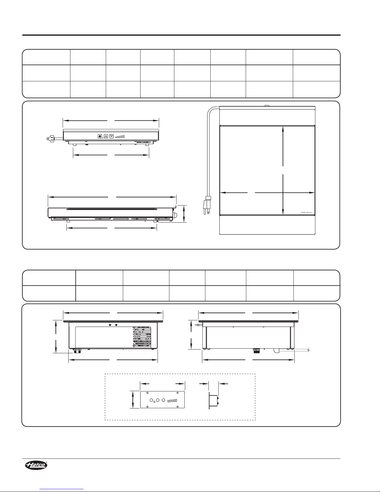
Dimensions — Countertop Models
Model Width (A) Depth (B) Height (C)
IWRM-C1-1317-06
13″
(330 mm)
17-3/4″
(450 mm)
2-1/4″
(57 mm)
Footprint
Width (D)
10-1/4″
(260 mm)
Footprint
Depth (E)
12-1/4″
(310 mm)
Warming Surface
Width (F)
13″
(330 mm)
Warming Surface
Depth (G)
12″
(307 mm)
IWRM-CD1-03
13″
(330 mm)
17-3/4″
(450 mm)
Dimensions — Built-In Models
Cooking Surface
Model
IWRM-B1-1313-06 13″
Width (A)
(330 mm)
Cooking Surface
2-1/4″
(57 mm)
Depth (B) Height (C)
13″
(330 mm)
10-1/4″
(260 mm)
4-1/4″
(108 mm)
12-1/4″
(310 mm)
Unit
Height (D)
3-3/4″
(95 mm)
13″
(330 mm)
Under-Counter
Width (E)
11-5/8″
(294 mm)
12″
(307 mm)
Under-Counter
Depth (F)
12″
(304 mm)
6
Form No. IWRMM-0119

INSTALLATION
WARNING
CAUTION
WARNING
General
Induction Warmers are shipped completely assembled and
ready for use. Built-in units require installation into a countertop
(see procedures in this section). Care should be taken when
unpacking the shipping carton to avoid damage to the unit and
components enclosed.
ELECTRIC SHOCK HAZARD: Unit is not weatherproof.
Locate unit indoors where ambient air temperature is a
minimum of 70°F (21°C) and a maximum of 124°F (51°C).
FIRE HAZARD:
• Make sure to follow the installation information listed
below for specific Induction Warmers. If safe distances are
not maintained, discoloration or combustion could occur.
a. Locate countertop unit a minimum of 1″ (25 mm)
from combustible walls and materials.
b. Locatebuilt-in unit with a minimum of 2″ (51 mm)
between front, sides, and bottom of unit and any
interior surface.
c. Locatebuilt-inunit withaminimum of6″(152mm)
between back of unit and any interior surface.
• Do not obstruct air ventilation openings on sides and
bottom of unit. Unit combustion or malfunction may
occur.
• Do not place unit near or underneath curtains or other
combustible materials. Items near or above unit could
catch fire causing injury and/or damage to unit.
Do not block or restrict air flow to air intake or exhaust
openings on bottom of unit.
Locate unit at proper counter height in an area that is
convenient for use. Location should be level to prevent unit
or its contents from falling accidentally and strong enough
to support weight of unit and contents.
1. Remove the unit from the carton.
2. Remove tape and protective packaging from all surfaces of
the unit.
NOTE: To prevent delay in obtaining warranty coverage,
complete online warranty registration. See
IMPORTANT OWNER INFORMATION for details.
3. If the unit is a countertop model, place the unit in the
desired location. Make sure the location:
• is level and at the proper counter height.
• is strong enough to support the unit and its contents.
• provides a minimum of 1″ (25 mm) clearance from
combustible materials.
• is large enough for all four feet of the unit to be positioned
securely on the countertop.
4. If the unit is a built-in model, refer to the “Installing Built-In
Models” procedure in this section.
NOTE: Avoid areas that may be subject to active air
movements or currents (i.e., near exhaust fans/hoods,
air conditioning ducts, and exterior doors).
Installing Built-In Models
Built-In models require installation into a countertop before
operation. Two types of built-in installation are available, flush
mount and trim ring. Use the following information and the
appropriate procedure to install a built-in unit.
ELECTRIC SHOCK HAZARD: Unit is not weatherproof.
Locate unit indoors where ambient air temperature is a
minimum of 70°F (21°C) and a maximum of 124°F (51°C).
Preparing the Installation Site
The unit is designed to allow easy removal of the electronic
components from the underside of the unit without having to
remove the installed ceramic glass top. IMPORTANT! Make
sure that the installation location allows access to the
underside of the unit for maintenance and cleaning after
it has been placed into the countertop. Other specifications
include:
• Make sure a grounded electrical receptacle of the correct
voltage, size, and plug configuration is within reach of the
unit’s 71″ (1800 mm) power cord inside the cabinet. See the
SPECIFICATIONS section for details.
• Make sure a vertical surface for control panel installation
is available in the cabinet within reach of the 39″
(1000 mm) control cable that connects the control panel to
the Induction Warmer.
• Make sure a minimum clearance of 2″ (51 mm) will be
available between the front, sides, and bottom of the unit
and any interior surface.
• Make sure a minimum clearance of 6″ (152 mm) will be
available between the back of the unit and any interior
surface.
Ventilation Requirements
Proper ventilation of the cabinet below a built-in unit is required
to prevent over-heating the electronics in the unit. Proper
ventilation provides cool, intake air to the front of the unit and
an escape for the hot, exhaust air from the back of the unit.
• For standard installations, a ventilation opening with a
minimum size of 2″ x 10″/20 square inches (5 x 25 cm/
129 square cm) is required behind the air exhaust openings
on the back of the unit, starting no more than 2″ (51 mm) down
from the top of the unit. An additional 2″ x 10″/20 square inch
(5 x 25 cm/129 square cm) ventilation opening is required in
the front of the cabinet to provide cool intake air. Louvered
or grill-style panels should be installed in the openings.
• For installations where the cabinet is against a wall or
no rear ventilation is possible, keep the front controlside of the cabinet open. If the front cannot be left open,
install two ventilation openings in the front panel of the
cabinet, one at the bottom of the cabinet and one near
the control panel at the top of the cabinet. Each opening
must be a minimum size of 2″ x 10″/20 square inches
(5 x 25 cm/129 square cm). DO NOT install a shelf,
partition, or any other equipment inside the cabinet
underneath the unit—the space must remain wide open
for air circulation.
NOTE: Make sure the interior temperature of the cabinet does
not rise above 124°F (51°C) while the Induction Warmer
is operating. If the temperature rises too high, additional
ventilation openings will be required.
Form No. IWRMM-0119
7

INSTALLATION
Outer Cutout
Step
Inner Cutout
Countertop
3/8" (9.5 mm)
13-1/8″
(333 mm)
12-1/4″
(311 mm)
11-13/16″
(300 mm)
Countertop
Inner Cutout
Outer Cutout
13-1/8″
(333 mm)
Back
of
Unit
Front
of
Unit
Silicone
Power Cord
Control Cable Port
Countertop
13-1/2″
(343 mm)
13-1/2″
(343 mm)
Countertop
Flush Mount Installation
Flush mount installation requires a prepared, solid material
countertop and provides a seamless transition between the
countertop and the induction range. A special, “stepped” cutout
is required for flush mount installation.
NOTE: A Flush Mount Kit is available as an accessory that
enables flush mount installation in a straight, nonstepped countertop cutout. Refer to OPTIONS AND
ACCESSORIES for details.
1. Carefully measure and cut the step-style opening in the
countertop. The thickness of the solid material countertop
material should be a minimum of 3/4″ (19 mm).
a. Refer to the Flush Mount Countertop Cutouts illustration
below for the dimensions of each cutout.
• Two cutouts are required;
a partial depth outer
cutout, and an inner
cutout—the material
between the cutouts is
removed. This creates a
step for the flange of the
Induction Warmer to sit
on below the level of the
countertop.
b. Create the outer, partial depth cutout.
• Depth = 3/8″ (9.5 mm)
c. Create the inner cutout. Then, remove the material in
between the cutouts to create the step.
5. Carefully lower the unit into the opening, making sure the
power cord does not get pinched.
Standard Flush Mount Installation
6. Apply a bead of National Sanitation Foundation (NSF)approved silicone sealant in the gap between the
countertop and the Induction Warmer. To apply a clean,
consistent sealant bead:
a. Make sure the unit is centered in the countertop cutout.
b. Install masking tape on each side of the gap to define the
edge of the sealant.
c. Carefully apply sealant into the gap.
d. Quickly smooth the sealant surface.
e. Carefully remove the masking tape before the sealant
dries.
NOTE: The silicone sealant must be rated for use at
temperatures up to 250°F (121°C)
7. Install the control panel in the desired location. Refer to the
“Installing the Control Panel” procedure.
8. Plug the unit into a properly grounded electrical receptacle
of the correct voltage, size, and plug configuration. See the
SPECIFICATIONS section for details.
Trim Ring Installation
Trim ring installation requires the purchase of the accessory
trim ring and can be performed in a solid material or stainless
steel countertop.
TRIM-IWRM1 = Model IWRM-B1-1313-06
Use the following procedure for trim ring installation.
1. Carefully measure and cut the opening in the countertop.
Flush Mount Countertop Cutouts
2. Cut and drill the appropriate holes in the vertical surface
where the control enclosure will be installed. Refer to
the “Installing the Control Panel” procedure for cutout
dimensions.
3. Cut the required openings in the cabinetry to provide proper
ventilation to the induction range. Refer to the “Ventilation
Requirements” listed previously in this section.
4. If necessary, make structural modifications or add bracing
underneath the countertop to ensure the countertop will
support the weight of the unit and its contents.
NOTE: The countertop must be level to ensure proper operation
of the Induction Warmer.
Trim Ring Installation Countertop Cutout
2. Cut and drill the appropriate holes in the vertical surface
where the control enclosure will be installed. Refer
to the “Installing the Control Panel” procedure in the
INSTALLATION section for details.
8
Form No. IWRMM-0119

Silicone
Trim
Ring
Countertop
Cutaway view of trim ring.
Back
of
Unit
Front
of
Unit
WARNING
5-1/8″
(129 mm)
Cabinet Wall
3/8"
(9 mm)
1-13/16"
(46 mm)
3/16"
(4 mm)
4-3/8"
(111 mm)
Silicone Sealant
1-1/2"
(38 mm)
Mounting Screw
Control Cable
Silicone
Sealant
Cabinet Wall
INSTALLATION
3. Cut the required openings in the cabinetry to provide proper
ventilation to the Induction Warmer. Refer to the “Ventilation
Requirements” in this section for details.
4. If necessary, make structural modifications or add bracing
underneath the countertop to ensure the countertop will
support the weight of the unit and its contents.
NOTE: The countertop must be level to ensure proper operation
of the Induction Warmer.
5. Apply a bead of NSF-approved silicone sealant onto the
countertop material around the cutout opening.
NOTE: The silicone sealant must be rated for use at
temperatures up to 250°F (121°C)
6. Install the trim ring into the countertop opening.
7. Carefully lower the unit into the trim ring, making sure the
power cord and control cable do not get pinched.
Standard Trim Ring Installation
8. Apply a bead of NSF-approved silicone sealant in the gap
between the trim ring and the Induction Warmer.
a. Make sure the unit is centered in the trim ring.
b. Install masking tape on each side of the gap to define the
edge of the sealant.
c. Carefully apply sealant into the gap.
d. Quickly smooth the sealant surface.
e. Carefully remove the masking tape before the sealant
dries.
NOTE: The silicone sealant must be rated for use at
temperatures up to 250°F (121°C)
9. Install the control panel in the desired location. Refer to the
“Installing the Control Panel” procedure.
10. Plug the unit into a properly grounded electrical receptacle
of the correct voltage, size, and plug configuration. See the
SPECIFICATIONS section for details.
Installing the Control Panel
Use the following procedure to install the control panel.
Remote mounted control panel must be mounted on a
vertical wall and installed in vertical position. Mounting
control panel in horizontal position may result in collection
of liquids and lead to an electric shock.
1. Carefully measure and cut the opening in the cabinet wall
for the control panel.
2. Drill the appropriate holes around the cutout for the control
panel mounting screws (not supplied).
Control Panel Cutout and Screw Hole Dimensions
3. Apply a 1/4″ (6 mm) bead of NSF-approved silicone sealant
where the trim on the control panel will contact the cabinet
surface. Refer to the “Control Panel Cutout and Screw Hole
Dimensions” illustration for silicone placement.
4. Position the control panel into the cutout opening through
the front of the cabinet. Make sure to embed the trim on the
control panel into the silicone.
5. Fasten the control panel to the vertical surface using four
mounting screws (not supplied).
6. Connect the control cable on the control panel to the control
cable port on the bottom of the induction range.
Form No. IWRMM-0119
Installing the Control Panel
9

OPERATION
WARNING
CAUTION
On/Off Button
Temperature Control
Arrow Buttons
Temperature Setting Indicators
(shown at level 3)
General
Use the following information and procedures to operate both
countertop and built-in Induction Warmers. NOTICE: Do not
move a countertop unit during operation.
Read all safety messages in the IMPORTANT SAFETY
INFORMATION section before operating this equipment.
BURN HAZARD:
• Do not leave metal objects or utensils on or near
induction range. They may become hot.
• Use caution when wearing rings, watches, or other
ferrous objects around induction range. They may
become hot.
• Some exterior surfaces on unit will get hot. Use caution
when touching these areas.
Pan Specifications
Pans used with an Induction Warmer must meet the following
specifications:
• Made of material with magnetic properties (ferrous material)
- Enameled Steel Pans
- Cast Iron Pans
- Stainless Steel Pans
- Aluminum Pans w/ferrous base
• Proper size (measurements given are the pan bottom
diameter)
IWRM-C1-1317-06, IWRM-CD1-03
- Minimum = 4″ (102 mm), Maximum = 13″ (330 mm)
IWRM-CB1-1313-06
- Minimum = 4″ (102 mm), Maximum = 12″ (300 mm)
• Flat bottom
The following pans cannot be used with an Induction Warmer:
• Glass Pans
• Aluminum Pans without a ferrous base
• Earthenware Pans
• Ceramic Pans
• Copper Pans
NOTE: The Induction Warmer automatically detects if a pan
is induction-ready. If a pan is placed on the unit during
operation that is not induction-ready, temperature
setting indicator “1” will flash, and the unit will not
operate. See TROUBLESHOOTING section.
Startup
1. Before turning on the unit each day, clean the glass surface
using an appropriate cleaning wipe, damp paper towel, or
a damp cloth. CAUTION! Wipe up all spills and splashes
immediately. Make sure unit is dry before using. Do not
allow liquid to run into air inlet filter on bottom of unit.
NOTE: The unit can be turned off at any time by pressing the
button.
NOTE: The cooling fan in the unit will not start until the unit gets
hot. Once the fan turns on, it will run until the unit cools.
2. Plug the unit into a properly grounded electrical receptacle
of the correct voltage, size, and plug configuration. See the
SPECIFICATIONS section for details.
3. Place an induction-ready pan on the unit. The Induction
Warmer will not operate without a pan centered inside the
warming zone pattern on the glass surface.
4. Press the button to turn on the unit.
• The temperature setting indicators will illuminate to show
the current temperature setting. The unit will start up at
the same temperature setting from when it was last shut
down.
5. Press the or button to adjust the temperature to the
desired setting.
NOTE: Heat generation will stop automatically and the unit will
enter “standby” mode whenever a pan is removed from
the glass surface. After 10 minutes with no pan present,
the unit will shut down.
Shutdown
1. Press the button to turn off the unit.
Induction Warmer Food Holding Tips
Hatco Induction Warmers maintain holding temperatures very
efficiently and effectively. However, ambient conditions, food
type, and other factors play a critical role in the actual food
temperature. Use the following tips to ensure proper and
consistent holding temperatures.
• Cover food with a lid and stir often, if applicable.
Uncovered food product will lose heat quickly due to
ambient conditions like room temperature and active air
movement.
• Check food temperature regularly and make adjustments
to the temperature setting accordingly.
• Hold foods that are appropriate for the Induction Warmer.
A thick liquid product, like chili, that is held in a pan with
a lid and stirred frequently will hold temperature for
longer and much more consistently than uncovered fried
chicken pieces.
Induction Warmer Control Panel
10
Form No. IWRMM-0119
 Loading...