

Hatco IWRM, IWRM-C1-1317-06, IWRM-CD1-03, IWRM-B1-1313-06 Installation And Operating Manual
Page 1

hatcocorp.com
WARNING
ADVERTENCIA
Register Online!
(see page 2)
S’inscrire en ligne !
(voir page 15)
Induction Warmer
Réchaud à induction
IWRM Series/Série
Installation and Operating Manual
Manuel d’installation et d’utilisation
Do not operate this equipment unless you
have read and understood the contents
of this manual! Failure to follow the
instructions contained in this manual
may result in serious injury or death.
This manual contains important safety
information concerning the maintenance,
use, and operation of this product. If
you’re unable to understand the contents
of this manual, please bring it to the
attention of your supervisor. Keep this
manual in a safe location for future
reference.
English = p 2
P/N 07.04.897.00 © 2019 Hatco Corporation
No opere este equipo al menos que haya
leído y comprendido el contenido de este
manual! Cualquier falla en el seguimiento
de las instrucciones contenidas en
este manual puede resultar en un serio
lesión o muerte. Este manual contiene
importante información sobre seguridad
concerniente al mantenimiento, uso y
operación de este producto. Si usted
no puede entender el contenido de
este manual por favor pregunte a su
supervisor. Almacenar este manual en
una localización segura para la referencia
futura.
AVERTISSEMENT
Ne pas utiliser cet équipement sans avoir
lu et compris le contenu de ce manuel ! Le
non-respect des instructions contenues
dans ce manuel peut entraîner de
graves blessures ou la mort. Ce manuel
contient des informations importantes
concernant l’entretien, l’utilisation et le
fonctionnement de ce produit. Si vous ne
comprenez pas le contenu de ce manuel,
veuillez le signaler à votre supérieur.
Conservez ce manuel dans un endroit
sûr pour pouvoir vous y référer plus tard.
Français = p 15
Page 2
CONTENTS
WARNING
CAUTION
Important Owner Information .............................................. 2
Introduction ...........................................................................2
Important Safety Information .............................................. 3
Model Description ................................................................4
Model Designation ...............................................................5
Specifications ....................................................................... 5
Plug Configurations ............................................................. 5
Electrical Rating Chart ......................................................... 5
Dimensions ......................................................................... 6
Installation .............................................................................7
General ................................................................................ 7
Installing Built-In Models .....................................................7
Installing the Control Panel .................................................9
IMPORTANT OWNER INFORMATION
Record the model number, serial number, voltage, and
purchase date of the unit in the spaces below (specification
label located on the underside of the unit). Please have this
information available when calling Hatco for service assistance.
Model No. ________________________________________
Serial No. _________________________________________
Voltage ___________________________________________
Date of Purchase ___________________________________
Register your unit!
Completing online warranty registration will prevent delay in
obtaining warranty coverage. Access the Hatco website at
www.hatcocorp.com, select the Support pull-down menu,
and click on “Warranty”.
Operation .............................................................................10
General .............................................................................. 10
Induction Warmer Food Holding Tips ................................ 10
Maintenance ........................................................................ 11
General .............................................................................. 11
Daily Cleaning ................................................................... 11
Troubleshooting Guide ......................................................12
Options and Accessories .................................................. 12
Limited Warranty ................................................................14
Service Information ............................................................ 14
Authorized Parts Distributors ........................... Back Cover
Business
Hours: 7:00 am to 5:00 pm Monday–Friday,
Central Time (CT)
(Summer Hours — June to September:
7:00 am to 5:00 pm Monday–Thursday
7:00 am to 4:00 pm Friday)
Telephone: 800-558-0607; 414-671-6350
E-mail: support@hatcocorp.com
24 Hour 7 Day Parts and Service
Assistance available in the United States
and Canada by calling 800-558-0607.
Additional information can be found by visiting our web site at
www.hatcocorp.com.
INTRODUCTION
Hatco Induction Warmers offer a safe, efficient, and
attractive way to hold foods in commercial kitchens as well
as display locations (food lines, buffets, etc...). The high
efficiency and accuracy of induction technology make Hatco
Induction Warmers the perfect choice for quality foodservice
organizations.
Induction technology relies on the creation of a magnetic field
between the induction coils below the glass surface of the
unit and an “induction-ready” pan sitting on top of the glass
surface. This magnetic field generates induction currents in
the base of the pan, which heat the pan instantly. That heat
then is transferred to the pan contents. Since the magnetic field
exists only between the induction coils and a magnetic material
(ferrous material), the glass surface between the two does not
become heated, eliminating heat loss and increasing efficiency.
When the magnetic field is “broken” by turning off the unit or
removing the pan, heat generation stops instantly.
Hatco Induction Warmers are products of extensive research
and field testing. The materials used were selected for
maximum durability, attractive appearance, and optimum
performance. Every unit is inspected and tested thoroughly
prior to shipment.
This manual provides the installation, safety, and operating
instructions for Hatco Induction Warmers. Hatco recommends
all installation, operating, and safety instructions appearing in
this manual be read prior to installation or operation of a unit.
Safety information that appears in this manual is identified by
the following signal word panels:
WARNING indicates a hazardous situation which, if not
avoided, could result in death or serious injury.
CAUTION indicates a hazardous situation which, if not
avoided, could result in minor or moderate injury.
NOTICE
NOTICE is used to address practices not related to personal
injury.
2
Form No. IWRMM-0119
Page 3

IMPORTANT SAFETY INFORMATION
Read the following important safety information before using this equipment to avoid serious
injury or death and to avoid damage to equipment or property.
WARNING
ELECTRIC SHOCK HAZARD:
• Plug unit into a properly grounded electrical receptacle
of the correct voltage, size, and plug configuration. If
plug and receptacle do not match, contact a qualified
electrician to determine and install proper voltage and
size electrical receptacle.
• Turn OFF power, unplug power cord, and allow unit to
cool before performing any cleaning, adjustments, or
maintenance.
• Remote mounted control panel must be mounted on a
vertical wall and installed in vertical position. Mounting
control panel in horizontal position may result in
collection of liquids and lead to an electric shock.
• DO NOT submerge or saturate with water. Do not allow
liquids to spill into unit. Unit is not waterproof. Do not
operate if unit has been submerged or saturated with
water.
• Unit is not weatherproof. Locate unit indoors where
ambient air temperature is a minimum of 70°F (21°C)
and a maximum of 124°F (51°C).
• Do not steam clean or use excessive water on the unit.
• This unit is not “jet-proof” construction. Do not use
jet-clean spray to clean this unit.
• Do not clean unit when it is energized or hot.
• Do not pull unit by power cord.
• Discontinue use if power cord is frayed or worn.
• Do not attempt to repair or replace a damaged power
cord. Cord must be replaced by an Authorized Hatco
Service Agent or a person with similar qualifications.
• This unit must be serviced by qualified personnel only.
Service by unqualified personnel may lead to electric
shock or burn.
• Use only Genuine Hatco Replacement Parts when
service is required. Failure to use Genuine Hatco
Replacement Parts will void all warranties and may
subject operators of the equipment to hazardous
electrical voltage, resulting in electrical shock or burn.
Genuine Hatco Replacement Parts are specified to
operate safely in the environments in which they are
used. Some after-market or generic replacement parts
do not have the characteristics that will allow them to
operate safely in Hatco equipment.
EXPLOSION HAZARD: Do not heat unopened containers
of food on unit. Sealed, heated containers may burst open.
ELECTROMAGNETIC INTERFERENCE HAZARD: This
unit generates close-range electromagnetic fields. It has
been designed to meet the applicable standards for noninterference with other electronic devices. Make sure other
electronic devices in the vicinity, including pacemakers
and other active implants, have been designed to meet
their corresponding applicable standards. As a precaution,
donot operate unitorcomewithin 12ʺ(305mm)of unit
with a pacemaker or other active implant.
WARNING
FIRE HAZARD:
• Make sure to follow the installation information listed
below for specific Induction Warmers. If safe distances
are not maintained, discoloration or combustion could
occur.
a. Locate countertop unit a minimum of 1″ (25 mm)
from combustible walls and materials.
b. Locatebuilt-inunitwithaminimum of 2″ (51mm)
between front, sides, and bottom of unit and any
interior surface.
c. Locatebuilt-in unitwithaminimumof6″(152mm)
between back of unit and any interior surface.
• Do not obstruct air ventilation openings on sides and
bottom of unit. Unit combustion or malfunction may occur.
• Do not place unit near or underneath curtains or other
combustible materials. Items near or above unit could
catch fire causing injury and/or damage to unit.
This unit is not intended for use by children or persons with
reduced physical, sensory, or mental capabilities. Ensure
proper supervision of children and keep them away from unit.
Make sure all operators have been instructed on the safe
and proper use of the unit.
This unit has no “user-serviceable” parts. If service
is required on this unit, contact an Authorized Hatco
Service Agent or contact the Hatco Service Department at
800-558-0607 or 414-671-6350.
CAUTION
RISK OF FIRE AND ELECTRIC SHOCK: Replace detachable
power cord and jumper power cord with Hatco Replacement
Parts only (02.18.990.00 and 02.18.991.00). Unit receptacles
intended for use only with other Hatco IWRMCD family
members. Maximum load shall not exceed 1080 watts.
BURN HAZARD:
• Do not leave metal objects or utensils on or near
induction range. They may become hot.
• Use caution when wearing rings, watches, or other
ferrous objects around induction range. They may
become hot.
• Some exterior surfaces on unit will get hot. Use caution
when touching these areas.
Do not block or restrict air flow to air intake or exhaust
openings on bottom of unit.
Do not store anything on top of unit.
Locate unit at proper counter height in an area that is
convenient for use. Location should be level to prevent
unit or its contents from falling accidentally and strong
enough to support weight of unit and contents.
NOTICE
Never use aluminum foil on Induction Warmer. Aluminum
foil will melt and damage unit.
Form No. IWRMM-0119
3
Page 4

IMPORTANT SAFETY INFORMATION
Ceramic
Glass
Surface
On/Off
Button
Temperature Control Arrow Buttons
Temperature Setting Indicators
Ceramic
Glass
Surface
Detachable
Power Cord
On/Off
Button
Temperature Control Arrow Buttons
Jumper
Power Cord
Temperature Setting Indicators
Ceramic Glass
Surface
Power Cord
Remote
Control
Panel
Control
Cable
NOTICE
Do not place objects with magnetic properties (credit cards,
cassette tapes, etc...) on or near unit during operation.
Use only wipes, pads, and cleaners designed specifically
for cleaning ceramic glass surfaces.
Use non-abrasive cleaners and cloths only. Abrasive
cleaners and cloths could scratch finish of unit, marring its
appearance and making it susceptible to soil accumulation.
MODEL DESCRIPTION
All Models
Hatco Induction Warmers are equipped with a single
induction coil underneath a ceramic glass surface. Each
model features a control panel with a On/Off Button,
Temperature Control Arrow Buttons, and Temperature Setting
Indicators. All Induction Warmers include either an attached
71″ (1800 mm) power cord with plug or a detachable 71″
(1800 mm) power cord with plug.
NOTE: Refer to “Pan Specifications” in the OPERATION section
of this manual for details on “induction-ready” pans,
pans not suitable for induction warming, and pan sizes.
Hatco Induction Warmers have several safeguards built into
each unit that ensure protection to the unit as well as the
operators.
• A fan-driven ventilation system ensures that the electronic
circuits in the unit do no overheat. Temperature probes
monitor the electronic circuits and will signal the unit to
shut down if the circuits get too hot.
• A temperature probe in the warming zone monitors the
zone temperature. This probe detects overheating in the
warming zone due to an empty pan.
• Electronic circuitry in the warming zone detects when a
small, ferrous object (such as a fork, spoon, or ring) is
placed on the unit, and the unit will not operate.
NOTICE
Do not locate unit in area with excessive air movement
around unit. Avoid areas that may be subject to active air
movements or currents (i.e., near exhaust fans/hoods, air
conditioning ducts, and exterior doors).
This unit is intended for commercial use only—NOT for
household use.
Model IWRM-CD1-03
Model IWRM-CD1-03 Induction Warmers are low wattage,
daisy chain units with a detachable power cord with plug. Using
the included 17″ (432 mm) jumper power cord, up to five of
these models can be connected together off of one electrical
receptacle (see OPTIONS AND ACCESSORIES for additional
jumper power cords).
NOTE: For Canadian units, a total of four units can be
connected together off of one electrical receptacle.
Countertop Models
Countertop Induction Warmers are portable, countertop
Induction Warmers. They are available as standalone units or
as “daisy-chain” units.
Model IWRM-C1-1317-06
Model IWRM-C1-1317-06 Induction Warmers are standalone
units with an attached power cord and plug.
Model IWRM-C1-1317-06
Model IWRM-CD1-03
Built-In Models
Built-In Induction Warmers are designed to be installed into a
variety of solid material countertops. The unit includes a remote
control panel that connects to the Induction Warmer with a
detachable 39″ (1000 mm) control cable.
Model IWRM-B1-1313-06
4
Form No. IWRMM-0119
Page 5

I W R M - x 1 - x x x x - x x
Induction
Unit Wattage
06 = 600 W
03 = 360 W (Daisy Chain model)
Single Coil
Glass Surface Depth
Glass Surface Width
Warmer
C = Countertop
CD = Countertop Daisy Chain
B = Built-In
Plug Configurations
WARNING
NEMA 5-15P
Units are supplied from the factory with either an attached
power cord and plug or a detachable power cord and plug,
depending on the unit. Plugs are supplied according to the
application.
MODEL DESIGNATION
SPECIFICATIONS
ELECTRIC SHOCK HAZARD: Plug unit into a properly
grounded electrical receptacle of the correct voltage,
size, and plug configuration. If plug and receptacle do not
match, contact a qualified electrician to determine and
install proper voltage and size electrical receptacle.
NOTE: The specification label is located on the bottom of the
unit. See label for serial number and verification of unit
electrical information.
NOTE: Receptacle not supplied by Hatco. All units must be
connected to a dedicated circuit.
Plug Configurations
Electrical Rating Chart — Countertop Models
Model Voltage Watts Amps Plug Configuration Shipping Weight
IWRM-C1-1317-06 120 600 5.0 NEMA 5-15P 12 lbs. (6 kg)
IWRM-CD1-03 120 360 3.0 NEMA 5-15P 12 lbs. (6 kg)
Electrical Rating Chart — Built-In Models
Model Voltage Watts Amps Plug Configuration Shipping Weight
IWRM-B1-1313-06 120 600 5.0 NEMA 5-15P 12 lbs. (6 kg)
Form No. IWRMM-0119
5
Page 6
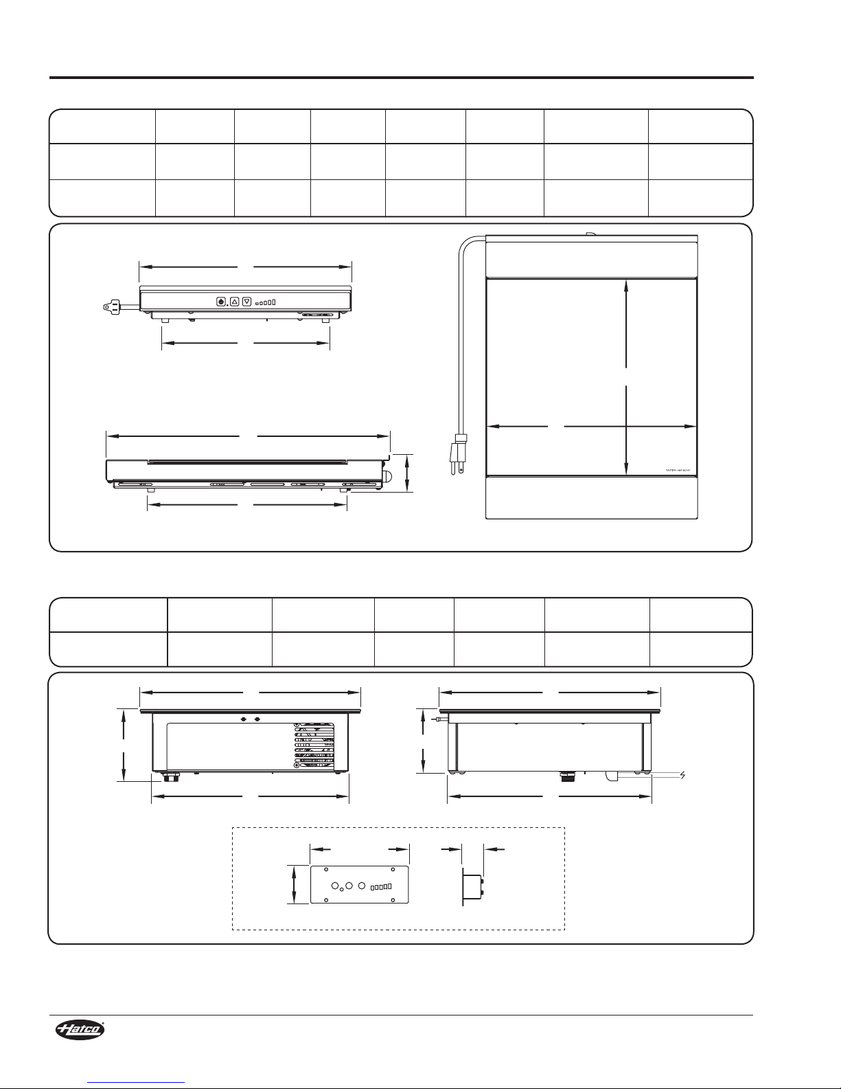
SPECIFICATIONS
A
C
G
F
B
E
D
Front View
Side View
Top View
A B
C
5-3/8"
(137 mm)
1-1/4"
(32 mm)
2-1/4"
(56 mm)
D
E F
Front View
Remote Control Panel
SideView
Dimensions — Countertop Models
Model Width (A) Depth (B) Height (C)
IWRM-C1-1317-06
13″
(330 mm)
17-3/4″
(450 mm)
2-1/4″
(57 mm)
Footprint
Width (D)
10-1/4″
(260 mm)
Footprint
Depth (E)
12-1/4″
(310 mm)
Warming Surface
Width (F)
13″
(330 mm)
Warming Surface
Depth (G)
12″
(307 mm)
IWRM-CD1-03
13″
(330 mm)
17-3/4″
(450 mm)
Dimensions — Built-In Models
Cooking Surface
Model
IWRM-B1-1313-06 13″
Width (A)
(330 mm)
Cooking Surface
2-1/4″
(57 mm)
Depth (B) Height (C)
13″
(330 mm)
10-1/4″
(260 mm)
4-1/4″
(108 mm)
12-1/4″
(310 mm)
Unit
Height (D)
3-3/4″
(95 mm)
13″
(330 mm)
Under-Counter
Width (E)
11-5/8″
(294 mm)
12″
(307 mm)
Under-Counter
Depth (F)
12″
(304 mm)
6
Form No. IWRMM-0119
Page 7

INSTALLATION
WARNING
CAUTION
WARNING
General
Induction Warmers are shipped completely assembled and
ready for use. Built-in units require installation into a countertop
(see procedures in this section). Care should be taken when
unpacking the shipping carton to avoid damage to the unit and
components enclosed.
ELECTRIC SHOCK HAZARD: Unit is not weatherproof.
Locate unit indoors where ambient air temperature is a
minimum of 70°F (21°C) and a maximum of 124°F (51°C).
FIRE HAZARD:
• Make sure to follow the installation information listed
below for specific Induction Warmers. If safe distances are
not maintained, discoloration or combustion could occur.
a. Locate countertop unit a minimum of 1″ (25 mm)
from combustible walls and materials.
b. Locatebuilt-in unit with a minimum of 2″ (51 mm)
between front, sides, and bottom of unit and any
interior surface.
c. Locatebuilt-inunit withaminimum of6″(152mm)
between back of unit and any interior surface.
• Do not obstruct air ventilation openings on sides and
bottom of unit. Unit combustion or malfunction may
occur.
• Do not place unit near or underneath curtains or other
combustible materials. Items near or above unit could
catch fire causing injury and/or damage to unit.
Do not block or restrict air flow to air intake or exhaust
openings on bottom of unit.
Locate unit at proper counter height in an area that is
convenient for use. Location should be level to prevent unit
or its contents from falling accidentally and strong enough
to support weight of unit and contents.
1. Remove the unit from the carton.
2. Remove tape and protective packaging from all surfaces of
the unit.
NOTE: To prevent delay in obtaining warranty coverage,
complete online warranty registration. See
IMPORTANT OWNER INFORMATION for details.
3. If the unit is a countertop model, place the unit in the
desired location. Make sure the location:
• is level and at the proper counter height.
• is strong enough to support the unit and its contents.
• provides a minimum of 1″ (25 mm) clearance from
combustible materials.
• is large enough for all four feet of the unit to be positioned
securely on the countertop.
4. If the unit is a built-in model, refer to the “Installing Built-In
Models” procedure in this section.
NOTE: Avoid areas that may be subject to active air
movements or currents (i.e., near exhaust fans/hoods,
air conditioning ducts, and exterior doors).
Installing Built-In Models
Built-In models require installation into a countertop before
operation. Two types of built-in installation are available, flush
mount and trim ring. Use the following information and the
appropriate procedure to install a built-in unit.
ELECTRIC SHOCK HAZARD: Unit is not weatherproof.
Locate unit indoors where ambient air temperature is a
minimum of 70°F (21°C) and a maximum of 124°F (51°C).
Preparing the Installation Site
The unit is designed to allow easy removal of the electronic
components from the underside of the unit without having to
remove the installed ceramic glass top. IMPORTANT! Make
sure that the installation location allows access to the
underside of the unit for maintenance and cleaning after
it has been placed into the countertop. Other specifications
include:
• Make sure a grounded electrical receptacle of the correct
voltage, size, and plug configuration is within reach of the
unit’s 71″ (1800 mm) power cord inside the cabinet. See the
SPECIFICATIONS section for details.
• Make sure a vertical surface for control panel installation
is available in the cabinet within reach of the 39″
(1000 mm) control cable that connects the control panel to
the Induction Warmer.
• Make sure a minimum clearance of 2″ (51 mm) will be
available between the front, sides, and bottom of the unit
and any interior surface.
• Make sure a minimum clearance of 6″ (152 mm) will be
available between the back of the unit and any interior
surface.
Ventilation Requirements
Proper ventilation of the cabinet below a built-in unit is required
to prevent over-heating the electronics in the unit. Proper
ventilation provides cool, intake air to the front of the unit and
an escape for the hot, exhaust air from the back of the unit.
• For standard installations, a ventilation opening with a
minimum size of 2″ x 10″/20 square inches (5 x 25 cm/
129 square cm) is required behind the air exhaust openings
on the back of the unit, starting no more than 2″ (51 mm) down
from the top of the unit. An additional 2″ x 10″/20 square inch
(5 x 25 cm/129 square cm) ventilation opening is required in
the front of the cabinet to provide cool intake air. Louvered
or grill-style panels should be installed in the openings.
• For installations where the cabinet is against a wall or
no rear ventilation is possible, keep the front controlside of the cabinet open. If the front cannot be left open,
install two ventilation openings in the front panel of the
cabinet, one at the bottom of the cabinet and one near
the control panel at the top of the cabinet. Each opening
must be a minimum size of 2″ x 10″/20 square inches
(5 x 25 cm/129 square cm). DO NOT install a shelf,
partition, or any other equipment inside the cabinet
underneath the unit—the space must remain wide open
for air circulation.
NOTE: Make sure the interior temperature of the cabinet does
not rise above 124°F (51°C) while the Induction Warmer
is operating. If the temperature rises too high, additional
ventilation openings will be required.
Form No. IWRMM-0119
7
Page 8

INSTALLATION
Outer Cutout
Step
Inner Cutout
Countertop
3/8" (9.5 mm)
13-1/8″
(333 mm)
12-1/4″
(311 mm)
11-13/16″
(300 mm)
Countertop
Inner Cutout
Outer Cutout
13-1/8″
(333 mm)
Back
of
Unit
Front
of
Unit
Silicone
Power Cord
Control Cable Port
Countertop
13-1/2″
(343 mm)
13-1/2″
(343 mm)
Countertop
Flush Mount Installation
Flush mount installation requires a prepared, solid material
countertop and provides a seamless transition between the
countertop and the induction range. A special, “stepped” cutout
is required for flush mount installation.
NOTE: A Flush Mount Kit is available as an accessory that
enables flush mount installation in a straight, nonstepped countertop cutout. Refer to OPTIONS AND
ACCESSORIES for details.
1. Carefully measure and cut the step-style opening in the
countertop. The thickness of the solid material countertop
material should be a minimum of 3/4″ (19 mm).
a. Refer to the Flush Mount Countertop Cutouts illustration
below for the dimensions of each cutout.
• Two cutouts are required;
a partial depth outer
cutout, and an inner
cutout—the material
between the cutouts is
removed. This creates a
step for the flange of the
Induction Warmer to sit
on below the level of the
countertop.
b. Create the outer, partial depth cutout.
• Depth = 3/8″ (9.5 mm)
c. Create the inner cutout. Then, remove the material in
between the cutouts to create the step.
5. Carefully lower the unit into the opening, making sure the
power cord does not get pinched.
Standard Flush Mount Installation
6. Apply a bead of National Sanitation Foundation (NSF)approved silicone sealant in the gap between the
countertop and the Induction Warmer. To apply a clean,
consistent sealant bead:
a. Make sure the unit is centered in the countertop cutout.
b. Install masking tape on each side of the gap to define the
edge of the sealant.
c. Carefully apply sealant into the gap.
d. Quickly smooth the sealant surface.
e. Carefully remove the masking tape before the sealant
dries.
NOTE: The silicone sealant must be rated for use at
temperatures up to 250°F (121°C)
7. Install the control panel in the desired location. Refer to the
“Installing the Control Panel” procedure.
8. Plug the unit into a properly grounded electrical receptacle
of the correct voltage, size, and plug configuration. See the
SPECIFICATIONS section for details.
Trim Ring Installation
Trim ring installation requires the purchase of the accessory
trim ring and can be performed in a solid material or stainless
steel countertop.
TRIM-IWRM1 = Model IWRM-B1-1313-06
Use the following procedure for trim ring installation.
1. Carefully measure and cut the opening in the countertop.
Flush Mount Countertop Cutouts
2. Cut and drill the appropriate holes in the vertical surface
where the control enclosure will be installed. Refer to
the “Installing the Control Panel” procedure for cutout
dimensions.
3. Cut the required openings in the cabinetry to provide proper
ventilation to the induction range. Refer to the “Ventilation
Requirements” listed previously in this section.
4. If necessary, make structural modifications or add bracing
underneath the countertop to ensure the countertop will
support the weight of the unit and its contents.
NOTE: The countertop must be level to ensure proper operation
of the Induction Warmer.
Trim Ring Installation Countertop Cutout
2. Cut and drill the appropriate holes in the vertical surface
where the control enclosure will be installed. Refer
to the “Installing the Control Panel” procedure in the
INSTALLATION section for details.
8
Form No. IWRMM-0119
Page 9

Silicone
Trim
Ring
Countertop
Cutaway view of trim ring.
Back
of
Unit
Front
of
Unit
WARNING
5-1/8″
(129 mm)
Cabinet Wall
3/8"
(9 mm)
1-13/16"
(46 mm)
3/16"
(4 mm)
4-3/8"
(111 mm)
Silicone Sealant
1-1/2"
(38 mm)
Mounting Screw
Control Cable
Silicone
Sealant
Cabinet Wall
INSTALLATION
3. Cut the required openings in the cabinetry to provide proper
ventilation to the Induction Warmer. Refer to the “Ventilation
Requirements” in this section for details.
4. If necessary, make structural modifications or add bracing
underneath the countertop to ensure the countertop will
support the weight of the unit and its contents.
NOTE: The countertop must be level to ensure proper operation
of the Induction Warmer.
5. Apply a bead of NSF-approved silicone sealant onto the
countertop material around the cutout opening.
NOTE: The silicone sealant must be rated for use at
temperatures up to 250°F (121°C)
6. Install the trim ring into the countertop opening.
7. Carefully lower the unit into the trim ring, making sure the
power cord and control cable do not get pinched.
Standard Trim Ring Installation
8. Apply a bead of NSF-approved silicone sealant in the gap
between the trim ring and the Induction Warmer.
a. Make sure the unit is centered in the trim ring.
b. Install masking tape on each side of the gap to define the
edge of the sealant.
c. Carefully apply sealant into the gap.
d. Quickly smooth the sealant surface.
e. Carefully remove the masking tape before the sealant
dries.
NOTE: The silicone sealant must be rated for use at
temperatures up to 250°F (121°C)
9. Install the control panel in the desired location. Refer to the
“Installing the Control Panel” procedure.
10. Plug the unit into a properly grounded electrical receptacle
of the correct voltage, size, and plug configuration. See the
SPECIFICATIONS section for details.
Installing the Control Panel
Use the following procedure to install the control panel.
Remote mounted control panel must be mounted on a
vertical wall and installed in vertical position. Mounting
control panel in horizontal position may result in collection
of liquids and lead to an electric shock.
1. Carefully measure and cut the opening in the cabinet wall
for the control panel.
2. Drill the appropriate holes around the cutout for the control
panel mounting screws (not supplied).
Control Panel Cutout and Screw Hole Dimensions
3. Apply a 1/4″ (6 mm) bead of NSF-approved silicone sealant
where the trim on the control panel will contact the cabinet
surface. Refer to the “Control Panel Cutout and Screw Hole
Dimensions” illustration for silicone placement.
4. Position the control panel into the cutout opening through
the front of the cabinet. Make sure to embed the trim on the
control panel into the silicone.
5. Fasten the control panel to the vertical surface using four
mounting screws (not supplied).
6. Connect the control cable on the control panel to the control
cable port on the bottom of the induction range.
Form No. IWRMM-0119
Installing the Control Panel
9
Page 10

OPERATION
WARNING
CAUTION
On/Off Button
Temperature Control
Arrow Buttons
Temperature Setting Indicators
(shown at level 3)
General
Use the following information and procedures to operate both
countertop and built-in Induction Warmers. NOTICE: Do not
move a countertop unit during operation.
Read all safety messages in the IMPORTANT SAFETY
INFORMATION section before operating this equipment.
BURN HAZARD:
• Do not leave metal objects or utensils on or near
induction range. They may become hot.
• Use caution when wearing rings, watches, or other
ferrous objects around induction range. They may
become hot.
• Some exterior surfaces on unit will get hot. Use caution
when touching these areas.
Pan Specifications
Pans used with an Induction Warmer must meet the following
specifications:
• Made of material with magnetic properties (ferrous material)
- Enameled Steel Pans
- Cast Iron Pans
- Stainless Steel Pans
- Aluminum Pans w/ferrous base
• Proper size (measurements given are the pan bottom
diameter)
IWRM-C1-1317-06, IWRM-CD1-03
- Minimum = 4″ (102 mm), Maximum = 13″ (330 mm)
IWRM-CB1-1313-06
- Minimum = 4″ (102 mm), Maximum = 12″ (300 mm)
• Flat bottom
The following pans cannot be used with an Induction Warmer:
• Glass Pans
• Aluminum Pans without a ferrous base
• Earthenware Pans
• Ceramic Pans
• Copper Pans
NOTE: The Induction Warmer automatically detects if a pan
is induction-ready. If a pan is placed on the unit during
operation that is not induction-ready, temperature
setting indicator “1” will flash, and the unit will not
operate. See TROUBLESHOOTING section.
Startup
1. Before turning on the unit each day, clean the glass surface
using an appropriate cleaning wipe, damp paper towel, or
a damp cloth. CAUTION! Wipe up all spills and splashes
immediately. Make sure unit is dry before using. Do not
allow liquid to run into air inlet filter on bottom of unit.
NOTE: The unit can be turned off at any time by pressing the
button.
NOTE: The cooling fan in the unit will not start until the unit gets
hot. Once the fan turns on, it will run until the unit cools.
2. Plug the unit into a properly grounded electrical receptacle
of the correct voltage, size, and plug configuration. See the
SPECIFICATIONS section for details.
3. Place an induction-ready pan on the unit. The Induction
Warmer will not operate without a pan centered inside the
warming zone pattern on the glass surface.
4. Press the button to turn on the unit.
• The temperature setting indicators will illuminate to show
the current temperature setting. The unit will start up at
the same temperature setting from when it was last shut
down.
5. Press the or button to adjust the temperature to the
desired setting.
NOTE: Heat generation will stop automatically and the unit will
enter “standby” mode whenever a pan is removed from
the glass surface. After 10 minutes with no pan present,
the unit will shut down.
Shutdown
1. Press the button to turn off the unit.
Induction Warmer Food Holding Tips
Hatco Induction Warmers maintain holding temperatures very
efficiently and effectively. However, ambient conditions, food
type, and other factors play a critical role in the actual food
temperature. Use the following tips to ensure proper and
consistent holding temperatures.
• Cover food with a lid and stir often, if applicable.
Uncovered food product will lose heat quickly due to
ambient conditions like room temperature and active air
movement.
• Check food temperature regularly and make adjustments
to the temperature setting accordingly.
• Hold foods that are appropriate for the Induction Warmer.
A thick liquid product, like chili, that is held in a pan with
a lid and stirred frequently will hold temperature for
longer and much more consistently than uncovered fried
chicken pieces.
Induction Warmer Control Panel
10
Form No. IWRMM-0119
Page 11

MAINTENANCE
WARNING
WARNING
CAUTION
General
Hatco Induction Warmers are designed for maximum
durability and performance with minimum maintenance.
ELECTRIC SHOCK HAZARD:
• Turn OFF power, unplug power cord, and allow unit to
cool before performing any cleaning, adjustments, or
maintenance.
• DO NOT submerge or saturate with water. Do not allow
liquids to spill into unit. Unit is not waterproof. Do not
operate if unit has been submerged or saturated with
water.
• Do not steam clean or use excessive water on the unit.
• This unit is not “jet-proof” construction. Do not use jetclean spray to clean this unit.
• Do not clean unit when it is energized or hot.
• Discontinue use if power cord is frayed or worn.
• Do not attempt to repair or replace a damaged power
cord. Cord must be replaced by an Authorized Hatco
Service Agent or a person with similar qualifications.
• This unit must be serviced by qualified personnel only.
Service by unqualified personnel may lead to electric
shock or burn.
Daily Cleaning
To maintain performance and preserve the finish of the Induction
Warmer, clean the unit daily. Make sure to use only wipes, pads,
and cleaners designed specifically for cleaning ceramic glass
surfaces.
1. Turn off and unplug the unit. Allow the unit to cool.
2. Remove and wash all food pans.
3. Clean the glass surface using an appropriate cleaning
wipe, damp paper towel, or damp cloth.
• For tough stains and metal marks, use a drop of ceramic
glass cleaner and paper towel.
• For water and scale marks, use a few drops of white
vinegar and paper towel.
NOTICE
Use non-abrasive cleaners and cloths only. Abrasive
cleaners and cloths could scratch finish of unit, marring its
appearance and making it susceptible to soil accumulation.
5. Clean the metal surfaces using a clean, soft cloth and mild
detergent.
6. Wipe dry all metal surfaces using a dry, clean, soft cloth.
ELECTRIC SHOCK HAZARD: Use only Genuine Hatco
Replacement Parts when service is required. Failure to use
Genuine Hatco Replacement Parts will void all warranties
and may subject operators of the equipment to hazardous
electrical voltage, resulting in electrical shock or burn.
Genuine Hatco Replacement Parts are specified to operate
safely in the environments in which they are used. Some
after-market or generic replacement parts do not have the
characteristics that will allow them to operate safely in
Hatco equipment.
This unit has no “user-serviceable” parts. If service
is required on this unit, contact an Authorized Hatco
Service Agent or contact the Hatco Service Department at
800-558-0607 or 414-671-6350.
Use only wipes, pads, and cleaners designed specifically
for cleaning ceramic glass surfaces.
Wipe up all spills and splashes immediately. Make sure unit
is dry before using. Do not allow liquid to run into air inlet
filter on bottom of unit.
Form No. IWRMM-0119
11
Page 12

Make sure power cord is plugged into an appropriate receptacle
(see SPECIFICATIONS section). Check circuit breaker and reset
as necessary. Check for damage to power cord. Check electrical
Temperature setting indicator 1 is
Pan being used is not induction-ready.
Use an induction-ready pan (see “Pan Specifications” in the
TROUBLESHOOTING GUIDE
WARNING
WARNING
12345
12345
12345
12345
12345
12345
Female Plug
Male Plug
This unit must be serviced by qualified personnel only.
Service by unqualified personnel may lead to electric
shock or burn.
ELECTRIC SHOCK HAZARD: Turn OFF power, unplug
power cord, and allow unit to cool before performing any
cleaning, adjustments, or maintenance.
Symptom Probable Cause Corrective Action
Unit does not turn on. No power to unit.
receptacle.
Electronic controls defective. Contact Authorized Service Agent or Hatco for assistance.
flashing and the unit will not heat.
OPERATION section of this manual).
Error Indicator Guide
Problems with the Induction Warmer are indicated by the flashing of one or more of the temperature setting indicators. Below is an
explanation of each error indication. Always investigate and correct the causes of an error.
Error Indication Error Description Corrective Action
Bad Pan Detection Pan being used is not induction-ready.
Unit over voltage
Unit under voltage
Voltage of electrical system is too high for
the unit.
Voltage of electrical system is too low for the
unit.
Place an induction-ready pan on the warmer (see
“Pan Specifications” in the OPERATION section
of this manual).
Plug the unit into a properly grounded electrical
receptacle of the correct voltage, size, and plug
configuration. See the SPECIFICATIONS section
for details
Hardware Error
Fan Error
Communication Error
Unit is experiencing a hardware error and has
shut down to protect unit from damage.
Cooling fan is not working properly. Unit has
shut down for protection against damage.
Internal communication error between
components. Unit has shut down for protection
against damage.
Contact Authorized Service Agent or Hatco for
assistance.
Troubleshooting Questions?
If you continue to have problems resolving an issue, please contact the nearest Authorized Hatco Service Agency or Hatco for
assistance. To locate the nearest Service Agency, log onto the Hatco website at www.hatcocorp.com, select the Support pulldown menu, and click on “Find A Service Agent”; or contact the Hatco Parts and Service Team at:
Telephone: 800-558-0607 or 414-671-6350
e-mail: support@hatcocorp.com
OPTIONS AND ACCESSORIES
Jumper Power Cord
A 17″ (432 mm) jumper power cord is available as an accessory
that provides a power connection from one Induction Warmer
to another. A total of five units can be connected together off
of one electrical receptacle. The male plug on the jumper cord
connects to the power outlet on the upstream unit, and the
female plug connects to the power inlet on the downstream unit.
Each unit remains independently-controlled.
NOTE: For Canadian units, a total of four units can be connected
together off of one electrical receptacle.
Jumper Power Cord
12
Form No. IWRMM-0119
Page 13

Flush Mount Kit
13-1/8″
(333 mm)
13-1/8″
(333 mm)
Countertop
12-1/32″
(306 mm)
Underside of countertop.
Installed
mounting brackets.
Underside of
countertop.
Mounting Bracket
Lock Nut
Leveling Screw
Mounting
Screw
Back
of
Unit
Front
of
Unit
Silicone
Glass surface level
with countertop.
Power Cord
Control Cable Port
Countertop
Leveling Screw
The flush mount kit allows flush-style installation of the unit into
a standard, non-stepped countertop cutout. This installation
requires the purchase of the Flush Mount Kit accessory and can
be performed in a solid material or stainless steel countertop.
IWRMB-FLUSH-MNT = Model IWRM-B1-1313-06
Use the following procedure for flush mount kit installation.
1. Carefully measure and cut the opening in the countertop.
Flush Mount Kit Installation Countertop Cutout
2. Cut and drill the appropriate holes in the vertical surface
where the control enclosure will be installed. Refer
to the “Installing the Control Panel” procedure in the
INSTALLATION section for details.
3. Cut the required openings in the cabinetry to provide proper
ventilation to the induction range. Refer to the “Ventilation
Requirements” in the INSTALLATION section for details.
4. If necessary, make structural modifications or add bracing
underneath the countertop to ensure the countertop will
support the weight of the unit and its contents.
NOTE: The countertop must be level to ensure proper operation
of the Induction Warmer.
5. Install the two included
mounting brackets to
the underside of the
countertop along two
sides of the cutout, one
across from the other.
• Position the brackets
so that there is
12-1/32″ (306 mm) of
clear space between
the brackets; so the
base of the warmer
will fit between the brackets.
• Secure the brackets to the countertop using three of the
included mounting screws for each bracket.
6. Install the included warmer support strips onto the bottom
of the Induction Warmer flange. These strips will help
support the warmer and prevent the silicone sealant from
leaking past the glass. To install a caulk support strip:
a. Remove the paper from the adhesive on the strip.
b. Position the strip so that it extends about 1/32″ (1 mm)
Form No. IWRMM-0119
beyond the glass surface on each side.
OPTIONS AND ACCESSORIES
Installing the Mounting Brackets
7. Install the included leveling screws with lock nuts into the
mounting brackets.
8. Adjust the leveling screws so they are approximately 1/2″
(13 mm) from the top side of the countertop.
9. Carefully lower the unit into the cutout and set it on top of
the leveling screws. Make sure the power cord and control
cable do not get pinched.
10. Adjust each leveling screw until the glass surface of the
Induction Warmer is level with the countertop.
Flush Mount Kit Installation
11. Tighten the lock nuts against the bottom of the mounting
brackets to prevent the leveling screws from loosening.
12. Apply a bead of National Sanitation Foundation (NSF)approved silicone sealant in the gap between the
countertop and the Induction Warmer. To apply a clean,
consistent sealant bead:
a. Make sure the unit is centered in the countertop cutout.
b. Install masking tape on each side of the gap to define the
edge of the sealant.
c. Carefully apply sealant into the gap.
d. Quickly smooth the sealant surface.
e. Carefully remove the masking tape before the sealant
dries.
NOTE: The silicone sealant must be rated for use at
temperatures up to 250°F (121°C)
13. Install the control panel in the desired location. Refer
to the “Installing the Control Panel” procedure in the
INSTALLATION section for details.
14. Plug the unit into a properly grounded electrical receptacle
of the correct voltage, size, and plug configuration. See the
SPECIFICATIONS section for details.
13
Page 14

LIMITED WARRANTY
1. PRODUCT WARRANTY
Hatco warrants the products that it manufactures (the “Products”)
to be free from defects in materials and workmanship, under
normal use and service, for a period of one (1) year from the
date of purchase when installed and maintained in accordance
with Hatco’s written instructions or 18 months from the date
of shipment from Hatco. Buyer must establish the Product’s
purchase date by registering the Product with Hatco or by other
means satisfactory to Hatco in its sole discretion.
Hatco warrants the following Product components to be free
from defects in materials and workmanship from the date of
purchase (subject to the foregoing conditions) for the period(s)
of time and on the conditions listed below:
a) One (1) Year Parts and Labor PLUS One (1) Additional
Year Parts-Only Warranty:
Conveyor Toaster Elements (metal sheathed)
Drawer Warmer Elements (metal sheathed)
Drawer Warmer Drawer Rollers and Slides
Strip Heater Elements (metal sheathed)
Display Warmer Elements (metal sheathed air heating)
Holding Cabinet Elements (metal sheathed air heating)
Heated Well Elements — HW and HWB Series
(metal sheathed)
b) Two (2) Year Parts and Labor Warranty:
Induction Ranges
Induction Warmers
c) One (1) Year Parts and Labor PLUS Four (4) Years
Parts-Only Warranty:
3CS and FR Tanks
d) One (1) Year Parts and Labor PLUS Nine (9) Years
Parts-Only Warranty on:
Electric Booster Heater Tanks
Gas Booster Heater Tanks
e) Ninety (90) Day Parts-Only Warranty:
Replacement Parts
THE FOREGOING WARRANTIES ARE EXCLUSIVE AND
IN LIEU OF ANY OTHER WARRANTY, EXPRESSED OR
IMPLIED, INCLUDING BUT NOT LIMITED TO ANY IMPLIED
WARRANTY OF MERCHANTABILITY OR FITNESS FOR
A PARTICULAR PURPOSE OR PATENT OR OTHER
INTELLECTUAL PROPERTY RIGHT INFRINGEMENT.
Without limiting the generality of the foregoing, SUCH
WARRANTIES DO NOT COVER: Coated incandescent light
bulbs, fluorescent lights, heat lamp bulbs, coated halogen light
bulbs, halogen heat lamp bulbs, xenon light bulbs, LED light
tubes, glass components, and fuses; Product failure in booster
tank, fin tube heat exchanger, or other water heating equipment
caused by liming, sediment buildup, chemical attack, or
freezing; or Product misuse, tampering or misapplication,
improper installation, or application of improper voltage.
2. LIMITATION OF REMEDIES AND DAMAGES
Hatco’s liability and Buyer’s exclusive remedy hereunder will
be limited solely, at Hatco’s option, to repair or replacement
using new or refurbished parts or Product by Hatco or a Hatcoauthorized service agency (other than where Buyer is located
outside of the United States, Canada, United Kingdom, or
Australia, in which case Hatco’s liability and Buyer’s exclusive
remedy hereunder will be limited solely to replacement of part
under warranty) with respect to any claim made within the
applicable warranty period referred to above. Hatco reserves
the right to accept or reject any such claim in whole or in part. In
the context of this Limited Warranty, “refurbished” means a part
or Product that has been returned to its original specifications
by Hatco or a Hatco-authorized service agency. Hatco will not
accept the return of any Product without prior written approval
from Hatco, and all such approved returns shall be made
at Buyer’s sole expense. HATCO WILL NOT BE LIABLE,
UNDER ANY CIRCUMSTANCES, FOR CONSEQUENTIAL
OR INCIDENTAL DAMAGES, INCLUDING BUT NOT LIMITED
TO LABOR COSTS OR LOST PROFITS RESULTING FROM
THE USE OF OR INABILITY TO USE THE PRODUCTS OR
FROM THE PRODUCTS BEING INCORPORATED IN OR
BECOMING A COMPONENT OF ANY OTHER PRODUCT
OR GOODS.
SERVICE INFORMATION
United States and Canada
The warranty on Hatco Induction Warmers is for two (2) years
from date of purchase or 30 months from date of shipping from
Hatco, whichever occurs first.
Warranty Problems
If you experience a problem with an Induction Warmer during
the warranty period, contact the Hatco Parts and Service
Team at:
Telephone: 800-558-0607 or 414-671-6350
E-mail: support@hatcocorp.com
When contacting Hatco for warranty service, please supply the
following information:
• Model of unit
• Serial number (located on the unit)
• Specific problem with the unit
• Date of purchase
• Name of business
• Shipping address
• Contact name and phone number
Non-Warranty Problems
If you experience a non-warranty problem that requires
assistance, please contact the nearest Authorized Hatco
Service Agency.
To locate the nearest Service Agency, log onto our website at
www.hatcocorp.com, select the Support pull-down menu, and
click on “Find A Service Agent”; or contact the Hatco Parts and
Service Team by phone/e-mail.
14
Form No. IWRMM-0119
Page 15

Français
ATTENTION
le 800-558-0607.
SOMMAIRE
Informations importantes pour le propriétaire ................ 15
Introduction .........................................................................15
Consignes de sécurité importantes .................................16
Désignation du modèle ...................................................... 17
Description du modèle .......................................................18
Caractéristiques techniques .............................................19
Configuration des fiches .................................................... 19
Tableau des valeurs nominales électriques ...................... 19
Dimensions ....................................................................... 19
Installation ...........................................................................20
Généralités ........................................................................20
Installation des modèles encastrés ................................... 21
Installation du panneau de commande .............................23
INFORMATIONS IMPORTANTES POUR LE PROPRIÉTAIRE
Noter le numéro de modèle, le numéro de série , le voltage et la
date d’achat de votre appareil ci-dessous (plaque signalétique
située sous l’appareil). Veuillez avoir cette information à portée
de la main si vous appelez Hatco pour assistance.
Numéro de modèle _________________________________
Numéro de série ___________________________________
Voltage ___________________________________________
Date d’achat ______________________________________
Enregistrez votre appareil!
Remplissez la garantie en ligne pour éviter les retards
pour faire jouer la garantie. Accédez au site Web Hatco
www.hatcocorp.com, sélectionnez le menu déroulant
Support (Assistance), puis cliquez sur « Warranty » (Garantie).
Mode d’emploi ....................................................................24
Généralités ........................................................................24
Conseils pour conserver les aliments dans un réchaud
à induction ....................................................................... 25
Maintenance ........................................................................ 25
Généralités ........................................................................25
Nettoyage quotidien ...........................................................25
Guide de dépannage .......................................................... 26
Options et Accessoires .....................................................27
Informations de Service.....................................................29
Garantie limitée ..................................................................30
Distributeurs de pièces autorisés ........ Couverture arrière
Horaires
ouvrables : 7h00 à 17h00 du lundi au vendredi
Heure du Centre (CT)
(Horaires d’été—juin à septembre:
7h00 à 17h00 du lundi au jeudi
7h00 à 16h00 le vendredi)
Téléphone: 800-558-0607; 414-671-6350
Courriel: support@hatcocorp.com
Service d'assistance et de pièces de
rechange disponible 7j/7, 24h/24 aux
États-Unis et au Canada en composant
Des renseignements supplémentaires sont disponibles sur
notre site Web à www.hatcocorp.com.
Les réchauds à induction Hatco offrent un moyen sûr, efficace
et attrayant de conserver les aliments dans les cuisines
commerciales et les lieux d’exposition (banques alimentaires,
buffets, etc.). La haute efficacité et la précision de la technologie
d’induction font des réchauds à induction Hatco le choix idéal
pour les entreprises de restauration de qualité.
Les cuisinières à induction fonctionnent grâce à la création
d’un champ magnétique entre les bobines d’induction
situées sous la plaque en vitrocéramique de l’appareil et les
récipients compatibles avec les cuisinières à induction posés
sur la plaque. Ce champ magnétique génère des courants
à induction à la base du récipient, qui chauffent ce dernier
instantanément. La chaleur produite est ensuite transférée au
contenu du récipient. Étant donné que le champ magnétique
agit uniquement entre les bobines d’induction et les matériaux
magnétiques (à base de fer), la plaque en vitrocéramique
qui sépare ces éléments ne chauffe pas, ce qui évite toute
déperdition de chaleur et permet d’améliorer l’efficacité du
processus. Lorsque le champ magnétique est interrompu par la
mise hors tension de l’appareil ou la suppression du récipient,
la production de chaleur cesse instantanément.
Les réchauds à induction Hatco sont issus de recherches
avancées et de tests intensifs sur le terrain. Les matériaux
utilisés ont été sélectionnés afin de garantir une durée de vie
maximale, un design attractif et des performances optimales.
Chaque unité est inspectée et testée minutieusement avant
d’être expédiée.
Formulaire n° IWRMM-0119
INTRODUCTION
Ce manuel contient des instructions relatives à l’installation, à la
sécurité et au fonctionnement des réchauds à induction Hatco.
Hatco vous recommande de lire l’ensemble des instructions
d’installation, de sécurité et d’utilisation fournies dans ce
manuel avant d’installer et d’utiliser l’appareil.
Les consignes de sécurité qui apparaissent dans ce manuel
sont identifiées par les mots indicateurs suivants :
AVERTISSEMENT
AVERTISSEMENT indique une situation dangereuse qui,
si elle n’est pas évitée, peut provoquer la mort ou des
blessures graves.
ATTENTION indique une situation dangereuse qui, si elle
n’est pas évitée, peut provoquer des blessures légères ou
moyennes.
AVIS
AVIS est utilisé pour des questions sans rapport avec des
blessures corporelles.
15
Page 16

CONSIGNES DE SÉCURITÉ IMPORTANTES
ATTENTION
Lisez les consignes de sécurité importantes suivantes avant d’utiliser cet équipement pour éviter
toute blessure grave ou la mort et pour éviter d’endommager l’équipement ou la propriété.
Français
AVERTISSEMENT
DANGER DE DÉCHARGE ÉLECTRIQUE :
• Branchez l’appareil à une prise de courant mise à la
terre et présentant la tension, la taille et la configuration
adéquates. Si la fiche et la prise ne se correspondent
pas, adressez-vous à un électricien qualifié pour
déterminer et installer une prise de courant de taille et
de tension correctes.
• Mettez hors tension en utilisant l’interrupteur,
débranchez le cordon d’alimentation et laissez l’unité
refroidir avant d’effectuer tout nettoyage, tout réglage
ou tout entretien.
• Le panneau de commande encastré à distance doit
être installé sur un mur vertical en position verticale.
L’installation du panneau de commande en position
horizontale peut conduire à une accumulation de
liquides et entraîner une décharge électrique.
• N’immergez PAS l’appareil et ne le saturez pas d’eau.
L’appareil n’est pas étanche à l’eau. Ne le faites pas
fonctionner s’il a été immergé ou saturé d’eau.
• L’élément n’est pas étanche. Placez l’appareil à
l’intérieur d’un local dont la température ambiante se
situe entre 21°C (70°F) et 51°C (124°F).
• Ne nettoyez pas l’appareil à la vapeur et n’utilisez pas
trop d’eau sur celui-ci.
• Cet appareil n’est pas étanche aux jets. N’utilisez pas
de jet sous pression pour nettoyer l’appareil.
• Ne nettoyez pas l’appareil tant qu’il est sous tension ou
chaud.
• Ne tirez pas l’unité par le cordon d’alimentation.
• Interrompez l’utilisation de l’unité si le cordon
d’alimentation est effiloché ou usé.
• N’essayez jamais de réparer ou de remplacer un cordon
d’alimentation. Celui-ci devra être remplacé par Hatco,
un agent de service agréé par Hatco ou une personne
possédant des qualifications similaires.
• Cet appareil doit uniquement être réparé par un personnel
qualifié. Toute réparation par un personnel non qualifié
peut entraîner une électrocution et des brûlures.
• Pour les réparations, utilisez exclusivement des
pièces de rechange Hatco d’origine. Utilisez des
pièces détachées Hatco authentiques sous peine
d’annuler toutes les garanties et d’exposer l’utilisateur
à des tensions électriques dangereuses pouvant
entraîner une électrocution ou des brûlures. Les
pièces de rechange Hatco d’origine sont conçues pour
fonctionner sans danger dans les environnements
dans lesquels elles sont utilisées. Certaines pièces
de rechange génériques ou de second marché ne
présentent pas les caractéristiques leur permettant de
fonctionner sans danger dans le matériel Hatco.
RISQUE D’EXPLOSION : Ne réchauffez pas de récipients
alimentaires fermés. Les récipients scellés et chauffés
peuvent éclater.
Cet appareil ne doit pas être utilisé par des enfants ou des
personnes avec des capacités physiques, sensorielles ou
mentales diminuées. Assurez-vous que les enfants sont
bien surveillés et tenez-les à l’écart de l’appareil.
AVERTISSEMENT
Assurez-vous que tous les opérateurs ont été formés à
l’utilisation sûre et correcte de l’appareil.
DANGER D’INTERFÉRENCES ÉLECTROMAGNÉTIQUES:
Cet appareil génère des champs électromagnétiques à
faible portée. Il a été conçu pour respecter les normes en
vigueur pour éviter de causer des interférences avec les
autres dispositifs électroniques. Veuillez vous assurer que
les autres dispositifs électroniques situés à proximité, dont
les stimulateurs cardiaques et les autres implants actifs,
ont été conçus pour respecter les normes applicables. En
guise de précaution, n’utilisez pas l’appareil à une distance
inférieureà305 mm (12ʺ) d’unstimulateurcardiaqueou
d’un implant actif.
DANGER D’INCENDIE :
• Assurez-vous de suivre les informations d’installation
des réchauds à induction spécifiques énumérées cidessous. Si ces distances de sécurité ne sont pas
respectées, une décoloration ou une combustion peut
se produire.
a. Placezl’élémentàaumoins25mm(1″)demursou
de matières inflammables.
b. Maintenez une distance minimale de 51 mm (2″)
entre l’avant, les côtés et le dessous de l’élément
encastré et toute surface intérieure.
c. Maintenezunedistan ce minimalede152mm(6″)
entre l’arrière de l’élément encastré et toute surface
intérieure.
• N’obstruez pas les grilles de ventilation situées sur les
parties latérales et inférieure de l’appareil. Cela pourrait
provoquer une combustion ou une défaillance de l’unité.
• Ne placez pas l’appareil à proximité ou en dessous
de rideaux ou d’autres matériaux inflammables. Les
éléments situés à proximité de l’appareil ou sur celui-ci
peuvent prendre feu et provoquer des blessures et/ou
l’endommager.
Cet appareil ne contient aucune pièce réparable par
l’utilisateur. Si cet appareil doit être réparé, contactez un
réparateur Hatco agréé ou le Service après-vente Hatco au
800-558-0607 ou 414-671-6350.
RISQUE D’INCENDIE OU D’ÉLECTROCUTION :
Remplacez le cordon d’alimentation amovible et le cordon
d’alimentation de raccordement uniquement par des
pièces de rechange Hatco (02.18.990.00 et 02.18.991.00).
Les prises de l’appareil doivent être utilisées uniquement
avec d’autres produits de la famille Hatco IWRMCD. La
charge maximale ne doit pas dépasser 1 080 watts.
16
Formulaire n° IWRMM-0119
Page 17

Français
ATTENTION
I W R M - x 1 - x x x x - x x
Induction
Unit Wattage (puissance de l’appareil)
06 = 600 W
03 = 360 W (Modèle en guirlande)
Single Coil (bobine unique)
Profondeur de la surface en verre
Largeur de la surface en verre
Réchaud
C = Countertop (plan de travail)
CD = Countertop Daisy Chain
(connexion en guirlande
du plan de travail)
B = Built-In (encastré)
DANGER DE BRÛLURE :
• Ne laissez pas d’objets ou d’ustensiles métalliques
sur l’appareil à induction ou à proximité de celui-ci. Ils
pourraient chauffer.
• Faites attention lorsque vous portez des bagues,
montres, ou d’autres objets à base de fer à proximité
de l’appareil à induction. Ils pourraient chauffer.
• Certaines surfaces extérieures de l’appareil deviendront
chaudes. Soyez prudent lorsque vous touchez ces
surfaces.
N’obstruez pas l’air entrant ou sortant des grilles de
ventilation situées sur la partie inférieure de l’appareil.
Ne posez rien sur l’appareil.
Placez l’appareil sur un plan de travail dont la hauteur
est appropriée, à un emplacement pratique à utiliser.
L’emplacement doit être horizontal pour éviter que
l’appareil ou son contenu ne tombent accidentellement, et
suffisamment solide pour supporter le poids de l’appareil
et de son contenu.
CONSIGNES DE SÉCURITÉ IMPORTANTES
AVIS
N’utilisez jamais de papier d’aluminium sur les appareils
à induction. Le papier aluminium risque de fondre et
d’endommager l’appareil.
Ne placez pas d’objets ayant des propriétés magnétiques
(cartes de crédit, cassettes, etc.) sur l’appareil ou à
proximité de celui-ci lors de son utilisation.
Utilisez uniquement des chiffons, lingettes et produits
nettoyants conçus spécifiquement pour nettoyer des
surfaces en vitrocéramique.
Utilisez des chiffons et produits nettoyants non abrasifs
uniquement. Les chiffons et produits nettoyants abrasifs
pourraient rayer la finition de l’unité, altérant son apparence
et la rendant vulnérable à l’accumulation de saleté.
L’appareil ne doit pas être installé à un endroit présentant
des déplacements d’air excessifs. Évitez les zones pouvant
être soumises à des déplacements d’air ou à des courants
d’air actifs (proximité de ventilateurs d’extraction/de hottes
d’aspiration, de conduites de climatisation et de portes
extérieures).
Cet appareil est réservé à un usage professionnel
uniquement — il ne convient PAS à un usage personnel.
DÉSIGNATION DU MODÈLE
Formulaire n° IWRMM-0119
17
Page 18

DESCRIPTION DU MODÈLE
Surface en
vitrocéramique
Bouton
marche/arrêt
Boutons fléchés de commande
de température
Indicateurs de réglage
de température
Surface en
vitrocéramique
Cordon
d’alimentation
amovible
Bouton
marche/arrêt
Boutons fléchés de commande
de température
Cordon d’alimentation
de raccordement
Indicateurs de réglage
de température
Surface en
vitrocéramique
Cordon
d’alimentation
Panneau de
commande
à distance
Câble de
commande
Français
Tous les modèles
Les réchauds à induction Hatco sont équipés d’une seule
bobine d’induction située sous une surface en vitrocéramique.
Chaque modèle comporte un panneau de commande
avec un bouton marche/arrêt, des boutons fléchés de
commande de température et des indicateurs de réglage de
température. Tous les réchauds à induction comprennent soit
un cordon d’alimentation raccordé de 1 800 mm (71″) et une
fiche, soit un cordon d’alimentation amovible de 1 800 mm
(71″) et une fiche.
NOTA: Reportez-vous aux « Spécifications des récipients »
décrites dans la section MODE D’EMPLOI du manuel
pour obtenir plus de détails sur les récipients « prêts
à l’induction », les récipients incompatibles avec les
appareils à induction et les dimensions des récipients.
Les réchauds à induction Hatco disposent de plusieurs
dispositifs de sécurité encastrés qui permettent de protéger les
appareils ainsi que les utilisateurs.
• Un système de ventilation par ventilateur permet d’éviter
la surchauffe des circuits électroniques de l’appareil. Des
sondes de température surveillent les circuits électroniques
et envoient un signal à l’appareil lorsque ce dernier doit
s’éteindre si les circuits chauffent à l’excès.
• Une sonde de température placée dans la zone de chauffe
surveille la température de la zone. Cette sonde détecte la
surchauffe dans la zone de chauffe causée par un récipient
vide.
• Les circuits électroniques dans la zone de chauffe détectent
lorsqu’un petit objet en fer (une fourchette, une cuillère ou
une bague) est placé sur l’appareil, ce qui entraîne l’arrêt
de l’appareil.
Modèles à poser
Les réchauds à induction à plan de travail sont portatifs. Ils
sont disponibles en appareils autonomes ou en appareils « en
guirlande ».
Modèle IWRM-C1-1317-06
Les réchauds à induction modèle IWRM-C1-1317-06 sont
des appareils autonomes munis d’un cordon d’alimentation
raccordé et d’une fiche.
Modèle IWRM-CD1-03
Les réchauds à induction modèle IWRM-CD1-03 sont des
appareils en guirlande de faible puissance munis d’un cordon
d’alimentation amovible et d’une fiche. À l’aide du cordon
d’alimentation de raccordement de 432 mm (17″), vous pouvez
brancher jusqu’à cinq de ces modèles ensemble sur une prise
de courant (consultez la section OPTIONS ET ACCESSOIRES
pour en savoir plus sur les autres cordons d’alimentation de
raccordement).
NOTA: Pour les appareils canadiens, quatre appareils au total
peuvent être connectés ensemble sur une même prise
de courant.
Modèle IWRM-CD1-03
Modèles encastrés
Les réchauds à induction encastrés sont conçus pour être
installés dans un grand nombre de matériaux massifs pour plan
de travail. L’appareil comprend un panneau de commande à
distance qui se connecte au réchaud à induction à l’aide d’un
câble de commande amovible 1 000 mm (39″).
Modèle IWRM-C1-1317-06
18
Modèle IWRM-B1-1313-06
Formulaire n° IWRMM-0119
Page 19

Français
AVERTISSEMENT
NEMA 5-15P
A
C
G
F
B
E
D
Vue de face
Vue de côté
Vue de haut
Configuration des fiches
Les appareils sont fournis d’usine avec soit un cordon
d’alimentation raccordé et une fiche, soit un cordon
d’alimentation amovible et une fiche, en fonction du modèle.
Les fiches fournies correspondent à leur application.
CARACTÉRISTIQUES TECHNIQUES
DANGER DE DÉCHARGE ÉLECTRIQUE: Branchez
l’appareil à une prise de courant mise à la terre et présentant
la tension, la taille et la configuration adéquates. Si la fiche
et la prise ne se correspondent pas, adressez-vous à un
électricien qualifié pour déterminer et installer une prise
de courant de taille et de tension correctes.
NOTA: La prise murale n’est pas fournie par Hatco. L’appareil
doit être connecté à un circuit dédié.
NOTA: La plaque signalétique est située sur la partie inférieure
de l’appareil. Consultez la plaque signalétique
pour connaître le numéro de série et vérifier les
caractéristiques électriques de l’appareil.
Configuration des fiches
Tableau des valeurs nominales électriques — Modèles à poser
Modèle Tension Watts Ampères Configuration de Fiches Poids d’embarquement
IWRM-C1-1317-06 120 600 5.0 NEMA 5-15P 6 kg (12 lbs.)
IWRM-CD1-03 120 360 3.0 NEMA 5-15P 6 kg (12 lbs.)
Tableau des valeurs nominales électriques — Modèles encastrés
Modèle Tension Watts Ampères Configuration de Fiches Poids d’embarquement
IWRM-B1-1313-06 120 600 5.0 NEMA 5-15P 6 kg (12 lbs.)
Dimensions — Modèles à poser
Modèle
IWRM-C1-1317-06
Largeur
(A)
330 mm
(13″)
Profundeur
(B)
450 mm
(17-3/4″)
Hauteur
(C)
57 mm
(2-1/4″)
Largeur
d’encombrement
(D)
260 mm
(10-1/4″)
Profondeur
d’encombrement
(E)
310 mm
(12-1/4″)
Largeur de la
surface
chauffante (F)
330 mm
(13″)
Profondeur de
la surface
chauffante (G)
307 mm
(12″)
IWRM-CD1-03
Formulaire n° IWRMM-0119
330 mm
(13″)
450 mm
(17-3/4″)
57 mm
(2-1/4″)
260 mm
(10-1/4″)
19
310 mm
(12-1/4″)
330 mm
(13″)
307 mm
(12″)
Page 20

CARACTÉRISTIQUES TECHNIQUES
A B
C
137 mm
(5-3/8")
32 mm
(1-1/4")
56 mm
(2-1/4")
D
E F
Vue de face
Panneau de commande à distance
Vue de côté
ATTENTION
Dimensions — Modèles encastrés
Largeur
de la surface
Modèle
IWRM-B1-1313-06 330 mm
chauffante (A)
(13″)
Profondeur
de la surface
chauffante (B)
330 mm
(13″)
Hauteur
(C)
108 mm
(4-1/4″)
Hauteur de
l’appareil
(D)
95 mm
(3-3/4″)
Largeur sous
plan de travail
(E)
294 mm
(11-5/8″)
Français
Profondeur sous
plan de travail
(F)
304 mm
(12″)
INSTALLATION
Généralités
Les réchauds à induction sont expédiés intégralement montées
et prêts à l’emploi. Les éléments encastrés doivent être installés
dans un plan de travail (consultez les procédures d’installation
dans cette section). Veillez à ne pas endommager l’appareil ou
ses composants lors du déballage du carton d’expédition.
AVERTISSEMENT
DANGER DE DÉCHARGE ÉLECTRIQUE: L’élément n’est
pas étanche. Placez l’appareil à l’intérieur d’un local dont
la température ambiante se situe entre 21°C (70°F) et 51°C
(124°F).
DANGER D’INCENDIE :
• Assurez-vous de suivre les informations d’installation
des réchauds à induction spécifiques énumérées cidessous. Si ces distances de sécurité ne sont pas
respectées, une décoloration ou une combustion peut
se produire.
a. Placezl’élémentàaumoins25mm(1″)demursou
de matières inflammables.
b. Maintenez une distance minimale de 51 mm (2″)
entre l’avant, les côtés et le dessous de l’élément
encastré et toute surface intérieure.
c. Maintenez unedistance minimale de 152 mm (6″)
entre l’arrière de l’élément encastré et toute surface
intérieure.
• N’obstruez pas les grilles de ventilation situées sur les
parties latérales et inférieure de l’appareil. Cela pourrait
provoquer une combustion ou une défaillance de l’unité.
• Ne placez pas l’appareil à proximité ou en dessous
de rideaux ou d’autres matériaux inflammables. Les
éléments situés à proximité de l’appareil ou sur celui-ci
peuvent prendre feu et provoquer des blessures et/ou
l’endommager.
N’obstruez pas l’air entrant ou sortant des grilles de
ventilation situées sur la partie inférieure de l’appareil.
Placez l’appareil sur un plan de travail dont la hauteur
est appropriée, à un emplacement pratique à utiliser.
L’emplacement doit être horizontal pour éviter que l’appareil
ou son contenu ne tombent accidentellement, et suffisamment
solide pour supporter le poids de l’appareil et de son contenu.
1. Retirez l’appareil du carton.
2. Retirez le ruban et l’emballage de protection de toutes les
surfaces de l’appareil.
NOTA: Pour éviter des retards dans l’obtention de la couverture
de la garantie, complétez l’enregistrement en ligne
de votre garantie. Lisez la section INFORMATIONS
IMPORTANTES POUR LE PROPRIETAIRE pour plus
de détails.
3. S’il s’agit d’un élément à poser, installez-le à l’emplacement
souhaité. Veillez à ce que l’emplacement soit :
• plan et ajusté à la hauteur du plan de travail.
• assez solide pour supporter l’appareil et son contenu.
• placé à 25 mm (1″) minimum de matériaux combustibles.
• assez large pour supporter les quatre pieds de l’appareil
afin que ce dernier soit positionné de manière sûre sur
le plan de travail.
4. Lorsque l’appareil est un modèle encastré, suivez les
procédures indiquées au chapitre « Installation d’un modèle
encastré » de cette section.
NOTA: Évitez les zones pouvant être soumises à des
20
déplacements d’air ou à des courants d’air actifs (proximité
de ventilateurs d’extraction/de hottes d’aspiration, de
conduites de climatisation et de portes extérieures).
Formulaire n° IWRMM-0119
Page 21

Français
Découpe
externe
Rebord
Découpe interne
9.5 mm (3/8")
Plan de travail
333 mm
(13-1/8″)
311 mm
(12-1/4″)
300 mm
(11-13/16″)
Découpe interne
Découpe externe
333 mm
(13-1/8″)
Plan de travail
INSTALLATION
Installation des modèles encastrés
Les éléments encastrés doivent être installés dans un plan de
travail avant utilisation. Deux types d’installation encastrée sont
disponibles, à fleur ou avec un cadre. Suivez les informations
suivantes et respectez la procédure appropriée pour installer
un élément encastré.
Préparer le lieu d’installation
L’élément est conçu pour permettre un retrait facile des
composants électroniques de la partie inférieure de l’appareil
sans démonter la plaque supérieure en vitrocéramique.
IMPORTANT ! Assurez-vous que le site d’installation
permet l’accès à la partie inférieure de l’appareil afin de
pouvoir procéder à la maintenance et au nettoyage après
installation sur le plan de travail. Autres caractéristiques :
• Assurez-vous qu’une prise électrique mise à la terre adaptée
à la tension, aux dimensions et à la configuration prévus se
trouve à portée du câble d’alimentation de 1 800 mm (71″) à
l’intérieur du meuble. Consultez les CARACTÉRISTIQUES
TECHNIQUES pour plus d’informations.
• Assurez-vous de disposer d’une surface verticale pour
l’installation du panneau de commande dans le meuble à
portée du câble de contrôle de 1 000 mm (39″) reliant la
cuisinière à induction et le panneau de commande.
• Assurez-vous qu’une distance minimale de 51 mm (2″) sera
respectée entre l’avant, les côtés et le bas de l’élément et
toute surface interne.
• Assurez-vous qu’une distance minimale de 152 mm (6″)
sera respectée entre l’arrière de l’élément et toute surface
interne.
Exigences de ventilation
Une ventilation adéquate de l’habillage au-dessous de l’appareil
encastré est nécessaire pour éviter une surchauffe des parties
électroniques de l’appareil. Une ventilation adéquate fournit une
arrivée d’air frais à l’avant de l’appareil et une évacuation de l’air
d’échappement chaud à l’arrière de l’appareil.
• Pour un montage standard, un orifice de ventilation
mesurant au moins 5 x 25 cm ou 129 cm² est obligatoire
derrière les ouvertures d’extraction d’air situées à l’arrière
de l’appareil. Il ne doit pas être situé à plus de 51 mm du
haut de l’appareil. Un autre orifice de ventilation d’une
dimension de 5 x 25 cm ou 129 cm² est obligatoire à
l’avant de l’habillage pour créer une arrivée d’air frais. Des
panneaux à persiennes ou à grille doivent être installés sur
les ouvertures.
• En cas d’installation du meuble contre un mur ou si
aucune ventilation arrière n’est possible, laissez le côté du
panneau de commande de l’habillage ouvert. Si la façade
avant ne peut pas rester ouverte, installez deux orifices de
ventilation dans le panneau avant de l’habillage, l’un dans
le bas et l’autre en haut près du panneau de commande.
Chaque orifice doit mesurer au moins 5 x 25 cm ou 129 cm².
NE POSEZ PAS d’étagère, de partition ou tout autre
élément à l’intérieur de l’habillage sous l’appareil—
cet espace doit rester grand ouvert pour faciliter la
circulation de l’air.
NOTA: Veillez à ce que la température intérieure de l’habillage
Formulaire n° IWRMM-0119
nedépassejamais51 °Clorsque la plaque à induction est
en marche. Si la température s’élève trop, des orifices
de ventilation supplémentaires seront nécessaires.
Installation à fleur
L’installation encastrée nécessite un plan de travail massif
préparé et permet un assemblage parfait entre le réchaud à
induction et le plan de travail. Une découpe spécifique « en
escaliers » est nécessaire pour une installation à fleur.
NOTA: Un kit de montage encastré est disponible comme
accessoire permettant d’effectuer une installation
encastrée dans une découpe de plan de travail droite et
non étagée. Reportez-vous à la section OPTIONS ET
ACCESSOIRES pour obtenir plus de détails.
1. Prenez soigneusement les mesures nécessaires et
pratiquez la découpe en escalier dans le plan de travail.
L’épaisseur du matériau massif du plan de travail doit être
de 19 mm (3/4″) au minimum.
a. Veuillez vous reporter au schéma de découpe pour
un montage à fleur ci-dessous pour les dimensions de
chaque découpe.
• Deux découpes sont
nécessaires ; une
découpe externe non
traversante, et une
découpe interne—le
matériau entre les deux
est évidé. Cela crée un
rebord pour poser le
cadre de la cuisinière à
induction en-dessous du
niveau du plan de travail.
b. Faire la découpe extérieure superficielle en creusant le
plan de travail à une
• profondeur de 9.5 mm (3/8″)
c. Faire la découpe intérieure. Évidez ensuite le matériau
entre les découpes pour aménager le rebord.
Découpes pour un montage à fleur
2. Découpez et percez des orifices appropriés dans la surface
verticale à l’endroit où vous souhaitez installer le boîtier de
commande. Pour connaître les dimensions des découpes,
consultez les instructions de la section « Installer le
panneau de commande ».
3. Découpez les ouvertures nécessaires dans le meuble
afin d’assurer une ventilation adéquate de la cuisinière
à induction. Consultez la procédure « Exigences de
ventilation » de cette section.
suite...
21
Page 22

INSTALLATION
Partie
arrière de
l’appareil
Avant
de
l'appareil
Silicone
Cordon
d’alimentation
Port du câble de commande
Plan de travail
343 mm
(13-1/2″)
343 mm
(13-1/2″)
Plan de travail
Silicone
Cadre
Plan de travail
Vue en coupe de l’anneau de garniture.
Avant
de
l'appareil
Partie
arrière de
l’appareil
Français
4. Si nécessaire, modifiez la structure du meuble ou ajoutez
des renforts sous le comptoir pour vous assurer qu’il
supportera le poids de l’appareil et de son contenu.
NOTA: Le plan de travail doit être plat afin de garantir le bon
fonctionnement du réchaud à induction.
5. Installez soigneusement l’appareil dans l’ouverture prévue
à cet effet en vous assurant de ne pas coincer le câble
d’alimentation ou le câble de contrôle.
Installation standard à fleur
6. Appliquez un cordon d’un produit d’étanchéité à base de
silicone approuvé par la National Sanitation Foundation
(NSF) dans l’espace entre le plan de travail et la cuisinière
à induction. Pour appliquer un cordon d’étanchéité propre
et régulier :
a. Assurez-vous que la cuisinière est parfaitement centrée
dans la découpe du comptoir.
b. Posez du ruban de masquage de chaque côté de
l’espace afin de marquer les bords du joint d’étanchéité.
c. Appliquez soigneusement le produit d’étanchéité dans
l’espace.
d. Lissez rapidement la surface du joint.
e. Retirez le ruban de masquage avec précaution avant
que le produit d’étanchéité ne sèche.
NOTA: Le produit d’étanchéité à base de silicone doit être
prévu pour une utilisation à une température pouvant
atteindre 121°C (250°F).
7. Installez le panneau de commande à l’endroit voulu.
Veuillez vous référer à la procédure « Installation du
panneau de commande ».
8. Branchez l’appareil dans une prise de courant mise à la
terre et présentant la tension, la taille et la configuration
de fiche adéquates. Consultez les CARACTÉRISTIQUES
TECHNIQUES pour plus d’informations.
Installation avec cadre
L’installation avec un cadre nécessite l’achat du cadre vendu en
option. Elle est adaptée aux matériaux massifs et aux plans de
travail en acier inoxydable.
TRIM-IWRM1 = Modèle IWRM-B1-1313-06
Respectez la procédure suivante pour l’installation avec un
cadre.
1. Prenez soigneusement les mesures nécessaires et
pratiquez la découpe dans le plan de travail.
Découpe du plan de travail pour une installation avec cadre
2. Découpez et percez des orifices appropriés dans la surface
verticale à l’endroit où vous souhaitez installer le boîtier de
commande. Pour connaître les dimensions des découpes,
consultez les instructions de la section « Installer le
panneau de commande ».
3. Découpez les ouvertures nécessaires dans le meuble
afin d’assurer une ventilation adéquate de la cuisinière
à induction. Consultez la procédure « Exigences de
ventilation » de cette section.
4. Si nécessaire, modifiez la structure du meuble ou ajoutez
des renforts sous le comptoir pour vous assurer qu’il
supportera le poids de l’appareil et de son contenu.
NOTA: Le plan de travail doit être plat afin de garantir le bon
fonctionnement du réchaud à induction.
5. Appliquez un cordon d’un produit d’étanchéité à base de
silicone approuvé par la NSF sur le matériau du plan de
travail et autour de l’ouverture.
NOTA: Le produit d’étanchéité à base de silicone doit être
prévu pour une utilisation à une température pouvant
atteindre 121°C (250°F).
6. Installez l’appareil dans l’ouverture du comptoir.
7. Installez soigneusement l’appareil dans le cadre en vous
assurant de ne pas coincer le câble d’alimentation ou le
câble de contrôle.
22
Installation standard avec cadre
Formulaire n° IWRMM-0119
Page 23

Français
AVERTISSEMENT
129 mm
(5-1/8″)
9 mm
(3/8")
46 mm
(1-13/16")
4 mm
(3/16")
111 mm
(4-3/8")
38 mm
(1-1/2")
Joints en silicone
Paroi de l'armoire
Câble de
commande
Joints en
silicone
Vis de montage
Paroi de l'armoire
INSTALLATION
8. Appliquez un cordon d’un produit d’étanchéité à base de
silicone approuvé par la NSF dans l’interstice entre le
cadre et la cuisinière à induction.
a. Assurez-vous que la cuisinière est parfaitement centrée
dans le cadre.
b. Posez du ruban de masquage de chaque côté de
l’espace afin de marquer les bords du joint d’étanchéité.
c. Appliquez soigneusement le produit d’étanchéité dans
l’espace.
d. Lissez rapidement la surface du joint.
e. Retirez le ruban de masquage avec précaution avant
que le produit d’étanchéité ne sèche.
NOTA: Le produit d’étanchéité à base de silicone doit être
prévu pour une utilisation à une température pouvant
atteindre 121°C (250°F).
9. Installez le panneau de commande à l’endroit voulu.
Veuillez vous référer à la procédure « Installation du
panneau de commande ».
10. Branchez l’appareil dans une prise de courant mise à la
terre et présentant la tension, la taille et la configuration
de fiche adéquates. Consultez les CARACTÉRISTIQUES
TECHNIQUES pour plus d’informations.
Installation du panneau de commande
Appliquez la procédure suivante pour installer le panneau de
commande.
3. Appliquez un point de joint en silicone approuvé par la NSF
de 6 mm (1/4″) là où le cadre sur le panneau de commande
en contact avec la surface de l’armoire. Référez-vous à
l’illustration « Dimensions des emplacements d’orifices
de passage de vis et de découpe pour le panneau de
commande » pour obtenir plus d’informations.
4. Placez le panneau de commande dans l’ouverture par
l’avant du meuble. Assurez-vous quele cadre sur le
panneau de commande est bien enfoncée dans le joint en
silicone.
5. Fixez le panneau de commande sur la surface verticale à
l’aide de six vis de montage (non fournies).
6. Raccordez le câble de commande du panneau de
commande au port du câble de commande situé au bas de
la cuisinière à induction.
Le panneau de commande encastré à distance doit
être installé sur un mur vertical en position verticale.
L’installation du panneau de commande en position
horizontale peut conduire à une accumulation de liquides
et entraîner une décharge électrique.
1. Prenez soigneusement les mesures nécessaires et
pratiquez la découpe destinée au panneau de commande
dans la paroi du meuble.
2. Percez les trous nécessaires aux vis de montage du
panneau de commande autour de la découpe (vis non
fournies).
Dimensions des emplacements d’orifices de passage de vis et de
découpe pour le panneau de commande
Installation du panneau de commande
Formulaire n° IWRMM-0119
23
Page 24

ATTENTION
MODE D’EMPLOI
Bouton marche/arrêt
Boutons fléchés
de commande
de température
Indicateurs de réglage
de température
(indiqués au niveau 3)
Français
Généralités
Utilisez les informations et les procédures suivantes pour
faire fonctionner le plan de travail et les réchauds à induction
encastrés. AVIS: Ne déplacez pas l’appareil lorsqu’il
fonctionne.
AVERTISSEMENT
Lisez tous les messages de sécurité de la section
CONSIGNES DE SÉCURITÉ IMPORTANTES avant d’utiliser
ce matériel.
DANGER DE BRÛLURE :
• Ne laissez pas d’objets ou d’ustensiles métalliques
sur l’appareil à induction ou à proximité de celui-ci. Ils
pourraient chauffer.
• Faites attention lorsque vous portez des bagues,
montres, ou d’autres objets à base de fer à proximité
de l’appareil à induction. Ils pourraient chauffer.
• Certaines surfaces extérieures de l’appareil deviendront
chaudes. Soyez prudent lorsque vous touchez ces
surfaces.
Spécifications des récipients
Les récipients compatibles avec les cuisinières à induction
doivent répondre aux critères suivants :
• Être fabriqués à partir de matériaux ayant des propriétés
magnétiques (à base de fer)
- Récipients en acier émaillé
- Récipients en fonte
- Récipients en acier inoxydable
- Récipients en aluminium avec une base en fer
• Avoir une taille appropriée (les mesures font référence au
diamètre de la base du récipient)
IWRM-C1-1317-06, IWRM-CD1-03
- Minimum = 102 mm (4″), Maximum = 330 mm (13″)
IWRM-CB1-1313-06
- Minimum = 102 mm (4″), Maximum = 300 mm (12″)
• Avoir une base plate
Les récipients suivants ne peuvent pas être utilisés avec un
réchaud à induction :
• Récipients en verre
• Récipients en aluminium sans base en fer
• Récipients en faïence
• Récipients en céramique
• Récipients en cuivre
NOTA: Le réchaud à induction détecte automatiquement les
récipients compatibles. Si un récipient incompatible est
posé sur l’appareil en marche, l’indicateur de réglage de
température « 1 » clignotera et l’appareil ne fonctionnera
pas. Consultez la section GUIDE DE DÉPANNAGE.
Mise en service
1. Chaque jour, avant d’allumer l’appareil, nettoyez la surface
en verre à l’aide d’une lingette nettoyante appropriée, d’un
essuie-tout humide ou d’un chiffon humide. ATTENTION!
Essuyez les déversements et éclaboussures
immédiatement. Assurez-vous que l’appareil est sec
avant de l’utiliser. Ne laissez pas de liquide pénétrer
dans le filtre à air situé sur la partie inférieure de
l’appareil.
NOTA: L’appareil peut être éteint à tout moment en appuyant
sur le bouton.
NOTA: Le ventilateur de l’appareil se met en route uniquement
lorsque l’appareil est chaud. Dès que le ventilateur se
met en route, il fonctionne jusqu’à ce que l’appareil ait
refroidi.
2. Branchez l’appareil à une prise de courant reliée à la terre
de tension, de taille et de configuration de fiche correctes.
Consultez les CARACTÉRISTIQUES TECHNIQUES pour
plus d’informations.
3. Placez un récipient compatible avec l’induction sur
l’appareil. Le réchaud à induction ne fonctionne pas si un
récipient n’a pas été placé au centre de la zone de chauffe
dessinée sur la surface en verre.
4. Appuyez sur le bouton pour mettre l’appareil en
marche.
• Les indicateurs de réglage de température s’allument
pour montrer le niveau de température actuel. L’appareil
démarrera à la même température qu’à son dernier arrêt.
5. Appuyez sur le bouton ou pour régler la température
à la valeur souhaitée.
NOTA: La production de chaleur s’arrête automatiquement et
l’appareil passe en mode « veille » dès qu’un récipient
est retiré de la surface en verre. L’appareil s’éteint après
10 minutes sans récipient.
Arrêt
1. Appuyez sur le bouton pour éteindre l’appareil.
Panneau de commande du réchaud à induction
24
Formulaire n° IWRMM-0119
Page 25

Français
AVERTISSEMENT
ATTENTION
MODE D’EMPLOI
Conseils pour conserver les aliments dans
un réchaud à induction
Les réchauds à induction Hatco maintiennent les températures
de conservation de manière très efficiente et efficace. Toutefois,
les conditions ambiantes, le type d’aliment et d’autres facteurs
jouent un rôle déterminant dans la température réelle des
aliments. Respectez les conseils suivants pour garantir des
températures de conservation correctes et constantes.
• Couvrez les aliments et brassez-les de temps à autre,
le cas échéant. Les produits alimentaires non couverts
perdront rapidement de la chaleur en raison des
conditions ambiantes telles que la température ambiante
et le mouvement actif de l’air.
Généralités
Les réchauds à induction Hatco ont été conçus pour offrir une
durabilité et des performances maximales avec un minimum
d’entretien.
DANGER DE DÉCHARGE ÉLECTRIQUE:
• Mettez hors tension en utilisant l’interrupteur,
débranchez le cordon d’alimentation et laissez l’unité
refroidir avant d’effectuer tout nettoyage, tout réglage
ou tout entretien.
• N’immergez PAS l’appareil et ne le saturez pas d’eau.
L’appareil n’est pas étanche à l’eau. Ne le faites pas
fonctionner s’il a été immergé ou saturé d’eau.
• Ne nettoyez pas l’appareil à la vapeur et n’utilisez pas
trop d’eau sur celui-ci.
• Cet appareil n’est pas étanche aux jets. N’utilisez pas de
jet sous pression pour nettoyer l’appareil.
• Ne nettoyez pas l’appareil tant qu’il est sous tension ou
chaud.
• Interrompez l’utilisation de l’unité si le cordon
d’alimentation est effiloché ou usé.
• N’essayez jamais de réparer ou de remplacer un cordon
d’alimentation. Celui-ci devra être remplacé par Hatco,
un agent de service agréé par Hatco ou une personne
possédant des qualifications similaires.
• Cet appareil doit uniquement être réparé par un
personnel qualifié. Toute réparation par un personnel
non qualifié peut entraîner une électrocution et des
brûlures.
• Pour les réparations, utilisez exclusivement des pièces
de rechange Hatco d’origine. Utilisez des pièces
détachées Hatco authentiques sous peine d’annuler
toutes les garanties et d’exposer l’utilisateur à des
tensions électriques dangereuses pouvant entraîner
une électrocution ou des brûlures. Les pièces de
rechange Hatco d’origine sont conçues pour fonctionner
sans danger dans les environnements dans lesquels
elles sont utilisées. Certaines pièces de rechange
génériques ou de second marché ne présentent pas les
caractéristiques leur permettant de fonctionner sans
danger dans le matériel Hatco.
• Vérifiez régulièrement la température des aliments et
ajustez le niveau de température en conséquence.
• Conservez les aliments appropriés pour le réchaud
à induction. Un produit liquide épais, tel que le chili,
conservé dans un récipient muni d’un couvercle et
brassé fréquemment maintiendra la température plus
longtemps et de manière beaucoup plus constante que
les morceaux de poulet frits non couverts.
MAINTENANCE
AVERTISSEMENT
Cet appareil ne contient aucune pièce réparable par
l’utilisateur. Si cet appareil doit être réparé, contactez un
réparateur Hatco agréé ou le Service après-vente Hatco au
800-558-0607 ou 414-671-6350.
Utilisez uniquement des chiffons, lingettes et produits
nettoyants conçus spécifiquement pour nettoyer des
surfaces en vitrocéramique.
Essuyez tous les déversements et les éclaboussures
immédiatement. Assurez-vous que l’unité est sèche avant
d’utiliser. Ne pas laisser le liquide de circuler dans le filtre
d’entrée d’air sur le fond de l’appareil.
Nettoyage quotidien
Pour maintenir la performance et préserver le revêtement du
réchaud à induction, nettoyez ce dernier tous les jours. Utilisez
uniquement des chiffons, lingettes et produits nettoyants conçus
spécifiquement pour nettoyer des surfaces en vitrocéramique.
1. Arrêtez l’appareil et débranchez-le. Laissez l’unité refroidir.
2. Retirez et nettoyez tous les récipients alimentaires.
3. Nettoyez la surface en vitrocéramique en utilisant une
lingette nettoyante, un papier absorbant humide ou un
chiffon humide.
• Pour retirer les taches tenaces et les marques sur le
métal, utilisez une goutte de produit pour plaques en
vitrocéramique et un papier absorbant.
• Pour retirer les traces de calcaire, utilisez quelques
gouttes de vinaigre blanc et un papier absorbant.
AVIS
Utilisez des chiffons et produits nettoyants non abrasifs
uniquement. Les chiffons et produits nettoyants abrasifs
pourraient rayer la finition de l’unité, altérant son apparence
et la rendant vulnérable à l’accumulation de saleté.
4. Nettoyez les surfaces métalliques à l’aide d’un chiffon
propre et doux et d’un détergent doux.
5. Essuyez toutes les surfaces métalliques à l’aide d’un
chiffon doux, propre et humide.
Formulaire n° IWRMM-0119
25
Page 26

GUIDE DE DÉPANNAGE
AVERTISSEMENT
AVERTISSEMENT
12345
12345
12345
12345
12345
12345
Français
La réparation de cet appareil doit être confiée
exclusivement à du personnel qualifié. Les réparations
par des personnes non qualifiées peuvent provoquer des
décharges électriques et des brûlures.
DANGER DE DÉCHARGE ÉLECTRIQUE: Mettez hors
tension en utilisant l’interrupteur, débranchez le cordon
d’alimentation et laissez l’unité refroidir avant d’effectuer
tout nettoyage, tout réglage ou tout entretien.
Symptômes Cause probable Action correctrice
L’appareil ne s’allume pas. Pas d’alimentation au niveau de
L’indicateur de réglage de
température 1 clignote et l’appareil
ne chauffe pas.
l’appareil.
Les commandes électroniques sont
défaillantes.
Le récipient utilisé n’est pas compatible
avec une cuisinière à induction.
Veillez à ce que le cordon d’alimentation soit branché à une
prise électrique appropriée (voir chapitre SPÉCIFICATIONS
TECHNIQUES). Vérifiez le disjoncteur et redémarrez si
nécessaire. Examinez le cordon d’alimentation pour vous
assurer qu’il n’est pas endommagé. Vérifiez la prise murale.
Contacter un réparateur agréé ou Hatco pour obtenir de l’aide.
Utilisez un récipient compatible avec les cuisinières à induction
(voir les « Spécifications des récipients » du MODE D’EMPLOI
du manuel).
Guide des indicateurs d’erreur
Les problèmes liés au réchaud à induction sont signalés par le clignotement d’un ou de plusieurs des indicateurs de réglage de
température. Vous trouverez ci-dessous une explication de chaque indication d’erreur. Recherchez et corrigez toujours les causes
d’une erreur.
Indication
d’erreur Erreur Description Action correctrice
Détection du mauvais
récipient
Surtension de
l’appareil
Sous tension de
l’appareil
Le récipient utilisé n’est pas compatible avec
un réchaud à induction.
La tension du système électrique est trop
élevée pour l’appareil.
La tension du système électrique est trop
basse pour l’appareil.
Placez un récipient prêt à l’induction sur le
réchaud (consultez les « Spécifications des
récipients » décrites dans la section MODE
D’EMPLOI du manuel).
Branchez l’appareil à une prise de courant
reliée à la terre de tension, de taille et de
configuration de fiche correctes. Consultez les
CARACTÉRISTIQUES TECHNIQUES pour plus
d’informations
Erreur matérielle
Erreur de ventilation
Erreur de
communication
L’appareil rencontre une erreur matérielle et
s’est arrêté pour éviter d’être endommagé.
Le ventilateur ne fonctionne pas correctement.
L’appareil s’est arrêté pour se protéger contre
des dommages.
Erreur de communication interne entre les
composants. L’appareil s’est arrêté pour se
protéger contre des dommages.
Contactez un réparateur agréé ou Hatco pour
obtenir de l’aide.
Vous avez des questions en ce qui concerne les pannes?
Si le problème persiste, veuillez contacter l’agence d’entretien agréée Hatco la plus proche ou Hatco pour obtenir une assistance.
Pour trouver l’agence d’entretien la plus proche, rendez-vous sur le site Internet de Hatco (www.hatcocorp.com) et sélectionnez
le menu déroulant Support (Assistance), puis cliquez sur « Find A Service Agent » (trouver un agent d’entretien); ou contactez
l’équipe d’entretien et de pièces détachées de Hatco :
Numéro de
téléphone: 800-558-0607 ou 414-671-6350
Courriel: support@hatcocorp.com
26
Formulaire n° IWRMM-0119
Page 27

Français
Fiche femelle
Fiche mâle
333 mm
(13-1/8″)
333 mm
(13-1/8″)
Plan de travail
306 mm
(12-1/32″)
Face inférieure du plan
de travail.
Supports
de montage installés.
Face inférieure
du plan de travail.
Support de montage
Contre-écrou
Vis de mise à niveau
Vis de
montage
OPTIONS ET ACCESSOIRES
Cordon d’alimentation de raccordement
Un cordon d’alimentation de raccordement de 432 mm (17″)
est disponible comme accessoire permettant de connecter un
réchaud à induction à un autre. Il est possible de raccorder
ensemble cinq appareils au total sur une seule prise électrique.
La fiche mâle du cordon d’alimentation se branche sur la sortie
du premier appareil, et la fiche femelle se branche sur l’entrée
du second appareil. Chaque appareil peut toujours être contrôlé
indépendamment.
NOTA: Pour les appareils canadiens, quatre appareils au total
peuvent être connectés ensemble sur une même prise
de courant.
Cordon d’alimentation de raccordement
Kit de montage encastré
Le kit de montage encastré permet d’effectuer une installation
encastrée dans une découpe de plan de travail standard et non
étagée. Cette installation nécessite l’achat de l’accessoire du
kit de montage encastré et peut être réalisée dans un matériau
solide ou un plan de travail en acier inoxydable.
IWRMB-FLUSH-MNT = Modèle IWRM-B1-1313-06
Suivez la procédure suivante pour l’installation du kit de
montage encastré.
1. Prenez soigneusement les mesures nécessaires et
pratiquez la découpe dans le plan de travail.
fonctionnement du réchaud à induction.
5. Installez les deux
supports de montage
fournis sur la face
inférieure du plan de
travail le long des deux
côtés de la découpe,
l’un en face de l’autre.
• Placez les supports
de manière à laisser
un espace libre de
306 mm (12-1/32″)
entre les supports ;
ainsi, la base du réchaud s’ajustera entre les supports.
• Fixez les supports au plan de travail à l’aide des trois vis
de montage fournies pour chaque support.
6. Installez les bandes de support du réchaud à induction
fournies au bas de la bride de l’appareil. Ces bandes
serviront de support au réchaud et empêcheront le produit
d’étanchéité à base de silicone de couler au-delà du verre.
Installation d’une bande de support de calfeutrage :
a. Retirez le papier de l’adhésif présent sur la bande.
b. Placez la bande de manière à ce qu’elle dépasse
d’environ 1 mm (1/32″) de chaque côté de la surface en
verre.
Installation du kit de montage encastré Découpe du plan de travail
2. Découpez et percez des orifices appropriés dans la surface
verticale à l’endroit où vous souhaitez installer le boîtier
de commande. Veuillez vous reporter à la procédure
« Installation du panneau de commande » dans la section
INSTALLATION pour plus de détails.
3. Découpez les ouvertures nécessaires dans le meuble
afin d’assurer une ventilation adéquate de la cuisinière
à induction. Pour plus de détails, reportez-vous aux
« Exigences en matière de ventilation » décrites dans la
section INSTALLATION.
4. Si nécessaire, modifiez la structure du meuble ou ajoutez
des renforts sous le plan de travail pour vous assurer qu’il
supportera le poids de l’appareil et de son contenu.
NOTA: Le plan de travail doit être plat afin de garantir le bon
Formulaire n° IWRMM-0119
Installation des supports de montage
7. Installez les vis de mise à niveau fournies avec les contreécrous dans les supports de montage.
8. Réglez les vis de mise à niveau de sorte qu’elles se trouvent
à environ 13 mm (1/2″) au-dessus du plan de travail.
9. Abaissez soigneusement l’appareil dans la découpe et
placez-le sur les vis de mise à niveau. Assurez-vous que
le cordon d’alimentation et le câble de commande ne se
coincent pas.
27
Page 28

Partie
arrière de
l’appareil
Avant
de
l'appareil
Silicone
Surface en verre au niveau
du plan de travail.
Cordon
d’alimentation
Port du câble de commande
Plan de travail
Vis de mise à niveau
OPTIONS ET ACCESSOIRES
10. Ajustez chaque vis de mise à niveau jusqu’à ce que la
surface en verre du réchaud à induction soit au même
niveau que le plan de travail.
Installation du kit de montage encastré
11. Serrez les contre-écrous contre la partie inférieure des
supports de montage pour éviter que les vis de mise à
niveau ne se desserrent.
12. Appliquez un cordon d’un produit d’étanchéité à base de
silicone approuvé par la National Sanitation Foundation
(NSF) dans l’espace entre le plan de travail et le réchaud
à induction. Application d’un cordon d’étanchéité propre et
régulier :
a. Assurez-vous que l’appareil est centré dans la découpe
du plan de travail.
b. Posez du ruban de masquage de chaque côté de
l’espace afin de marquer les bords du joint d’étanchéité.
c. Appliquez soigneusement le produit d’étanchéité dans
l’espace.
d. Lissez rapidement la surface du joint.
e. Retirez le ruban de masquage avec précaution avant
que le produit d’étanchéité ne sèche.
NOTA: Le produit d’étanchéité à base de silicone doit être
prévu pour une utilisation à une température pouvant
atteindre 121°C (250°F)
13. Installez le panneau de commande à l’endroit souhaité.
Veuillez vous reporter à la procédure « Installation du
panneau de commande » dans la section INSTALLATION
pour plus de détails.
14. Branchez l’appareil à une prise de courant reliée à la terre
de tension, de taille et de configuration de fiche correctes.
Consultez les CARACTÉRISTIQUES TECHNIQUES pour
plus d’informations.
Français
28
Formulaire n° IWRMM-0119
Page 29

Français
INFORMATIONS DE SERVICE
États-Unis et Canada
La garantie couvrant les cuisinières à induction Hatco est
valable deux (2) ans à compter de la date d’achat ou trente
mois à compter de la date d’expédition par Hatco, selon
l’événement intervenant en premier lieu.
Problèmes relevant de la garantie
Si, au cours de la période de garantie, vous deviez constater
un problème sur votre cuisinière à induction, veuillez prendre
contact avec l’équipe chargée de l’entretien et des pièces de
Hatco aux coordonnées suivantes :
Téléphone: 800-558-0607 ou 414-671-6350
Courriel : support@hatcocorp.com
Lorsque vous contactez Hatco dans le cadre de la garantie,
merci de fournir les informations suivantes :
• Modèle de l’appareil
• Numéro de série (situé sous l’appareil)
• Problème spécifique rencontré avec l’appareil
• Date d’acquisition
• Nom de l’entreprise
• Adresse postale
• Nom et coordonnées téléphoniques de la personne
référente
Problèmes ne relevant pas de la garantie
Si vous rencontrez un problème ne relevant pas de la garantie
et pour lequel vous avez besoin d’aide, veuillez contacter
l’agence d’entretien agréée Hatco la plus proche.
Pour trouver l’agence d’entretien la plus proche, connectezvous à notre site Internet www.hatcocorp.com, sélectionnez
le menu déroulant Support (Assistance), puis cliquez sur « Find
A Service Agent » (trouver un agent d’entretien). Vous pouvez
également joindre l’équipe chargée de l’entretien et des
pièces de Hatco par téléphone ou courriel.
Formulaire n° IWRMM-0119
29
Page 30

GARANTIE LIMITÉE
Français
1. GARANTIE DU PRODUIT
Hatco garantit que les produits qu’il fabrique (les « Produits »)
sont exempts de défauts de matériel et de fabrication, dans
des conditions normales d’utilisation et de maintenance, pour
une période d’un (1) an à partir de la date d’achat à condition
que l’appareil soit installé et entretenu conformément aux
instructions écrites de Hatco ou 18 mois après la date de
l’expédition par Hatco. L’acheteur doit prouver la date d’achat
du Produit par l’enregistrement de ce dernier auprès de Hatco
ou par d’autres moyens satisfaisants pour Hatco, à sa seule
discrétion.
Hatco garantit que les composants du Produit suivants sont
exempts de défauts de matériel et de fabrication à partir de la
date d’achat (sous réserve des conditions précédentes) pour la
ou les périodes de temps et en fonction des conditions listées
ci-dessous :
a) Garantie d’un (1) an pour les pièces et la main d’œuvre PLUS un (1) an supplémentaire pour les
pièces uniquement :
Éléments du grille-pain à convoyeur (enveloppe métallique)
Éléments des tiroirs chauffants (enveloppe métallique)
Tiroirs, roues et glissières des tiroirs chauffants
Éléments des rampes chauffantes (enveloppe métallique)
Éléments des vitrines chauffantes
(enveloppe métallique, air chauffant)
Éléments des armoires de stockage
(enveloppe métallique, air chauffant)
Éléments des compartiments chauffants —
série HW et HWB (enveloppe métallique)
b) Garantie de deux (2) ans pour les pièces et la
main-d’œuvre :
Gammes à induction
Réchauds à induction
c) Garantie d’un (1) an pour les pièces et la main-d’œuvre
PLUS quatre (4) ans pour les pièces uniquement :
Cuves 3CS et FR
d) Garantie d’un (1) an pour les pièces et la main-d’œuvre
PLUS neuf (9) ans pour les pièces uniquement :
Cuves des appareils de chauffage d’appoint électriques
Cuves des appareils de chauffage d’appoint à gaz
e) Garantie de quatre-vingt-dix (90) jours pour les
pièces uniquement :
Pièces de rechange
LES GARANTIES PRÉCÉDENTES SONT EXCLUSIVES ET
REMPLACENT TOUTES AUTRES GARANTIES, EXPRESSES
OU IMPLICITES, COMPRENANT, MAIS NE SE LIMITANT
PAS, À TOUTES GARANTIES IMPLICITES DE QUALITÉ
MARCHANDE OU DE FINALITÉ PARTICULIÈRE OU TOUS
BREVETS OU TOUTES AUTRES ATTEINTES AUX DROITS
DE LA PROPRIÉTÉ INTELLECTUELLE. Sans restreindre la
portée générale des énoncés précédents, CES GARANTIES
NE COUVRENT PAS LES ÉLÉMENTS SUIVANTS : ampoules
d’éclairage à incandescence enduites, lumières fluorescentes,
ampoules de lampes chauffantes, ampoules d’éclairage à
halogène enduites, ampoules de lampes chauffantes au xénon,
tubes d’éclairage DEL, composants en verre et fusibles ; défaut
de produit dans la cuve d’un appareil de chauffage d’appoint,
dans un échangeur de chaleur à tubes à ailettes ou tout autre
équipement de chauffage d’eau causé par la calcification,
l’accumulation de sédiments, la réaction d’un produit chimique
ou le gel ; ou une mauvaise utilisation, une manipulation ou une
mauvaise application, une installation inappropriée du Produit
ou l’utilisation d’une tension inappropriée.
2. LIMITES DES RECOURS ET DES DOMMAGES
La responsabilité de Hatco et la seule voie de recours
de l’Acheteur prévues par les présentes seront limitées
exclusivement, au gré de Hatco, à la réparation ou au
remplacement à l’aide de pièces ou de Produits nouveaux
ou remis à neuf par Hatco ou un centre de réparation agréé
par Hatco (sauf si l’Acheteur se situe hors des États-Unis,
du Canada, du Royaume-Uni ou de l’Australie, auquel cas la
responsabilité de Hatco et la seule voie de recours de l’Acheteur
seront limitées exclusivement au remplacement des pièces
concernées par la garantie) à l’égard de toute revendication
effectuée dans les délais de garantie applicables mentionnés cidessus. Hatco se réserve le droit d’accepter ou de rejeter toute
réclamation en partie ou dans son intégralité. Dans le cadre
de cette Garantie limitée, « remis à neuf » signifie une pièce
ou un Produit dont les caractéristiques techniques d’origine
ont été restaurées par Hatco ou un centre de réparation agréé
par Hatco. Hatco n’acceptera aucun retour de Produits sans
qu’il n’ait auparavant donné son accord écrit, et tous ces
retours approuvés doivent être effectués aux seuls frais de
l’Acheteur. HATCO NE SERA PAS TENU RESPONSABLE,
DANS AUCUNE CIRCONSTANCE, DES DOMMAGES
CONSÉCUTIFS OU INDIRECTS, COMPRENANT, MAIS NE
SE LIMITANT PAS, AUX COÛTS DE MAIN-D’ŒUVRE OU
PERTES DE PROFITS DUS À UNE UTILISATION OU À UNE
IMPOSSIBILITÉ D’UTILISER LES PRODUITS OU DUS AU
FAIT QUE LES PRODUITS ONT ÉTÉ INTÉGRÉS DANS OU
QU’ILS SONT DEVENUS UN COMPOSANT DE TOUT AUTRE
PRODUIT OU BIEN.
30
Formulaire n° IWRMM-0119
Page 31

Français
NOTAS
Formulaire n° IWRMM-0119
31
Page 32

AUTHORIZED PARTS DISTRIBUTORS • DISTRIBUTEURS DE PIÈCES AUTORISÉS
ALABAMA
Jones McLeod Appl. Svc.
Birmingham 205-251-0159
ARIZONA
Service Solutions Group
Phoenix 602-234-2443
Byassee Equipment Co.
Phoenix 602-252-0402
CALIFORNIA
Industrial Electric
Commercial Parts & Service, Inc.
Huntington Beach 714-379-7100
Chapman Appl. Service
San Diego 619-298-7106
P & D Appliance
Commercial Parts & Service, Inc.
S. San Francisco 650-635-1900
COLORADO
Hawkins Commercial Appliance
Englewood 303-781-5548
FLORIDA
Whaley Foodservice Repair
Jacksonville 904-725-7800
Whaley Foodservice Repair
Orlando 407-757-0851
B.G.S.I.
Pompano Beach 954-971-0456
Comm. Appliance Service
Tampa 813-663-0313
GEORGIA
TWC Services
Mableton 770-438-9797
Heritage Service Group
Norcross 866-388-9837
Southeastern Rest. Svc.
Norcross 770-446-6177
HAWAII
Burney’s Comm. Service, Inc.
Honolulu 808-848-1466
Food Equip Parts & Service
Honolulu 808-847-4871
ILLINOIS
Parts Town
Lombard 708-865-7278
Eichenauer Elec. Service
Decatur 217-429-4229
Midwest Elec. Appl. Service
Elmhurst 630-279-8000
Cone’s Repair Service
Moline 309-797-5323
INDIANA
GCS Service
Indianapolis 800-727-8710
IOWA
Goodwin Tucker Group
Des Moines 515-262-9308
KENTUCKY
Service Solutions Group
Lexington 859-254-8854
Service Solutions Group
Louisville 502-451-5411
LOUISIANA
Chandlers Parts & Service
Baton Rouge 225-272-6620
MARYLAND
Electric Motor Service
Baltimore 410-467-8080
GCS Service
Silver Spring 301-585-7550
MASSACHUSETTS
Ace Service Co., Inc.
Needham 781-449-4220
MICHIGAN
Bildons Appliance Service
Detroit 248-478-3320
Commercial Kitchen Service
Bay City 989-893-4561
Midwest Food Equip. Service
Grandville 616-261-2000
MINNESOTA
GCS Service
Minnetonka 800-822-2303
x20365
MISSOURI
General Parts
Kansas City 816-421-5400
Commercial Kitchen Services
St. Louis 314-890-0700
Kaemmerlen Parts & Service
St. Louis 314-535-2222
NEBRASKA
Anderson Electric
Omaha 402-341-1414
NEVADA
Burney’s Commercial
Las Vegas 702-736-0006
Hi. Tech Commercial Service
N. Las Vegas 702-649-4616
NEW JERSEY
Jay Hill Repair
Fairfield 973-575-9145
Service Plus
Flanders 973-691-6300
NEW YORK
Alpro Service Co.
Maspeth 718-386-2515
Appliance Installation
Buffalo 716-884-7425
Duffy’s Equipment Services, Inc.
Buffalo 800-836-1014
3Wire Northern
Plattsburgh 800-634-5005
Duffy’s Equipment Services, Inc.
Sauquoit 800-836-1014
J.B. Brady, Inc.
Syracuse 315-422-9271
NORTH CAROLINA
Authorized Appliance
Charlotte 704-377-4501
OHIO
Akron/Canton Comm. Svc. Inc.
Akron 330-753-6634
Service Solutions Group
Cincinnati 513-772-6600
Commercial Parts and Service
Columbus 614-221-0057
Electrical Appl. Repair Service
Brooklyn Heights 216-459-8700
E. A. Wichman Co.
Toledo 419-385-9121
OKLAHOMA
Hagar Rest. Service, Inc.
Oklahoma City 405-235-2184
Krueger, Inc.
Oklahoma City 405-528-8883
OREGON
Ron’s Service, Inc.
Portland 503-624-0890
PENNSYLVANIA
Elmer Schultz Services
Philadelphia 215-627-5401
FAST Comm. Appl. Service
Philadelphia 215-288-4800
Appliance Installation & Service
Pittsburgh 412-809-0244
K & D Service Co.
Harrisburg 717-236-9039
Electric Repair Co.
Reading 610-376-5444
RHODE ISLAND
Marshall Electric Co.
Providence 401-331-1163
SOUTH CAROLINA
Whaley Foodservice Repair
Lexington 803-996-9900
TENNESSEE
Camp Electric
Memphis 901-527-7543
TEXAS
GCS Service
Fort Worth 800-433-1804
Armstrong Repair Service
Houston 713-666-7100
Cooking Equipment Specialist
Mesquite 972-686-6666
Commercial Kitchen Repair Co.
San Antonio 210-735-2811
UTAH
La Monica’s Rest. Equip. Service
Murray 801-263-3221
VIRGINIA
Daubers
Norfolk 757-855-4097
Daubers
Springfield 703-866-3600
WASHINGTON
3Wire Restaurant Appliance
Seattle 800-207-3146
WISCONSIN
A.S.C., Inc.
Madison 608-246-3160
A.S.C., Inc.
Milwaukee 414-543-6460
CANADA
ALBERTA
Key Food Equipment Service
Edmonton 780-438-1690
BRITISH COLUMBIA
Key Food Equipment Service
Vancouver 604-433-4484
Key Food Equipment Service
Victoria 250-920-4888
MANITOBA
Air Rite, Inc.
Winnipeg 204-895-2300
NEW BRUNSWICK
EMR Services, Ltd.
Moncton 506-855-4228
ONTARIO
R.G. Henderson Ltd.
Toronto 416-422-5580
Choquette - CKS, Inc.
Ottawa 613-739-8458
QUÉBEC
Choquette - CKS, Inc.
Montreal 514-722-2000
Choquette - CKS, Inc.
Québec City 418-681-3944
UNITED KINGDOM
Marren Group
Northants +44(0)1933 665313
HATCO CORPORATION
P.O. Box 340500
Milwaukee, WI 53234-0500 U.S.A.
800-558-0607 414-671-6350
support@hatcocorp.com
www.hatcocorp.com
January 2019 P/N 07.04.897.00 Form No. IWRMM-0119
Register your unit online!
See IMPORTANT OWNER INFORMATION
section for details.
Enregistrez votre appareil en ligne !
Lisez la section INFORMATIONS IMPORTANTES POUR
LE PROPRIETAIRE pour plus d’informations.
 Loading...