

Page 1
INSTALLATION MANUAL AND
REPLACEMENT PARTS LIST
TACO BELL DUAL LINE STAGING SHELF
Model GRTB-39
(Left Hand Shown)
Page 2
INSTALLATION PROCEDURES
Model GRTB
-39
Installation to be performed by
qualified service personnel only
WARNING: BE SURE POWER IS OFF AT MAIN CIRCUIT
BREAKER. COMPLETE ALL INSTALLATION
PROCEDURES BEFORE CONNECTING TO
POWER SUPPLY.
1. Establish position of warmer with respect to counter top and
overshelf.
2. When applicable, finish sheet metal alterations before final
positioning of warmer.
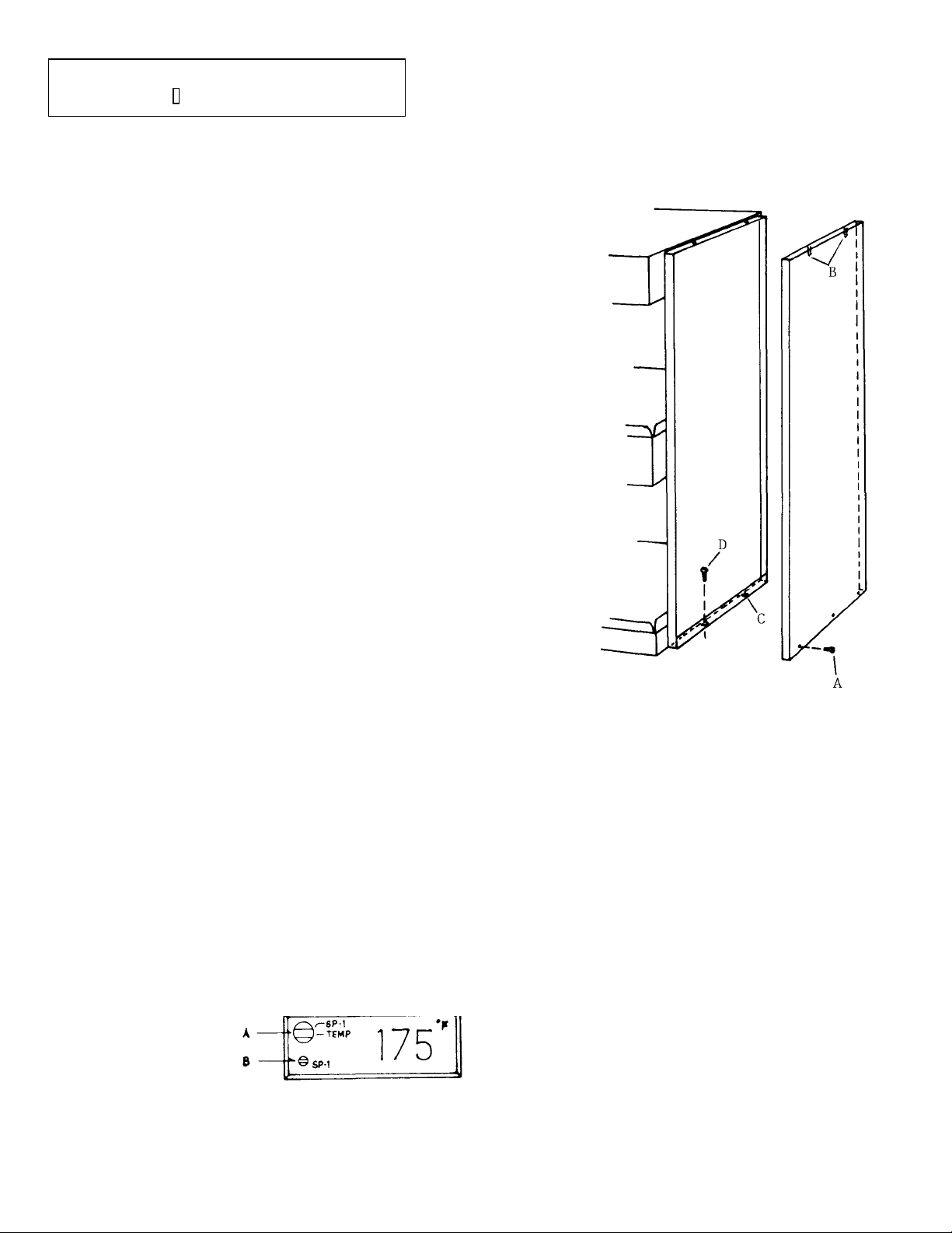
3. Position warmer on counter top in desired location. Remove
end panel screws (A) and pull lower part of end panel cover
out slightly from unit. Then lift panel cover until top pins (B)
clear holes. Drill holes in counter top to line up with holes
(C) in end panel base.
Anchor warmer to counter with screws (D) and provide a
silicone bead or other acceptable material to seal warmer to
counter (N.S.F. required). Replace end panel.
4. Connect warmer to power supply through appropriate
knockout opening. Use chase nipple provided in knockout
opening to protect wiring.
CAUTION: THIS WARMER IS FOR PASS-THRU
APPLICATIONS ONLY. DO NOT INSTALL
CLOSER THAN 3" TO A BACK WALL.
OPERATION & MAINTENANCE
OPERATION
To operate warmer, turn power switch "on". Place
temperature setpoint at desired level and wait until
temperature stabilizes. Plac e product in holding tray.
PROGRAMMING CONTROLLER
To set operating temperature, turn Mode Switch (A)
counterclockwise to
the SP-1 position.
Adjust Setpoint Knob
(B) to desired temperature and turn Mode Switch clockwise to the TEMP
position.
MAINTENANCE
The Dual Line Staging Shelf requires very little
maintenance if installed and operated in accordance
with the manufacturer's instructions. The only userreplacement item is the coated light bulb. Use
manufacturer's approved bulbs when replacing.
To clean warmer, use a soft cloth and mild cleaning
agent or a stainless steel cleaner (Do not use abrasive
cleaning materials). CAUTION: Unplug or disconnect
power to unit before cleaning or servicing.
Page 3

REPLACEMENT PARTS LIST
Model GRTB
-
39
ITEM DESCRIPTION PART NO. QTY.
1 Controlled Temp. Display 02-01-049 2
2 On-off Toggle Switch 02-19-016 1
3 Overhead Heating Element 02-08-238 2
4 Blanket Heating Element 02-05-227 2
5 Tape Element 02-05-127 1
6 24 Volt Relay 02-01-050 2
7 24 Volt Transformer (120V) 02-17-022 2
8 Coated Light Bulb 02-30-043 6
9 Light Bulb Socket 02-30-044 6
10 Half Size Coated Pan 04-15-140 10
11 Full Size Coated Pan 04-15-141 4
CONVERSION: LEFT HAND CONTROLS TO RIGHT
HAND
Internal wiring is arranged to permit the repositioning of
controls from left to right without disconnecting any wires.
1. Remove 12 screws (A), (5 top, 5 bottom, 1 each end)
from canopy and remove face plate (B).
2. Rotate face plate (B) 180° clockwise, (controls move
from left end to right end) and then refasten face plate
to canopy.
3. Remove 6 screws (C) on controller plate (D). Pull plate
4. Rotate controller plate 180° counter-clockwise (be
out until controller bodies clear opening in face plate.
careful not to scrape or damage wires). Insert controller
into face plate opening and refasten with screws.
Page 4

 Loading...