

Page 1
INSTALLATION MANUAL AND
REPLACEMENT PARTS LIST
29 and
TACO BELL DUAL LINE STAGING SHELF
Model GRTB-
Model GRTB-33
HATCO CORPORATION MILWAUKEE, WI 53215 (414) 671-6350
Page 2
INSTALLATION PROCEDURES
Model GRTB
-29 &
GRTB
-33
HEIGHT ADJ.
-
LESS THAN
2-7/8'
WARNING:
BE SURE POWER IS OFF AT MAIN CIRCUIT
HEIGHT ADJ.
-
MORE THAN
2-7/8"
Installation to be performed by
qualified service personnel only
BREAKER. COMPLETE ALL INSTALLATION
PROCEDURES BEFORE CONNECTING TO POWER
SUPPLY.
1. Establish position of warmer with respect to counter top and
overshelf.
2. When applicable, finish sheet metal alterations before final
positioning of warmer.
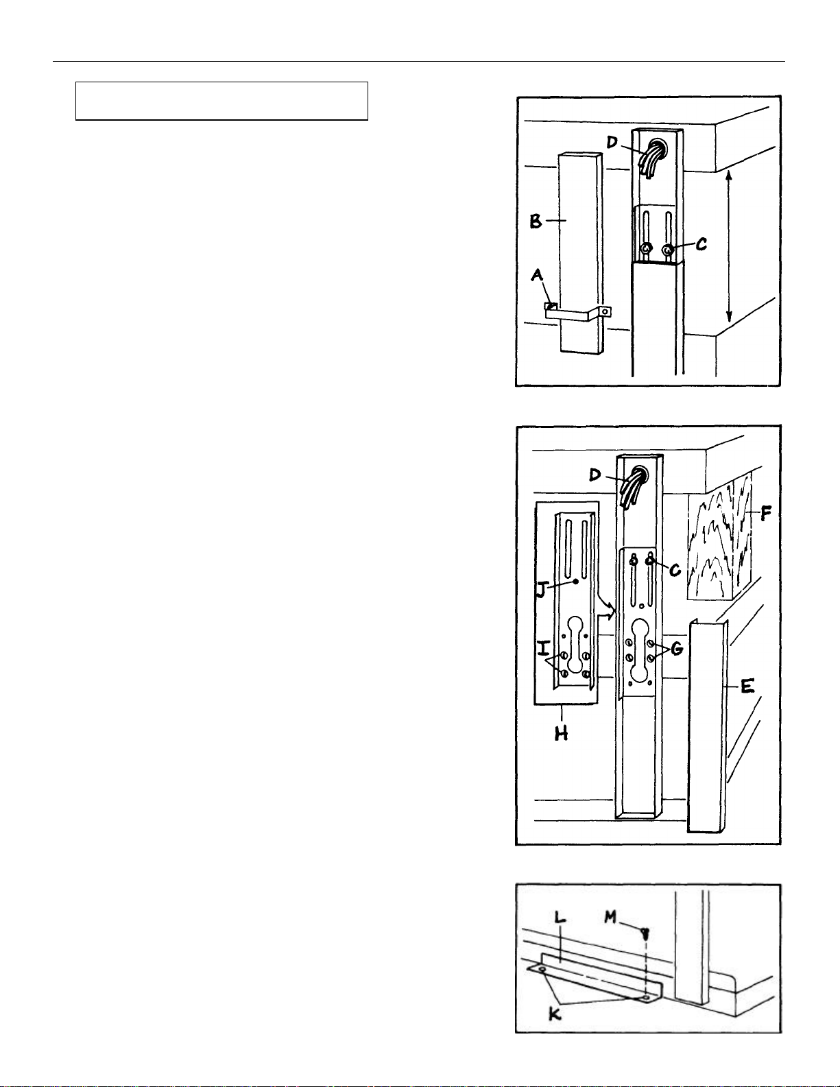
3. Adjust height of warmer using the following
methods: LESS THAN 2-7/8" - Remove tie straps (A) and upper
post covers (B). Loosen lock nuts (C) and carefully pull excess
wires (D) from top openings. Move top unit to height necessary to
align with overshelf and tighten lock nuts. Replace upper post
covers and tie straps.
MORE THAN 2-7/8" (Max. adjustment 4-7/8") -Remove tie straps (A)
and both upper (B) and lower (E) post covers. Block warmer (F)
between middle and upper unit to prevent upper unit from moving
(CAUTION - make sure unit is stable). Loosen lock nuts (C) and
remove screws (G) holding U-shaped channel, then raise channel to
upper position (H). Replace screws in new location (I) and tighten.
BE SURE TO DO THIS ONE CORNER AT A TIME. When all four Ushaped channels have been reposi-tioned, additional height
adjustment can be made by raising top section of warmer to desired
height and tightening lock nuts (C).
When final height adjustment has been made, drill through the pilot
hole (J) (3/16" dia.) in the U-shaped channels and into the post (BE
CAREFUL NOT TO DAMAGE WIRING - CLEAN OUT ALL METAL
FRAGMENTS). Anchor channel to post with a screw and cap nut
(welding is optional). Now replace lower (E) and upper (B) post
covers and tie straps (A).
4. On models GRTB -33, adjust two position angle bracket to align
with underside of overshelf.
COUNTER TOP MOUNTING
5. Position warmer on counter top and drill holes (K) to attach brackets
(L) to counter. Use screws (M) provided to anchor warmer to
counter top. Provide a silicone bead or other acceptable material to
seal warmer to counter (N.S.F. required).
6. Connect warmer to power supply through knock out opening.
Page 3

OPERATION
& MAINTENANCE
Model GRTB -29 & GRTB-33
12 Full Size Coated Pan
04-15-
141 *
OPERATION
To operate warmer, turn power switch "on". Place
temperature setpoint at desired level and wait until
temperature stabilizes. Place product in holding tray.
PROGRAMMING CONTROLLER
To set operating temperature, turn Mode
Switch (A) counterclockwise to the SP-1
position.
Adjust Setpoint A
Knob (B) to
desired temper- B
ature and turn
Mode Switch clockwise to the TEMP position.
REPLACEMENT PARTS LIST
MAINTENANCE
The Dual Line Staging Shelf requires very little
maintenance if installed and operated in accordance
with the manufacturer's instructions. The only userreplacement item is the coated light bulb. Use
manufacturer's approved bulbs when replacing.
To clean warmer, us e a soft cloth and mild cleaning
agent or a stainless steel cleaner (Do not use abrasive
cleaning materials). CAUTION: Unplug or disconnect
power to unit before cleaning or servicing.
ITEM DESCRIPTION PART NO. QTY.
1 Controlled Temp. Display 02-01-049 2
2 On-off Toggle Switch 02-19-016 1
3 Overhead Heating Element
Model GRTB -29 02-08-027 2
Model GRTB -33R & 33L 02-08-231 2
4 Blanket Heating Element
Model GRTB -29 02-05-203 2
Model GRTB -33R & 33L 02-05-202 2
5 Tape Element (all models) 02-05-098 1
6 24 Volt Relay 02-01-050 2
7 24 Volt Transformer (120V) 02-17-022 2
8 Coated Light Bulb 02-03-043 4-6
9 Light Bulb Socket 02-30-044 4-6
10 6 ft. Cord with Plug
(GRTB -29 only) 02-18-030 1
11 Half Size Coated Pan 04-15-140 *
* Quantity varies. Be sure to specify Half Size or Full Size.
Page 4

 Loading...