

Page 1
I&W #07.05.027.00
GLO-RAY
®
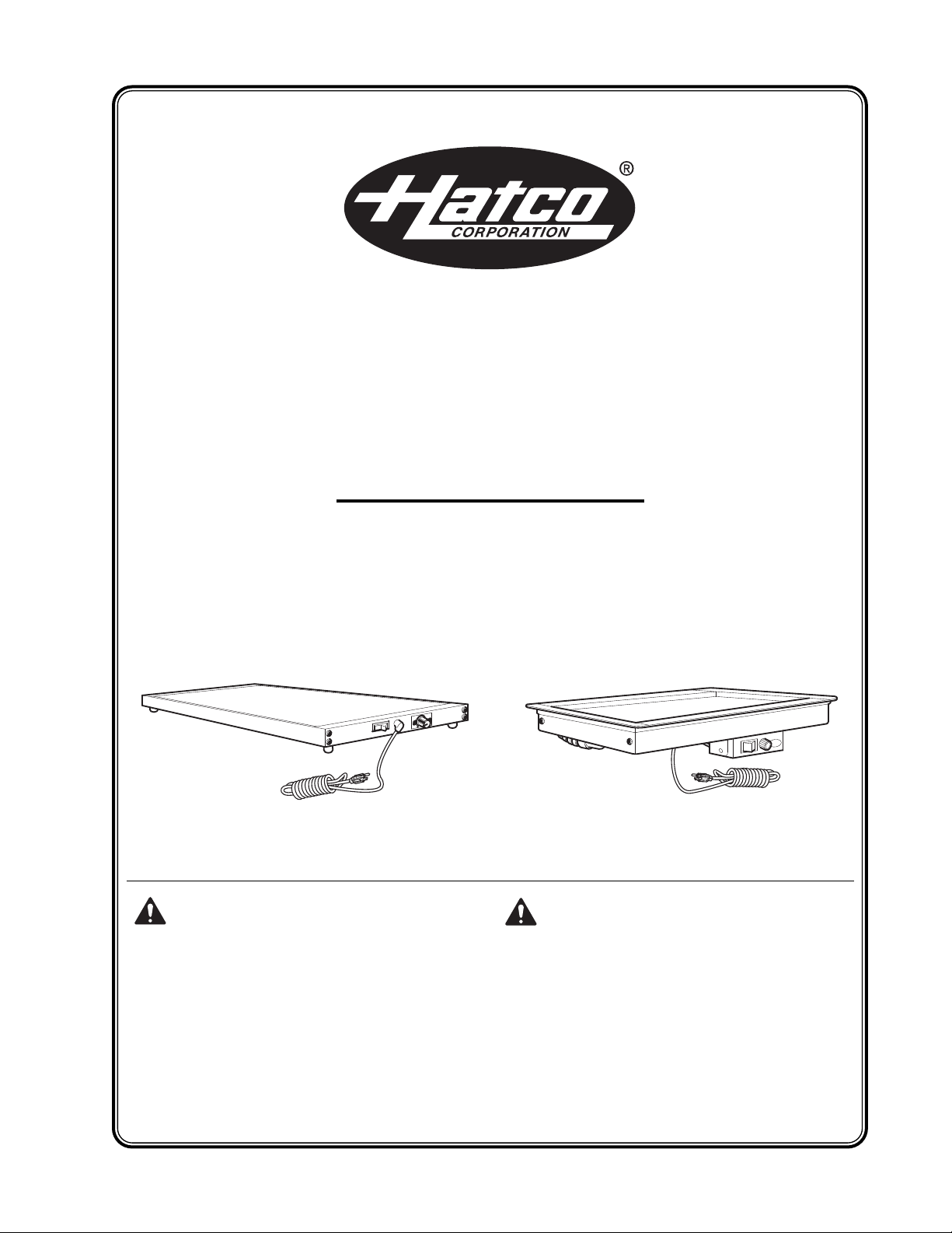
Heated Shelf
GRS, GRSB, and GRSBF Series
Installation and Operating Manual
Do not operate this equipment unless you
have read and understood the contents of
this manual! Failure to follow the
instructions contained in this manual may
result in serious injury or death. This
manual contains important safety
information concerning the maintenance,
use, and operation of this product. If
you’re unable to understand the contents
of this manual, please bring it to the
attention of your supervisor. Keep this
manual in a safe location for future
reference.
No opere este equipo al menos que haya
leído y comprendido el contenido de este
manual! Cualquier falla en el seguimiento
de las instrucciones contenidas en este
manual puede resultar en un serio lesión
o muerte. Este manual contiene
importante información sobre seguridad
concerniente al mantenimiento, uso y
operación de este producto. Si usted no
puede entender el contenido de este
manual por favor pregunte a su
supervisor. Almacenar este manual en
una localización segura para la referencia
futura.
© 2008 Hatco Corporation
Page 2
i
CONTENTS
Form No. GRSM-0108
INTRODUCTION
The Hatco Glo-Ray Heated Shelf is designed to
keep prepared foods hot in kitchen work areas,
server pick-up stations, or customer serving points.
It will keep all foods at optimum serving
temperatures without affecting quality. This warmer
has a thermostatically-controlled heated base to
extend the holding times of most foods.
Glo-Ray Heated Shelves are a product of extensive
research and field testing. The materials used were
selected for maximum durability, attractive
appearance, and optimum performance. Every unit
is inspected and tested thoroughly prior to shipment.
This manual provides the installation, safety, and
operating instructions for the Glo-Ray Heated Shelf.
Hatco recommends all installation, operating, and
safety instructions appearing in this manual be read
prior to installation or operation of the Glo-Ray
Heated Shelf.
Safety information that appears in this manual is
identified by the following signal word panels:
WARNING indicates a hazardous situation
which, if not avoided, could result in death or
serious injury.
CAUTION indicates a hazardous situation which,
if not avoided, could result in minor or moderate
injury.
NOTICE is used to address practices not related
to personal injury.
NOTICE
CAUTION
WARNING
Important Owner Information...............................i
Introduction ...........................................................i
Important Safety Information..............................1
Specifications.......................................................2
Plug Configurations .........................................2
Dimensions - GRS Models ..............................2
Dimensions - GRSB Models............................3
Dimensions - GRSBF Models .........................4
Electrical Rating Chart - GRS Models.............5
Electrical Rating Chart - GRSB Models ..........6
Electrical Rating Chart - GRSBF Models ........8
Model Descriptions............................................10
GRS Model ....................................................10
GRSB and GRSBF Models ...........................10
Model Designation .............................................10
Installation...........................................................11
GRS Models ..................................................11
GRSB and GRSBF Models ...........................11
Operation ............................................................15
Maintenance .......................................................16
Cleaning.........................................................16
Troubleshooting Guide......................................17
Accessories ........................................................18
Hatco Limited Warranty.....................................21
Authorized Parts Distributors...........Back Cover
IMPORTANT OWNER INFORMATION
Record the model number, serial number, voltage
and purchase date of your Glo-Ray®Heated Shelf in
the spaces below. Please have this information
available when contacting Hatco for service
assistance.
Model No. ____________________________________
Serial No. ____________________________________
Voltage ______________________________________
Date of Purchase ______________________________
Business 8:00 a.m. to 5:00 p.m.
Hours: Central Standard Time
(Summer Hours: June to September –
8:00 a.m. to 5:00 p.m. C.S.T.
Monday through Thursday
8:00 a.m. to 2:30 p.m. C.S.T. Friday)
Telephone: (800) 558-0607; (414) 671-6350
Fax: (800) 690-2966 (Parts and Service)
(414) 671-3976 (International)
24 Hour 7 Day Parts and Service
Assistance available in the
United States and Canada
by calling (800) 558-0607.
Additional information can be found by visiting our
web site at www.hatcocorp.com.
Page 3
IMPORTANT SAFETY INFORMATION
Form No. GRSM-0108
1
ELECTRIC SHOCK HAZARD:
• Plug unit into a properly grounded electrical
outlet of the correct voltage, size, and plug
configuration. If the plug and receptacle do
not match, contact a qualified electrician to
determine and install the proper voltage and
size electrical outlet.
• Turn the power switch OFF, unplug the power
cord, and allow the unit to cool before
performing any maintenance or cleaning.
• DO NOT submerge or saturate with water.
Unit is not waterproof. Do not operate if unit
has been submerged or saturated with water.
• Unit is not weatherproof. Locate the unit
indoors where the ambient air temperature is
a minimum of 70°F (21°C).
• Do not pull unit by power cord.
• Discontinue use if power cord is frayed or
worn.
• Do not attempt to repair or replace a
damaged power cord. The cord must be
replaced by Hatco, an Authorized Hatco
Service Agent, or a person with similar
qualifications.
• Use only Genuine Hatco Replacement Parts
when service is required. Failure to use
Genuine Hatco Replacement Parts may
subject operators of the equipment to
hazardous electrical voltage, resulting in
electrical shock or burn. Genuine Hatco
Replacement Parts are specified to operate
safely in the environments in which they are
used. Some aftermarket or generic
replacement parts do not have the
characteristics that will allow them to operate
safely in Hatco equipment.
FIRE HAZARD: Locate the unit a minimum of 1″
(25 mm) from combustible walls and materials. If
safe distances are not maintained, combustion
or discoloration could occur.
This unit has no “user-serviceable” parts. If
service is required on this unit, contact an
Authorized Hatco Service Agent or contact the
Hatco Service Department at 800-558-0607 or
414-671-6350; fax 800-690-2966; or International
fax 414-671-3976.
WARNING
BURN HAZARD: Some exterior surfaces on the
unit will get hot. Use caution when touching
these areas.
Locate the unit at the proper counter height in
an area that is convenient for use. The location
should be level to prevent the unit or its
contents from falling accidentally and strong
enough to support the weight of the unit and
contents.
Do not operate built-in models without the
control box mounted properly as described in
the installation instructions.
The National Sanitation Foundation (NSF)
requires that heated shelf units over 36″
(914 mm) in length or weighing more than
80 lbs. (36 kg) either be sealed to or raised
above the installation surface. If this unit cannot
be sealed at the point of use, 4″ (102 mm) legs
are included to allow for proper cleaning access
below unit. Refer to the ACCESSORIES section
for installation instructions.
This unit is recommended for use in metallic
countertops. Damage to non-metallic countertop
material caused by heat generated from Hatco
equipment is not covered under the Hatco
warranty. For other surfaces, verify that the
material is suitable for temperatures up to 200° F
(93° C).
Built-in units must not have a setpoint
temperature higher than 200°F (93°C).
Temperatures exceeding 200°F (93°C) will
damage the unit and void the warranty.
Use of excessive force when tightening
mounting screws of built-in units may damage
unit or countertop.
Do not lay unit on the side with the control panel
or damage to the unit could occur.
Use non-abrasive cleaners only. Abrasive
cleaners could scratch the finish of the unit,
marring its appearance and making it
susceptible to soil accumulation.
NOTICE
CAUTION
Read the following important safety information before using this equipment to avoid
serious injury or death and to avoid damage to equipment or property.
Page 4
SPECIFICATIONS
2
Form No. GRSM-0108
NEMA 5-15P NEMA 5-20P
NEMA 6-15P
CEE 7/7 Schuko BS-1363
NOTE: Receptacle not supplied by Hatco.
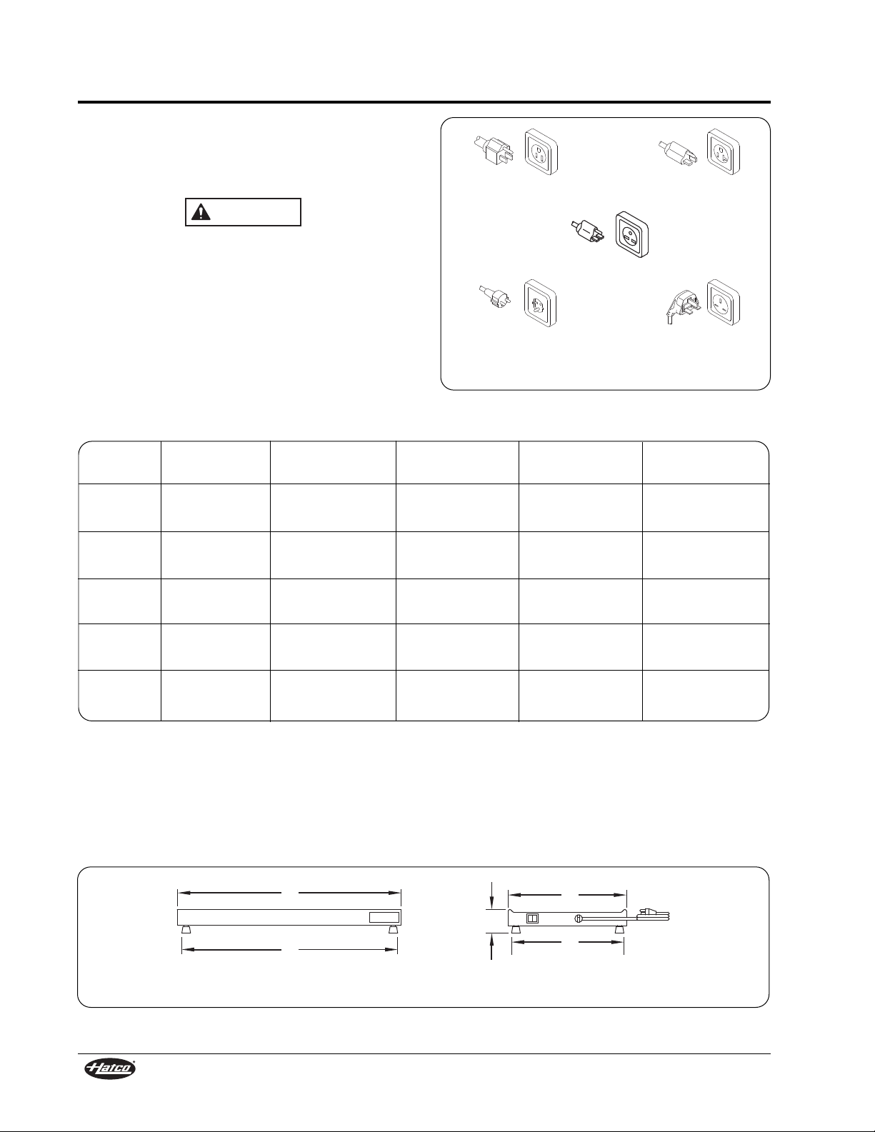
Figure 1. Plug Configurations
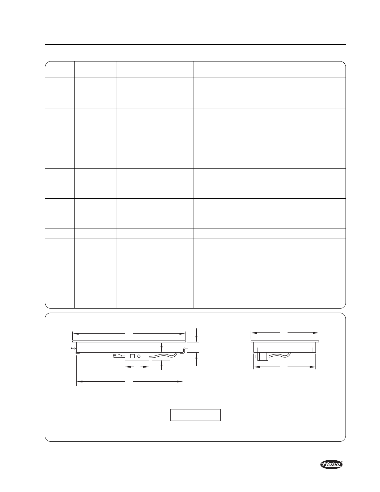
Figure 2. GRS Model Dimensions
Dimensions — GRS Models
Plug Configurations
Units are supplied from the factory with an electrical
cord and plug installed. Plugs are supplied
according to the applications as shown in Figure 1.
ELECTRIC SHOCK HAZARD: Plug unit into a
properly grounded electrical outlet of the correct
voltage, size, and plug configuration. If the plug
and receptacle do not match, contact a qualified
electrician to determine and install the proper
voltage and size electrical outlet.
WARNING
Footprint Footprint
Model Width (A) Depth (B) Height (C) Width (D) Depth (E)
GRS-18-I 18″ (457 mm) 19-1/2″ (495 mm) 2-1/4″ (57 mm)† 16-3/4″ (425 mm) 18″ (457 mm)
GRS-24-I 24″ (610 mm) 19-1/2″ (495 mm) 2-1/4″ (57 mm)† 22-3/4″ (578 mm) 18″ (457 mm)
GRS-30-I 30″ (762 mm) 19-1/2″ (495 mm) 2-1/4″ (57 mm)† 28-3/4″ (730 mm) 18″ (457 mm)
GRS-36-I 36″ (914 mm) 19-1/2″ (495 mm) 2-1/4″ (57 mm)† 34-3/4″ (883 mm) 18″ (457 mm)
GRS-42-I 42″ (1067 mm) 19-1/2″ (495 mm) 5-1/4″ (133 mm)* 40-3/4″ (1035 mm) 18″ (457 mm)
GRS-48-I 48″ (1219 mm) 19-1/2″ (495 mm) 5-1/4″ (133 mm)* 46-3/4″ (1187 mm) 18″ (457 mm)
GRS-54-I 54″ (1372 mm) 19-1/2″ (495 mm) 5-1/4″ (133 mm)* 52-3/4″ (1340 mm) 18″ (457 mm)
GRS-60-I 60″ (1524 mm) 19-1/2″ (495 mm) 5-1/4″ (133 mm)* 58-3/4″ (1492 mm) 18″ (457 mm)
GRS-66-I 66″ (1676 mm) 19-1/2″ (495 mm) 5-1/4″ (133 mm)* 64-3/4″ (1645 mm) 18″ (457 mm)
GRS-72-I 72″ (1829 mm) 19-1/2″ (495 mm) 5-1/4″ (133 mm)* 70-3/4″ (1797 mm) 18″ (457 mm)
A
D
B
E
C
Front View Side View
NOTE: All models listed above are based on 19-1/2″ (495 mm) depth. The additional depths available
include:
6″ (152 mm) 7-3/4″ (197 mm) 9-3/4″ (248 mm) 12″ (305 mm)
13-3/4″ (349 mm) 15-1/2″ (394 mm) 15-3/4″ (400 mm) 17-1/2″ (445 mm)
21-1/2″ (546 mm) 23-1/2″ (597 mm) 25-1/2″ (648 mm)
†Height includes 1″ (25 mm) legs.
*Height includes 4″ (102 mm) legs.
Page 5
SPECIFICATIONS
Form No. GRSM-0108
3
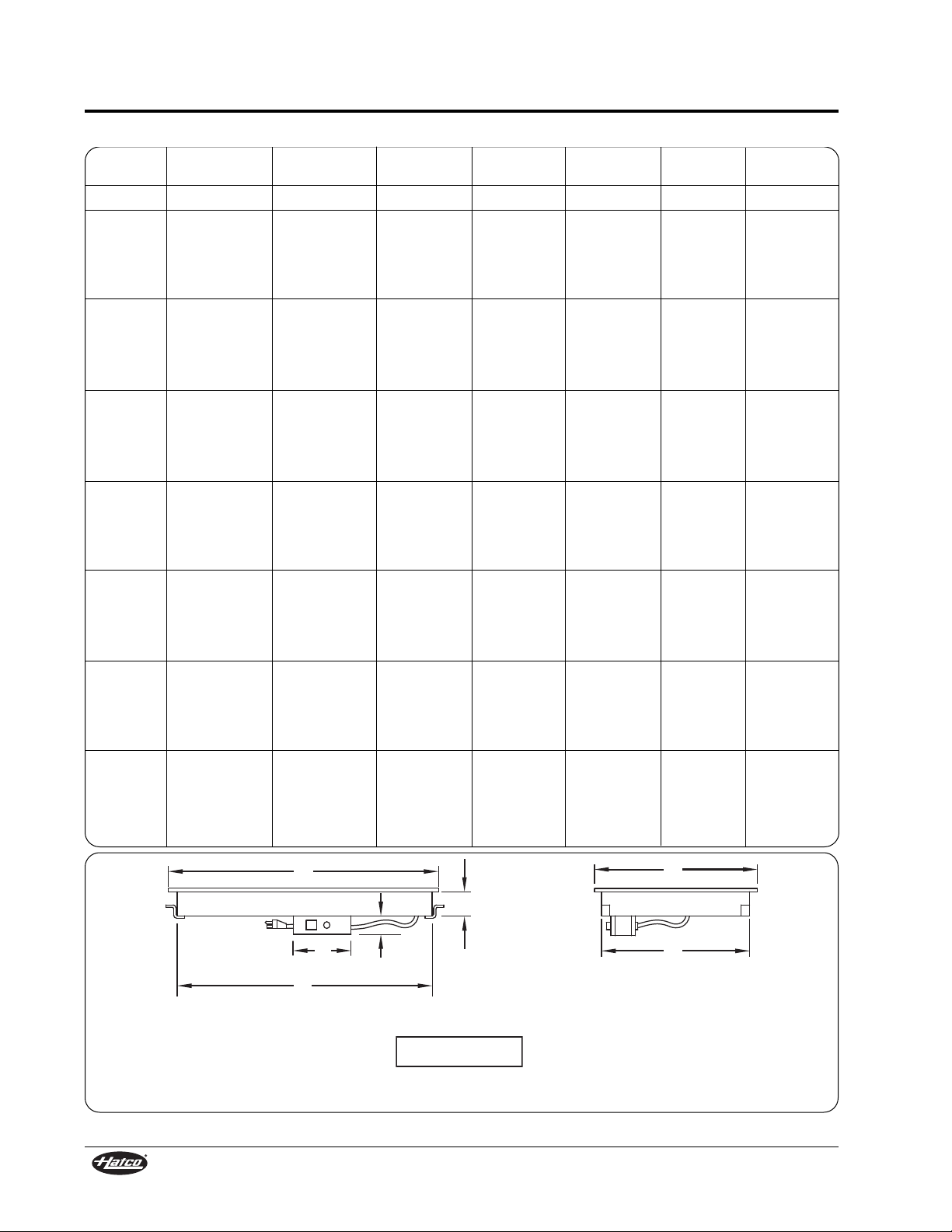
Overall Heated Heated Overall
Model Width (A) Width (B) Width (C) Depth (D) Depth (E) Height (F) Height (G)
GRSB-24-F 25-1/2″ (648 mm) 24″ (610 mm) 7-1/16″ (179 mm) 15-1/2″ (394 mm) 17″ (432 mm) 2-7/8″ (73 mm) 2-1/32″ (52 mm)
GRSB-24-I 25-1/2″ (648 mm) 24″ (610 mm) 7-1/16″ (179 mm) 19-1/2″ (495 mm) 21″ (533 mm) 2-7/8″ (73 mm) 2-1/32″ (52 mm)
GRSB-24-O 25-1/2″ (648 mm) 24″ (610 mm) 7-1/16″ (179 mm) 30″ (762 mm) 31-1/2″ (800 mm) 2-7/8″ (73 mm) 2-1/32″ (52 mm)
GRSB-30-F 31-1/2″ (800 mm) 30″ (762 mm) 7-1/16″ (179 mm) 15-1/2″ (394 mm) 17″ (432 mm) 2-7/8″ (73 mm) 2-1/32″ (52 mm)
GRSB-30-I 31-1/2″ (800 mm) 30″ (762 mm) 7-1/16″ (179 mm) 19-1/2″ (495 mm) 21″ (533 mm) 2-7/8″ (73 mm) 2-1/32″ (52 mm)
GRSB-30-O 31-1/2″ (800 mm) 30″ (762 mm) 7-1/16″ (179 mm) 30″ (762 mm) 31-1/2″ (800 mm) 2-7/8″ (73 mm) 2-1/32″ (52 mm)
GRSB-36-F 37-1/2″ (953 mm) 36″ (914 mm) 7-1/16″ (179 mm) 15-1/2″ (394 mm) 17″ (432 mm) 2-7/8″ (73 mm) 2-1/32″ (52 mm)
GRSB-36-I 37-1/2″ (953 mm) 36″ (914 mm) 7-1/16″ (179 mm) 19-1/2″ (495 mm) 21″ (533 mm) 2-7/8″ (73 mm) 2-1/32″ (52 mm)
GRSB-36-O 37-1/2″ (953 mm) 36″ (914 mm) 7-1/16″ (179 mm) 30″ (762 mm) 31-1/2″ (800 mm) 2-7/8″ (73 mm) 2-1/32″ (52 mm)
GRSB-42-F 43-1/2″ (1105 mm) 42″ (1067 mm) 7-1/16″ (179 mm) 15-1/2″ (394 mm) 17″ (432 mm) 2-7/8″ (73 mm) 2-1/32″ (52 mm)
GRSB-42-I 43-1/2″ (1105 mm) 42″ (1067 mm) 7-1/16″ (179 mm) 19-1/2″ (495 mm) 21″ (533 mm) 2-7/8″ (73 mm) 2-1/32″ (52 mm)
GRSB-42-O 43-1/2″ (1105 mm) 42″ (1067 mm) 7-1/16″ (179 mm) 30″ (762 mm) 31-1/2″ (800 mm) 2-7/8″ (73 mm) 2-1/32″ (52 mm)
GRSB-48-F 49-1/2″ (1257 mm) 48″ (1219 mm) 7-1/16″ (179 mm) 15-1/2″ (394 mm) 17″ (432 mm) 2-7/8″ (73 mm) 2-1/32″ (52 mm)
GRSB-48-I 49-1/2″ (1257 mm) 48″ (1219 mm) 7-1/16″ (179 mm) 19-1/2″ (495 mm) 21″ (533 mm) 2-7/8″ (73 mm) 2-1/32″ (52 mm)
GRSB-48-O 49-1/2″ (1257 mm) 48″ (1219 mm) 7-1/16″ (179 mm) 30″ (762 mm) 31-1/2″ (800 mm) 2-7/8″ (73 mm) 2-1/32″ (52 mm)
GRSB-54-I 55-1/2″ (1410 mm) 54″ (1372 mm) 7-1/16″ (179 mm) 19-1/2″ (495 mm) 21″ (533 mm) 2-7/8″ (73 mm) 2-1/32″ (52 mm)
GRSB-60-F 61-1/2″ (1562 mm) 60″ (1524 mm) 7-1/16″ (179 mm) 15-1/2″ (394 mm) 17″ (432 mm) 2-7/8″ (73 mm) 2-1/32″ (52 mm)
GRSB-60-I 61-1/2″ (1562 mm) 60″ (1524 mm) 7-1/16″ (179 mm) 19-1/2″ (495 mm) 21″ (533 mm) 2-7/8″ (73 mm) 2-1/32″ (52 mm)
GRSB-60-O 61-1/2″ (1562 mm) 60″ (1524 mm) 7-1/16″ (179 mm) 30″ (762 mm) 31-1/2″ (800 mm) 2-7/8″ (73 mm) 2-1/32″ (52 mm)
GRSB-66-I 67-1/2″ (1715 mm) 66″ (1676 mm) 7-1/16″ (179 mm) 19-1/2″ (495 mm) 21″ (533 mm) 2-7/8″ (73 mm) 2-1/32″ (52 mm)
GRSB-72-F 73-1/2″ (1867 mm) 72″ (1829 mm) 7-1/16″ (179 mm) 15-1/2″ (394 mm) 17″ (432 mm) 2-7/8″ (73 mm) 2-1/32″ (52 mm)
GRSB-72-I 73-1/2″ (1867 mm) 72″ (1829 mm) 7-1/16″ (179 mm) 19-1/2″ (495 mm) 21″ (533 mm) 2-7/8″ (73 mm) 2-1/32″ (52 mm)
GRSB-72-O 73-1/2″ (1867 mm) 72″ (1829 mm) 7-1/16″ (179 mm) 30″ (762 mm) 31-1/2″ (800 mm) 2-7/8″ (73 mm) 2-1/32″ (52 mm)
A
B
E
D
C
F
G
Front View Side View
Dimensions — GRSB Models
Refer to the INSTALLATION section of this
manual for actual countertop cutout dimensions.
NOTICE
Figure 3. GRSB Model Dimensions
Page 6
SPECIFICATIONS
4
Form No. GRSM-0108
Heated Heated
Model Width (A) Width (B) Width (C) Depth (D) Depth (E) Height (F) Height (G)
GRSBF-18-F 19-1/2″ (495 mm) 18-3/32″ (460 mm) 7-1/16″ (179 mm) 15-1/2″ (394 mm) 17″ (432 mm) 2-1/4″ (57 mm) 2-1/32″ (52 mm)
GRSBF-24-F 25-1/2″ (648 mm) 24-3/32″ (612 mm) 7-1/16″ (179 mm) 15-1/2″ (394 mm) 17″ (432 mm) 2-1/4″ (57 mm) 2-1/32″ (52 mm)
GRSBF-24-I 25-1/2″ (648 mm) 24-3/32″ (612 mm) 7-1/16″ (179 mm) 19-1/2″ (495 mm) 21″ (533 mm) 2-1/4″ (57 mm) 2-1/32″ (52 mm)
GRSBF-24-S 25-1/2″ (648 mm) 24-3/32″ (612 mm) 7-1/16″ (179 mm) 24″ (610 mm) 25-1/2″ (648 mm) 2-1/4″ (57 mm) 2-1/32″ (52 mm)
GRSBF-24-O 25-1/2″ (648 mm) 24-3/32″ (612 mm) 7-1/16″ (179 mm) 30″ (762 mm) 31-1/2″ (800 mm) 2-1/4″ (57 mm) 2-1/32″ (52 mm)
GRSBF-30-F 31-1/2″ (800 mm) 30-3/32″ (764 mm) 7-1/16″ (179 mm) 15-1/2″ (394 mm) 17″ (432 mm) 2-1/4″ (57 mm) 2-1/32″ (52 mm)
GRSBF-30-I 31-1/2″ (800 mm) 30-3/32″ (764 mm) 7-1/16″ (179 mm) 19-1/2″ (495 mm) 21″ (533 mm) 2-1/4″ (57 mm) 2-1/32″ (52 mm)
GRSBF-30-S 31-1/2″ (800 mm) 30-3/32″ (764 mm) 7-1/16″ (179 mm) 24″ (610 mm) 25-1/2″ (648 mm) 2-1/4″ (57 mm) 2-1/32″ (52 mm)
GRSBF-30-O 31-1/2″ (800 mm) 30-3/32″ (764 mm) 7-1/16″ (179 mm) 30″ (762 mm) 31-1/2″ (800 mm) 2-1/4″ (57 mm) 2-1/32″ (52 mm)
GRSBF-36-F 37-1/2″ (953 mm) 36-3/32″ (917 mm) 7-1/16″ (179 mm) 15-1/2″ (394 mm) 17″ (432 mm) 2-1/4″ (57 mm) 2-1/32″ (52 mm)
GRSBF-36-I 37-1/2″ (953 mm) 36-3/32″ (917 mm) 7-1/16″ (179 mm) 19-1/2″ (495 mm) 21″ (533 mm) 2-1/4″ (57 mm) 2-1/32″ (52 mm)
GRSBF-36-S 37-1/2″ (953 mm) 36-3/32″ (917 mm) 7-1/16″ (179 mm) 24″ (610 mm) 25-1/2″ (648 mm) 2-1/4″ (57 mm) 2-1/32″ (52 mm)
GRSBF-36-O 37-1/2″ (953 mm) 36-3/32″ (917 mm) 7-1/16″ (179 mm) 30″ (762 mm) 31-1/2″ (800 mm) 2-1/4″ (57 mm) 2-1/32″ (52 mm)
GRSBF-42-F 43-1/2″ (1105 mm) 42-3/32″ (1069 mm) 7-1/16″ (179 mm) 15-1/2″ (394 mm) 17″ (432 mm) 2-1/4″ (57 mm) 2-1/32″ (52 mm)
GRSBF-42-I 43-1/2″ (1105 mm) 42-3/32″ (1069 mm) 7-1/16″ (179 mm) 19-1/2″ (495 mm) 21″ (533 mm) 2-1/4″ (57 mm) 2-1/32″ (52 mm)
GRSBF-42-S 43-1/2″ (1105 mm) 42-3/32″ (1069 mm) 7-1/16″ (179 mm) 24″ (610 mm) 25-1/2″ (648 mm) 2-1/4″ (57 mm) 2-1/32″ (52 mm)
GRSBF-42-O 43-1/2″ (1105 mm) 42-3/32″ (1069 mm) 7-1/16″ (179 mm) 30″ (762 mm) 31-1/2″ (800 mm) 2-1/4″ (57 mm) 2-1/32″ (52 mm)
GRSBF-48-F 49-1/2″ (1257 mm) 48-3/32″ (1222 mm) 7-1/16″ (179 mm) 15-1/2″ (394 mm) 17″ (432 mm) 2-1/4″ (57 mm) 2-1/32″ (52 mm)
GRSBF-48-I 49-1/2″ (1257 mm) 48-3/32″ (1222 mm) 7-1/16″ (179 mm) 19-1/2″ (495 mm) 21″ (533 mm) 2-1/4″ (57 mm) 2-1/32″ (52 mm)
GRSBF-48-S 49-1/2″ (1257 mm) 48-3/32″ (1222 mm) 7-1/16″ (179 mm) 24″ (610 mm) 25-1/2″ (648 mm) 2-1/4″ (57 mm) 2-1/32″ (52 mm)
GRSBF-48-O 49-1/2″ (1257 mm) 48-3/32″ (1222 mm) 7-1/16″ (179 mm) 30″ (762 mm) 31-1/2″ (800 mm) 2-1/4″ (57 mm) 2-1/32″ (52 mm)
GRSBF-60-F 61-1/2″ (1562 mm) 60- 3/32″ (1526 mm) 7-1/16″ (179 mm) 15-1/2″ (394 mm) 17″ (432 mm) 2-1/4″ (57 mm) 2-1/32″ (52 mm)
GRSBF-60-I 61-1/2″ (1562 mm) 60-3/32″ (1526 mm) 7-1/16″ (179 mm) 19-1/2″ (495 mm) 21″ (533 mm) 2-1/4″ (57 mm) 2-1/32″ (52 mm)
GRSBF-60-S 61-1/2″ (1562 mm) 60- 3/32″ (1526 mm) 7-1/16″ (179 mm) 24″ (610 mm) 25-1/2″ (648 mm) 2-1/4″ (57 mm) 2-1/32″ (52 mm)
GRSBF-60-O 61-1/2″ (1562 mm) 60 -3/32″ (1526 mm) 7-1/16″ (179 mm) 30″ (762 mm) 31-1/2″ (800 mm) 2-1/4″ (57 mm) 2-1/32″ (52 mm)
GRSBF-72-F 73-1/2″ (1867 mm) 72-3/32″ (1831 mm) 7-1/16″ (179 mm) 15-1/2″ (394 mm) 17″ (432 mm) 2-1/4″ (57 mm) 2-1/32″ (52 mm)
GRSBF-72-I 73-1/2″ (1867 mm) 72-3/32″ (1831 mm) 7-1/16″ (179 mm) 19-1/2″ (495 mm) 21″ (533 mm) 2-1/4″ (57 mm) 2-1/32″ (52 mm)
GRSBF-72-S 73-1/2″ (1867 mm) 72-3/32″ (1831 mm) 7-1/16″ (179 mm) 24″ (610 mm) 25-1/2″ (648 mm) 2-1/4″ (57 mm) 2-1/32″ (52 mm)
GRSBF-72-O 73-1/2″ (1867 mm) 72-3/32″ (1831 mm) 7-1/16″ (179 mm) 30″ (762 mm) 31-1/2″ (800 mm) 2-1/4″ (57 mm) 2-1/32″ (52 mm)
A
B
E
D
C
F
G
Front View Side View
Dimensions — GRSBF Models
Figure 4. GRSBF Model Dimensions
Refer to the INSTALLATION section of this
manual for actual countertop cutout dimensions.
NOTICE
Page 7
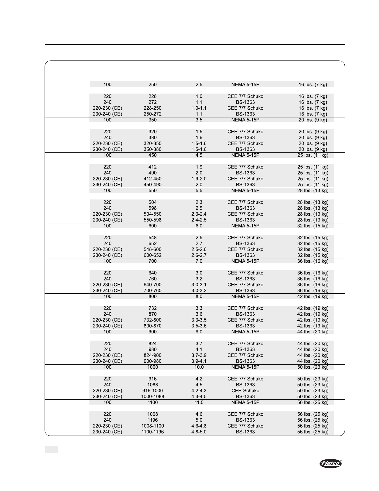
Plug Shipping
Model
†
Voltage Watts Amps Configuration Weight
GRS-18-I 100 250 2.5 NEMA 5-15P 16 lbs. (7 kg)
120 250 2.1 NEMA 5-15P 16 lbs. (7 kg)
220 228 1.0 CEE 7/7 Schuko 16 lbs. (7 kg)
240 272 1.1 BS-1363 16 lbs. (7 kg)
220-230 (CE) 228-250 1.0-1.1 CEE 7/7 Schuko 16 lbs. (7 kg)
230-240 (CE) 250-272 1.1 BS-1363 16 lbs. (7 kg)
GRS-24-I 100 350 3.5 NEMA 5-15P 20 lbs. (9 kg)
120 350 2.9 NEMA 5-15P 20 lbs. (9 kg)
220 320 1.5 CEE 7/7 Schuko 20 lbs. (9 kg)
240 380 1.6 BS-1363 20 lbs. (9 kg)
220-230 (CE) 320-350 1.5-1.6 CEE 7/7 Schuko 20 lbs. (9 kg)
230-240 (CE) 350-380 1.5-1.6 BS-1363 20 lbs. (9 kg)
GRS-30-I 100 450 4.5 NEMA 5-15P 25 lbs. (11 kg)
120 450 3.8 NEMA 5-15P 25 lbs. (11 kg)
220 412 1.9 CEE 7/7 Schuko 25 lbs. (11 kg)
240 490 2.0 BS-1363 25 lbs. (11 kg)
220-230 (CE) 412-450 1.9-2.0 CEE 7/7 Schuko 25 lbs. (11 kg)
230-240 (CE) 450-490 2.0 BS-1363 25 lbs. (11 kg)
GRS-36-I 100 550 5.5 NEMA 5-15P 28 lbs. (13 kg)
120 550 4.6 NEMA 5-15P 28 lbs. (13 kg)
220 504 2.3 CEE 7/7 Schuko 28 lbs. (13 kg)
240 598 2.5 BS-1363 28 lbs. (13 kg)
220-230 (CE) 504-550 2.3-2.4 CEE 7/7 Schuko 28 lbs. (13 kg)
230-240 (CE) 550-598 2.4-2.5 BS-1363 28 lbs. (13 kg)
GRS-42-I 100 600 6.0 NEMA 5-15P 32 lbs. (15 kg)
120 600 5.0 NEMA 5-15P 32 lbs. (15 kg)
220 548 2.5 CEE 7/7 Schuko 32 lbs. (15 kg)
240 652 2.7 BS-1363 32 lbs. (15 kg)
220-230 (CE) 548-600 2.5-2.6 CEE 7/7 Schuko 32 lbs. (15 kg)
230-240 (CE) 600-652 2.6-2.7 BS-1363 32 lbs. (15 kg)
GRS-48-I 100 700 7.0 NEMA 5-15P 36 lbs. (16 kg)
120 700 5.8 NEMA 5-15P 36 lbs. (16 kg)
220 640 3.0 CEE 7/7 Schuko 36 lbs. (16 kg)
240 760 3.2 BS-1363 36 lbs. (16 kg)
220-230 (CE) 640-700 3.0-3.1 CEE 7/7 Schuko 36 lbs. (16 kg)
230-240 (CE) 700-760 3.0-3.2 BS-1363 36 lbs. (16 kg)
GRS-54-I 100 800 8.0 NEMA 5-15P 42 lbs. (19 kg)
120 800 6.7 NEMA 5-15P 42 lbs. (19 kg)
220 732 3.3 CEE 7/7 Schuko 42 lbs. (19 kg)
240 870 3.6 BS-1363 42 lbs. (19 kg)
220-230 (CE) 732-800 3.3-3.5 CEE 7/7 Schuko 42 lbs. (19 kg)
230-240 (CE) 800-870 3.5-3.6 BS-1363 42 lbs. (19 kg)
GRS-60-I 100 900 9.0 NEMA 5-15P 44 lbs. (20 kg)
120 900 7.5 NEMA 5-15P 44 lbs. (20 kg)
220 824 3.7 CEE 7/7 Schuko 44 lbs. (20 kg)
240 980 4.1 BS-1363 44 lbs. (20 kg)
220-230 (CE) 824-900 3.7-3.9 CEE 7/7 Schuko 44 lbs. (20 kg)
230-240 (CE) 900-980 3.9-4.1 BS-1363 44 lbs. (20 kg)
GRS-66-I 100 1000 10.0 NEMA 5-15P 50 lbs. (23 kg)
120 1000 8.3 NEMA 5-15P 50 lbs. (23 kg)
220 916 4.2 CEE 7/7 Schuko 50 lbs. (23 kg)
240 1088 4.5 BS-1363 50 lbs. (23 kg)
220-230 (CE) 916-1000 4.2-4.3 CEE-Schuko 50 lbs. (23 kg)
230-240 (CE) 1000-1088 4.3-4.5 BS-1363 50 lbs. (23 kg)
GRS-72-I 100 1100 11.0 NEMA 5-15P 56 lbs. (25 kg)
120 1100 9.2 NEMA 5-15P 56 lbs. (25 kg)
220 1008 4.6 CEE 7/7 Schuko 56 lbs. (25 kg)
240 1196 5.0 BS-1363 56 lbs. (25 kg)
220-230 (CE) 1008-1100 4.6-4.8 CEE 7/7 Schuko 56 lbs. (25 kg)
230-240 (CE) 1100-1196 4.8-5.0 BS-1363 56 lbs. (25 kg)
SPECIFICATIONS
Form No. GRSM-0108
5
† All GRS models listed are based on 19-1/2″ (495 mm) heated depth. Additional depths available.
The shaded areas contain electrical information for Export models only.
Electrical Rating Chart — Standard GRS Models
Page 8
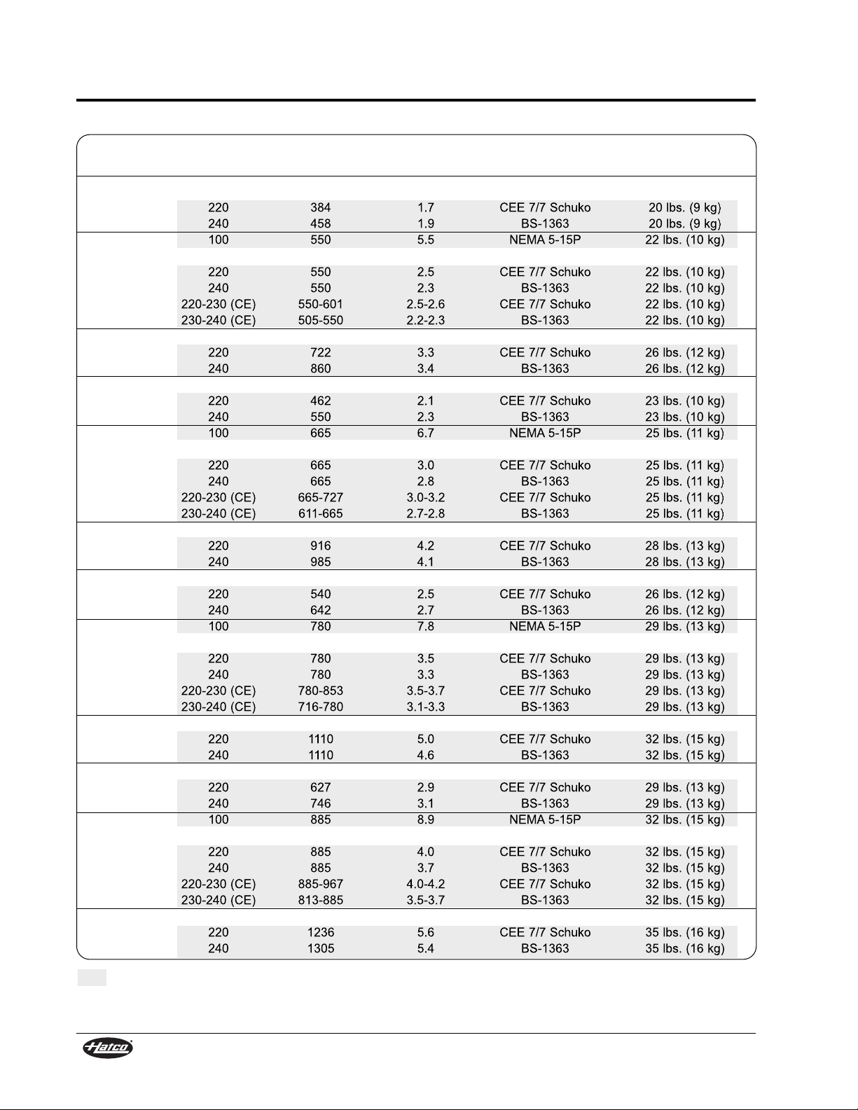
Plug Shipping
Model Voltage Watts Amps Configuration Weight
GRSB-24-F 120 420 3.5 NEMA 5-15P 20 lbs. (9 kg)
220 384 1.7 CEE 7/7 Schuko 20 lbs. (9 kg)
240 458 1.9 BS-1363 20 lbs. (9 kg)
GRSB-24-I 100 550 5.5 NEMA 5-15P 22 lbs. (10 kg)
120 550 4.6 NEMA 5-15P 22 lbs. (10 kg)
220 550 2.5 CEE 7/7 Schuko 22 lbs. (10 kg)
240 550 2.3 BS-1363 22 lbs. (10 kg)
220-230 (CE) 550-601 2.5-2.6 CEE 7/7 Schuko 22 lbs. (10 kg)
230-240 (CE) 505-550 2.2-2.3 BS-1363 22 lbs. (10 kg)
GRSB-24-O 120 790 6.6 NEMA 5-15P 26 lbs. (12 kg)
220 722 3.3 CEE 7/7 Schuko 26 lbs. (12 kg)
240 860 3.4 BS-1363 26 lbs. (12 kg)
GRSB-30-F 120 505 4.2 NEMA 5-15P 23 lbs. (10 kg)
220 462 2.1 CEE 7/7 Schuko 23 lbs. (10 kg)
240 550 2.3 BS-1363 23 lbs. (10 kg)
GRSB-30-I 100 665 6.7 NEMA 5-15P 25 lbs. (11 kg)
120 665 5.6 NEMA 5-15P 25 lbs. (11 kg)
220 665 3.0 CEE 7/7 Schuko 25 lbs. (11 kg)
240 665 2.8 BS-1363 25 lbs. (11 kg)
220-230 (CE) 665-727 3.0-3.2 CEE 7/7 Schuko 25 lbs. (11 kg)
230-240 (CE) 611-665 2.7-2.8 BS-1363 25 lbs. (11 kg)
GRSB-30-O 120 950 7.9 NEMA 5-15P 28 lbs. (13 kg)
220 916 4.2 CEE 7/7 Schuko 28 lbs. (13 kg)
240 985 4.1 BS-1363 28 lbs. (13 kg)
GRSB-36-F 120 590 4.9 NEMA 5-15P 26 lbs. (12 kg)
220 540 2.5 CEE 7/7 Schuko 26 lbs. (12 kg)
240 642 2.7 BS-1363 26 lbs. (12 kg)
GRSB-36-I 100 780 7.8 NEMA 5-15P 29 lbs. (13 kg)
120 780 6.5 NEMA 5-15P 29 lbs. (13 kg)
220 780 3.5 CEE 7/7 Schuko 29 lbs. (13 kg)
240 780 3.3 BS-1363 29 lbs. (13 kg)
220-230 (CE) 780-853 3.5-3.7 CEE 7/7 Schuko 29 lbs. (13 kg)
230-240 (CE) 716-780 3.1-3.3 BS-1363 29 lbs. (13 kg)
GRSB-36-O 120 1110 9.3 NEMA 5-15P 32 lbs. (15 kg)
220 1110 5.0 CEE 7/7 Schuko 32 lbs. (15 kg)
240 1110 4.6 BS-1363 32 lbs. (15 kg)
GRSB-42-F 120 685 5.7 NEMA 5-15P 29 lbs. (13 kg)
220 627 2.9 CEE 7/7 Schuko 29 lbs. (13 kg)
240 746 3.1 BS-1363 29 lbs. (13 kg)
GRSB-42-I 100 885 8.9 NEMA 5-15P 32 lbs. (15 kg)
120 885 7.4 NEMA 5-15P 32 lbs. (15 kg)
220 885 4.0 CEE 7/7 Schuko 32 lbs. (15 kg)
240 885 3.7 BS-1363 32 lbs. (15 kg)
220-230 (CE) 885-967 4.0-4.2 CEE 7/7 Schuko 32 lbs. (15 kg)
230-240 (CE) 813-885 3.5-3.7 BS-1363 32 lbs. (15 kg)
GRSB-42-O 120 1270 10.6 NEMA 5-15P 35 lbs. (16 kg)
220 1236 5.6 CEE 7/7 Schuko 35 lbs. (16 kg)
240 1305 5.4 BS-1363 35 lbs. (16 kg)
SPECIFICATIONS
6
Form No. GRSM-0108
Electrical Rating Chart — Standard GRSB Models
The shaded areas contain electrical information for Export models only.
Page 9
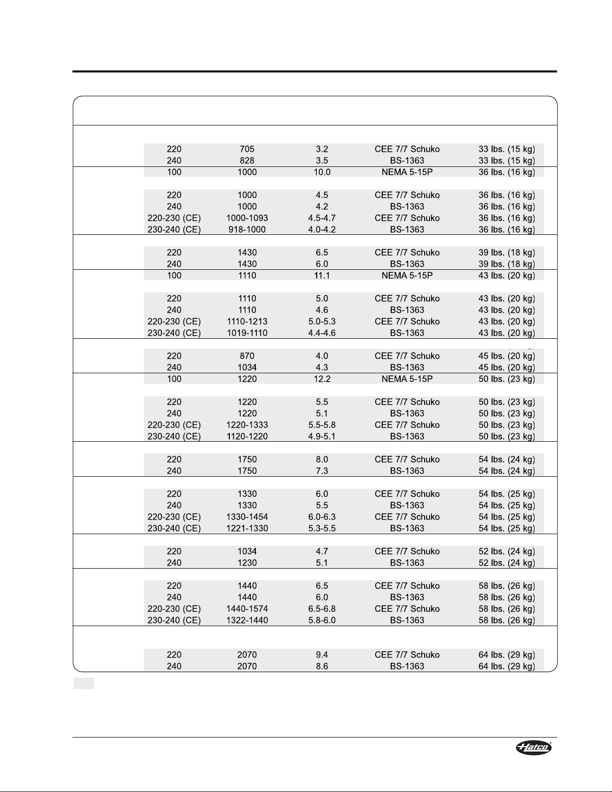
Plug Shipping
Model Voltage Watts Amps Configuration Weight
GRSB-48-F 120 770 6.4 NEMA 5-15P 33 lbs. (15 kg)
220 705 3.2 CEE 7/7 Schuko 33 lbs. (15 kg)
240 828 3.5 BS-1363 33 lbs. (15 kg)
GRSB-48-I 100 1000 10.0 NEMA 5-15P 36 lbs. (16 kg)
120 1000 8.3 NEMA 5-15P 36 lbs. (16 kg)
220 1000 4.5 CEE 7/7 Schuko 36 lbs. (16 kg)
240 1000 4.2 BS-1363 36 lbs. (16 kg)
220-230 (CE) 1000-1093 4.5-4.7 CEE 7/7 Schuko 36 lbs. (16 kg)
230-240 (CE) 918-1000 4.0-4.2 BS-1363 36 lbs. (16 kg)
GRSB-48-O 120 1430 11.9 NEMA 5-15P 39 lbs. (18 kg)
220 1430 6.5 CEE 7/7 Schuko 39 lbs. (18 kg)
240 1430 6.0 BS-1363 39 lbs. (18 kg)
GRSB-54-I 100 1110 11.1 NEMA 5-15P 43 lbs. (20 kg)
120 1110 9.3 NEMA 5-15P 43 lbs. (20 kg)
220 1110 5.0 CEE 7/7 Schuko 43 lbs. (20 kg)
240 1110 4.6 BS-1363 43 lbs. (20 kg)
220-230 (CE) 1110-1213 5.0-5.3 CEE 7/7 Schuko 43 lbs. (20 kg)
230-240 (CE) 1019-1110 4.4-4.6 BS-1363 43 lbs. (20 kg)
GRSB-60-F 120 950 7.9 NEMA 5-15P 45 lbs. (20 kg)
220 870 4.0 CEE 7/7 Schuko 45 lbs. (20 kg)
240 1034 4.3 BS-1363 45 lbs. (20 kg)
GRSB-60-I 100 1220 12.2 NEMA 5-15P 50 lbs. (23 kg)
120 1220 10.2 NEMA 5-15P 50 lbs. (23 kg)
220 1220 5.5 CEE 7/7 Schuko 50 lbs. (23 kg)
240 1220 5.1 BS-1363 50 lbs. (23 kg)
220-230 (CE) 1220-1333 5.5-5.8 CEE 7/7 Schuko 50 lbs. (23 kg)
230-240 (CE) 1120-1220 4.9-5.1 BS-1363 50 lbs. (23 kg)
GRSB-60-O 120 1750 14.6 NEMA 5-20P 54 lbs. (24 kg)
220 1750 8.0 CEE 7/7 Schuko 54 lbs. (24 kg)
240 1750 7.3 BS-1363 54 lbs. (24 kg)
GRSB-66-I 120 1330 11.1 NEMA 5-15P 54 lbs. (25 kg)
220 1330 6.0 CEE 7/7 Schuko 54 lbs. (25 kg)
240 1330 5.5 BS-1363 54 lbs. (25 kg)
220-230 (CE) 1330-1454 6.0-6.3 CEE 7/7 Schuko 54 lbs. (25 kg)
230-240 (CE) 1221-1330 5.3-5.5 BS-1363 54 lbs. (25 kg)
GRSB-72-F 120 1130 9.4 NEMA 5-15P 52 lbs. (24 kg)
220 1034 4.7 CEE 7/7 Schuko 52 lbs. (24 kg)
240 1230 5.1 BS-1363 52 lbs. (24 kg)
GRSB-72-I 120 1440 12.0 NEMA 5-15P 58 lbs. (26 kg)
220 1440 6.5 CEE 7/7 Schuko 58 lbs. (26 kg)
240 1440 6.0 BS-1363 58 lbs. (26 kg)
220-230 (CE) 1440-1574 6.5-6.8 CEE 7/7 Schuko 58 lbs. (26 kg)
230-240 (CE) 1322-1440 5.8-6.0 BS-1363 58 lbs. (26 kg)
GRSB-72-O 208 2070 10.0 NEMA 6-15P 64 lbs. (29 kg)
240 2070 8.6 NEMA 6-15P 64 lbs. (29 kg)
220 2070 9.4 CEE 7/7 Schuko 64 lbs. (29 kg)
240 2070 8.6 BS-1363 64 lbs. (29 kg)
SPECIFICATIONS
Form No. GRSM-0108
7
Electrical Rating Chart — Standard GRSB Models
The shaded areas contain electrical information for Export models only.
Page 10
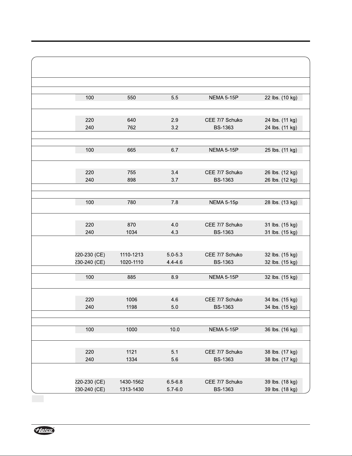
Plug Shipping
Model Voltage Watts Amps Configuration Weight
GRSBF-18-F 120 330 2.8 NEMA 5-15P 15 lbs. (7 kg)
GRSBF-24-F 120 420 3.5 NEMA 5-15P 20 lbs. (9 kg)
GRSBF-24-I 100 550 5.5 NEMA 5-15P 22 lbs. (10 kg)
120 550 4.6 NEMA 5-15P 22 lbs. (10 kg)
GRSBF-24-S 120 700 5.8 NEMA 5-15P 24 lbs. (11 kg)
220 640 2.9 CEE 7/7 Schuko 24 lbs. (11 kg)
240 762 3.2 BS-1363 24 lbs. (11 kg)
GRSBF-24-O 120 790 6.6 NEMA 5-15P 26 lbs. (12 kg)
GRSBF-30-F 120 505 4.2 NEMA 5-15P 23 lbs. (10 kg)
GRSBF-30-I 100 665 6.7 NEMA 5-15P 25 lbs. (11 kg)
120 665 5.5 NEMA 5-15P 25 lbs. (11 kg)
GRSBF-30-S 120 825 6.9 NEMA 5-15P 26 lbs. (12 kg)
220 755 3.4 CEE 7/7 Schuko 26 lbs. (12 kg)
240 898 3.7 BS-1363 26 lbs. (12 kg)
GRSBF-30-O 120 950 7.9 NEMA 5-15P 28 lbs. (13 kg)
GRSBF-36-F 120 590 4.9 NEMA 5-15P 26 lbs. (12 kg)
GRSBF-36-I 100 780 7.8 NEMA 5-15p 28 lbs. (13 kg)
120 780 6.5 NEMA 5-15P 28 lbs. (13 kg)
GRSBF-36-S 120 950 7.9 NEMA 5-15P 31 lbs. (15 kg)
220 870 4.0 CEE 7/7 Schuko 31 lbs. (15 kg)
240 1034 4.3 BS-1363 31 lbs. (15 kg)
GRSBF-36-O 120 1110 9.3 NEMA 5-15P 32 lbs. (15 kg)
240 1110 4.6 NEMA 6-15P 32 lbs. (15 kg)
220-230 (CE) 1110-1213 5.0-5.3 CEE 7/7 Schuko 32 lbs. (15 kg)
230-240 (CE) 1020-1110 4.4-4.6 BS-1363 32 lbs. (15 kg)
GRSBF-42-F 120 685 5.7 NEMA 5-15P 29 lbs. (13 kg)
GRSBF-42-I 100 885 8.9 NEMA 5-15P 32 lbs. (15 kg)
120 885 7.4 NEMA 5-15P 32 lbs. (15 kg)
GRSBF-42-S 120 1100 9.2 NEMA 5-15P 34 lbs. (15 kg)
220 1006 4.6 CEE 7/7 Schuko 34 lbs. (15 kg)
240 1198 5.0 BS-1363 34 lbs. (15 kg)
GRSBF-42-O 120 1270 10.6 NEMA 5-15P 35 lbs. (16 kg)
GRSBF-48-F 120 770 6.4 NEMA 5-15P 33 lbs. (15 kg)
GRSBF-48-I 100 1000 10.0 NEMA 5-15P 36 lbs. (16 kg)
120 1000 8.3 NEMA 5-15P 36 lbs. (16 kg)
GRSBF-48-S 120 1225 10.2 NEMA 5-15P 38 lbs. (17 kg)
220 1121 5.1 CEE 7/7 Schuko 38 lbs. (17 kg)
240 1334 5.6 BS-1363 38 lbs. (17 kg)
GRSBF-48-O 120 1430 11.9 NEMA 5-15P 39 lbs. (18 kg)
240 1430 6.0 NEMA 6-15P 39 lbs. (18 kg)
220-230 (CE) 1430-1562 6.5-6.8 CEE 7/7 Schuko 39 lbs. (18 kg)
230-240 (CE) 1313-1430 5.7-6.0 BS-1363 39 lbs. (18 kg)
SPECIFICATIONS
8
Form No. GRSM-0108
The shaded areas contain electrical information for Export models only.
Electrical Rating Chart — Standard GRSBF Models
Page 11
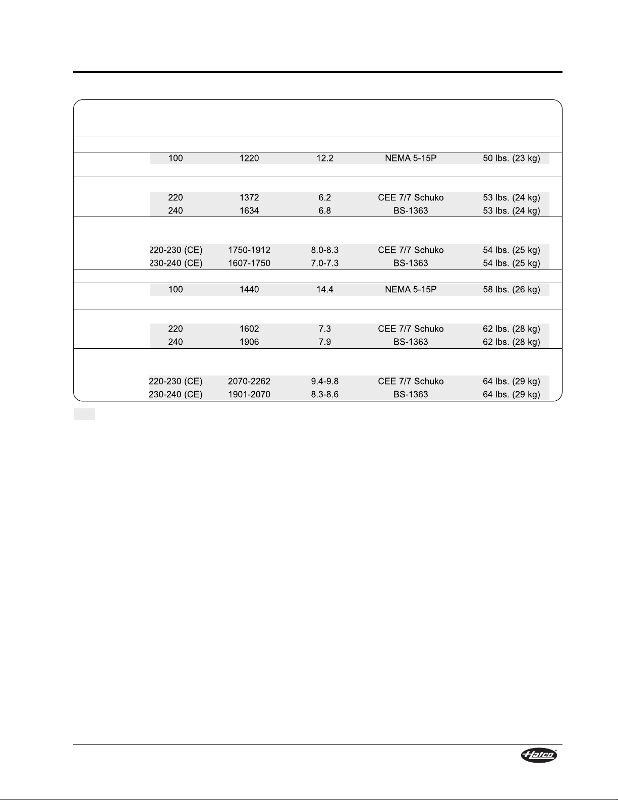
Plug Shipping
Model Voltage Watts Amps Configuration Weight
GRSBF-60-F 120 950 7.9 NEMA 5-15P 45 lbs. (20 kg)
GRSBF-60-I 100 1220 12.2 NEMA 5-15P 50 lbs. (23 kg)
120 1220 10.2 NEMA 5-15P 50 lbs. (23 kg)
GRSBF-60-S 120 1500 12.5 NEMA 5-20P 53 lbs. (24 kg)
220 1372 6.2 CEE 7/7 Schuko 53 lbs. (24 kg)
240 1634 6.8 BS-1363 53 lbs. (24 kg)
GRSBF-60-O 120 1750 14.6 NEMA 5-20P 54 lbs. (25 kg)
240 1750 7.3 NEMA 6-15P 54 lbs. (25 kg)
220-230 (CE) 1750-1912 8.0-8.3 CEE 7/7 Schuko 54 lbs. (25 kg)
230-240 (CE) 1607-1750 7.0-7.3 BS-1363 54 lbs. (25 kg)
GRSBF-72-F 120 1130 9.4 NEMA 5-15P 52 lbs. (24 kg)
GRSBF-72-I 100 1440 14.4 NEMA 5-15P 58 lbs. (26 kg)
120 1440 12.0 NEMA 5-15P 58 lbs. (26 kg)
GRSBF-72-S 120 1750 14.6 NEMA 5-20P 62 lbs. (28 kg)
220 1602 7.3 CEE 7/7 Schuko 62 lbs. (28 kg)
240 1906 7.9 BS-1363 62 lbs. (28 kg)
GRSBF-72-O 208 2070 10.0 NEMA 6-15P 64 lbs. (29 kg)
240 2070 8.6 NEMA 6-15P 64 lbs. (29 kg)
220-230 (CE) 2070-2262 9.4-9.8 CEE 7/7 Schuko 64 lbs. (29 kg)
230-240 (CE) 1901-2070 8.3-8.6 BS-1363 64 lbs. (29 kg)
SPECIFICATIONS
Form No. GRSM-0108
9
Electrical Rating Chart — Standard GRSBF Models
The shaded areas contain electrical information for Export models only.
Page 12
MODEL DESCRIPTIONS
10
Form No. GRSM-0108
MODEL DESIGNATION
GRS Model
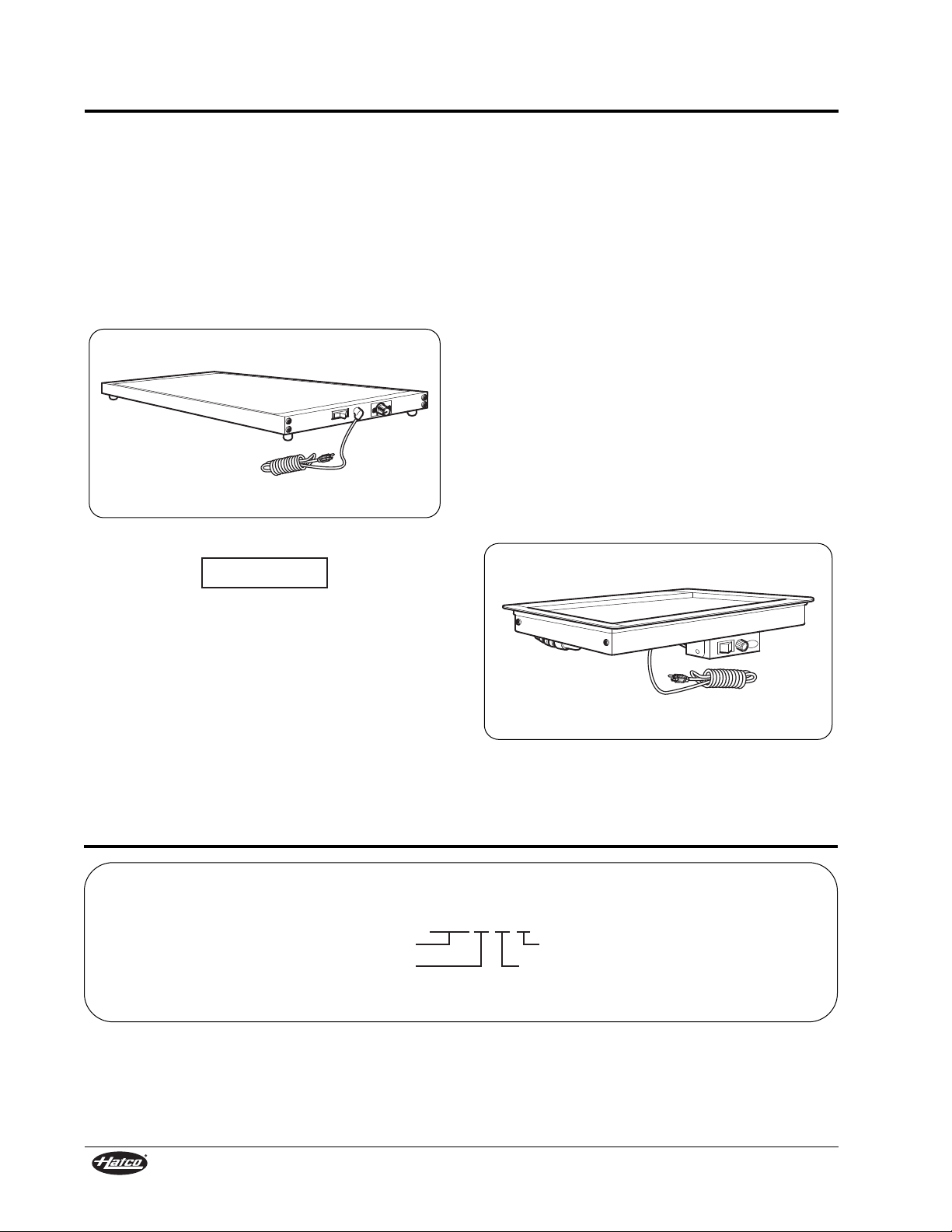
The GRS Heated Shelf is ideal for pass-through
areas, buffet lines, or as a heated work shelf. It
features an ON/OFF rocker switch with indicator
light, 140° to 180°F (60° to 82°C) adjustable
thermostat, and 6′ (1829 mm) power cord with plug.
Surface mounted foil elements distribute heat under
the entire stainless steel surface.
All GRS models are shipped from the factory
completely assembled and ready for use.
Figure 5. GRS Model
Use non-abrasive cleaners only. Abrasive
cleaners could scratch the finish of the unit,
marring its appearance and making it
susceptible to soil accumulation.
NOTICE
GRSB and GRSBF Models
The GRSB and GRSBF Built-In Heated Shelves
have a hardcoat aluminum top and a blanket-type
foil element for uniform heat distribution. Ideal for
server-to-customer pass-through areas, buffet/
cafeteria lines, and other self-service areas. The
GRSB model features a recessed top. The GRSBF
model features a flat top.
A 3′ (914 mm) flexible conduit channels the power
lines from the shelf to a remote control box. The
control box comes with a control thermostat with a
range of 80° to 200°F (27° to 93°C), an illuminated
ON/OFF switch, and mounting brackets. The
attached control box can be located up to 3′ (914
mm) from the unit. A 6′ (1829 mm) cord and plug is
attached to the control box.
The Built-In Heated Shelf has a 3/4″ (19 mm)
flanged edge that allows the unit to drop into a
countertop opening. The shelf is easy to clean with
a soft damp cloth or non-abrasive cleaner. All GRSB
and GRSBF models are shipped from the factory
completely assembled and ready for use.
Figure 6. GRSB Model
G R S B F
Glo-Ray
Heated Shelf
Built-In
Flat Top
Figure 7. Model Designation
Page 13
General
Use the following procedures to install the GRS,
GRSB, and GRSBF units.
FIRE HAZARD: Locate the unit a minimum of 1″
(25 mm) from combustible walls and materials. If
safe distances are not maintained, combustion
or discoloration could occur.
Locate the unit at the proper counter height in
an area that is convenient for use. The location
should be level to prevent the unit or its
contents from falling accidentally and strong
enough to support the weight of the unit and
contents.
The National Sanitation Foundation (NSF)
requires that heated shelf units over 36″
(914 mm) in length or weighing more than
80 lbs. (36 kg) either be sealed to or raised
above the installation surface. If this unit cannot
be sealed at the point of use, 4″ (102 mm) legs
are included to allow for proper cleaning access
below unit. Refer to the ACCESSORIES section
for installation instructions.
GRS Models
1. Remove the unit from the carton and place it
upside down on the cardboard.
2. Install the four feet into the corner holes on the
base. Tighten securely, but do not over-tighten.
NOTE: If 4″ (102 mm) legs are required, refer to the
ACCESSORIES section in this manual for
installation instructions.
3. Place one rubber boot over each metal foot.
(for 1″ [25 mm] feet only.)
4. Turn unit upright, and place unit in the desired
location. Make sure all the feet on the bottom of
the unit are positioned securely on the
countertop.
CAUTION
WARNING
INSTALLATION
Form No. GRSM-0108
11
GRSB and GRSBF Models
1. Remove the unit from the carton and place it
upside down on the cardboard.
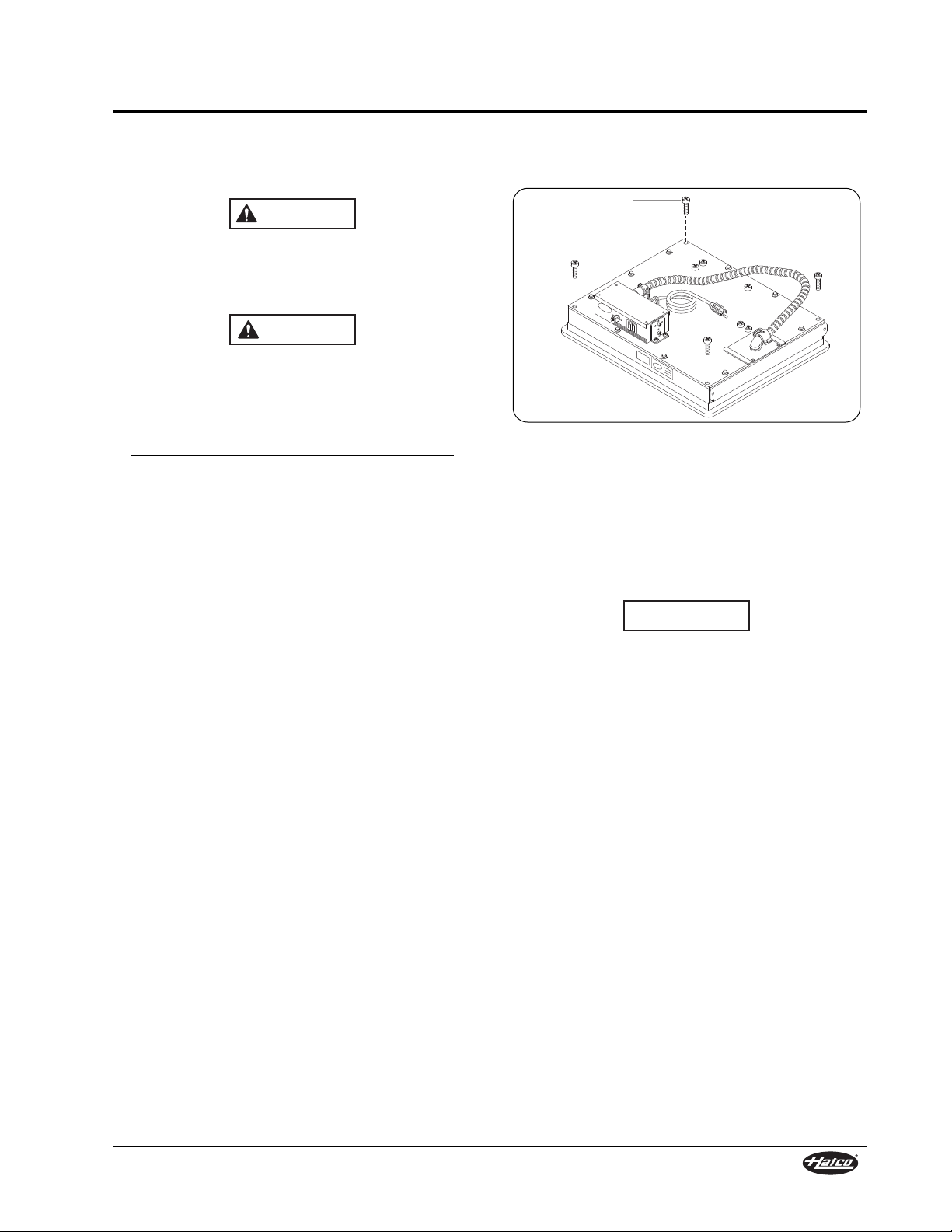
Figure 8. Models GRSB and GRSBF Underside
2. Remove and save the four bracket screws from
the underside of the unit (see Figure 8).
NOTE: The control box may be moved to the most
convenient location on the underside of the
unit. For semi-remote installations, leave
the control box in place until the unit is
placed into the countertop (see Figure 11).
This unit is recommended for use in metallic
countertops. Damage to non-metallic countertop
material caused by heat generated from Hatco
equipment is not covered under the Hatco
warranty. For other surfaces, verify that the
material is suitable for temperatures up to 200° F
(93° C)
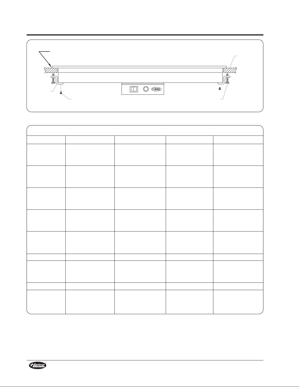
3. Prepare countertop opening. Refer to the
“Countertop Cutout” charts on the following
pages for recommended countertop cutout
dimensions.
4. Apply a bead of NSF-approved sealant between
the countertop material and the mounting flange
on the unit. The sealant must be rated for use at
a minimum temperature of 250° F (121° C).
5. Place the unit into the countertop opening.
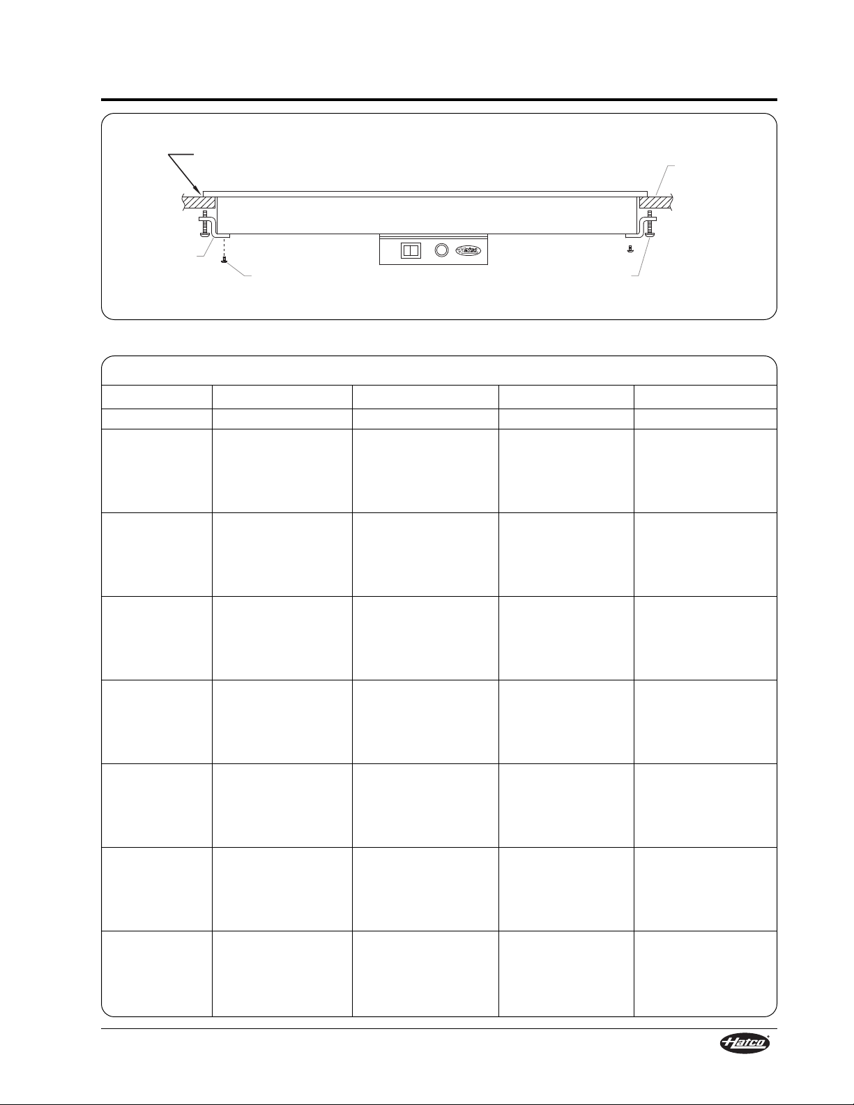
6. Assemble the Z-brackets to the underside of the
unit using the four bracket screws removed
earlier in this procedure (see Figures 9 and 10).
NOTE: Units 48″ (1219 mm) or longer require two
additional Z-brackets to be installed midway
along the front and rear of the unit.
(continued on page 14)
NOTICE
Bracket Screw
Page 14
INSTALLATION
12
Form No. GRSM-0108
Countertop Cutout
Model Minimum Width Maximum Width Minimum Depth Maximum Depth
GRSB-24-F 24-1/2″ (622 mm) 24-3/4″ (629 mm) 16″ (406 mm) 16-1/4″ (413 mm)
GRSB-24-I 24-1/2″ (622 mm) 24-3/4″ (629 mm) 20″ (508 mm) 20-1/4″ (514 mm)
GRSB-24-O 24-1/2″ (622 mm) 24-3/4″ (629 mm) 30-1/2″ (775 mm) 30-3/4″ (781 mm)
GRSB-30-F 30-1/2″ (775 mm) 30-3/4″ (781 mm) 16″ (406 mm) 16-1/4″ (413 mm)
GRSB-30-I 30-1/2″ (775 mm) 30-3/4″ (781 mm) 20″ (508 mm) 20-1/4″ (514 mm)
GRSB-30-O 30-1/2″ (775 mm) 30-3/4″ (781 mm) 30-1/2″ (775 mm) 30-3/4″ (781 mm)
GRSB-36-F 36-1/2″ (927 mm) 36-3/4″ (934 mm) 16″ (406 mm) 16-1/4″ (413 mm)
GRSB-36-I 36-1/2″ (927 mm) 36-3/4″ (934 mm) 20″ (508 mm) 20-1/4″ (514 mm)
GRSB-36-O 36-1/2″ (927 mm) 36-3/4″ (934 mm) 30-1/2″ (775 mm) 30-3/4″ (781 mm)
GRSB-42-F 42-1/2″ (1080 mm) 42-3/4″ (1086 mm) 16″ (406 mm) 16-1/4″ (413 mm)
GRSB-42-I 42-1/2″ (1080 mm) 42-3/4″ (1086 mm) 20″ (508 mm) 20-1/4″ (514 mm)
GRSB-42-O 42-1/2″ (1080 mm) 42-3/4″ (1086 mm) 30-1/2″ (775 mm) 30-3/4″ (781 mm)
GRSB-48-F 48-1/2″ (1232 mm) 48-3/4″ (1238 mm) 16″ (406 mm) 16-1/4″ (413 mm)
GRSB-48-I 48-1/2″ (1232 mm) 48-3/4″ (1238 mm) 20″ (508 mm) 20-1/4″ (514 mm)
GRSB-48-O 48-1/2″ (1232 mm) 48-3/4″ (1238 mm) 30-1/2″ (775 mm) 30-3/4″ (781 mm)
GRSB-54-I 54-1/2″ (1384 mm) 54-3/4″ (1391 mm) 20″ (508 mm) 20-1/4″ (514 mm)
GRSB-60-F 60-1/2″ (1537 mm) 60-3/4″ (1543 mm) 16″ (406 mm) 16-1/4″ (413 mm)
GRSB-60-I 60-1/2″ (1537 mm) 60-3/4″ (1543 mm) 20″ (508 mm) 20-1/4″ (514 mm)
GRSB-60-O 60-1/2″ (1537 mm) 60-3/4″ (1543 mm) 30-1/2″ (775 mm) 30-3/4″ (781 mm)
GRSB-66-I 66-1/2″ (1689 mm) 66-3/4″ (1696 mm) 20″ (508 mm) 20-1/4″ (514 mm)
GRSB-72-F 72-1/2″ (1842 mm) 72-3/4″ (1848 mm) 16″ (406 mm) 16-1/4″ (413 mm)
GRSB-72-I 72-1/2″ (1842 mm) 72-3/4″ (1848 mm) 20″ (508 mm) 20-1/4″ (514 mm)
GRSB-72-O 72-1/2″ (1842 mm) 72-3/4″ (1848 mm) 30-1/2″ (775 mm) 30-3/4″ (781 mm)
Bracket Screw
Countertop
Mounting Screw
Z-Bracket
Apply a bead of NSF-approved sealant between the
countertop and the mounting flange on the unit. Sealant
must be rated for use at a minimum temperature of 250° F (121° C).
Figure 9. GRSB Countertop Installation
Page 15
INSTALLATION
Form No. GRSM-0108
13
Countertop Cutout
Model Minimum Width Maximum Width Minimum Depth Maximum Depth
GRSBF-18-F 18-1/2″ (470 mm) 18-3/4″ (476 mm) 16″ (406 mm) 16-1/4″ (413 mm)
GRSBF-24-F 24-1/2″ (622 mm) 24-3/4″ (629 mm) 16″ (406 mm) 16-1/4″ (413 mm)
GRSBF-24-I 24-1/2″ (622 mm) 24-3/4″ (629 mm) 20″ (508 mm) 20-1/4″ (514 mm)
GRSBF-24-S 24-1/2″ (622 mm) 24-3/4″ (629 mm) 24-1/2″ (622 mm) 24-3/4″ (629 mm)
GRSBF-24-O 24-1/2″ (622 mm) 24-3/4″ (629 mm) 30-1/2″ (775 mm) 30-3/4″ (781 mm)
GRSBF-30-F 30-1/2″ (775 mm) 30-3/4″ (781 mm) 16″ (406 mm) 16-1/4″ (413 mm)
GRSBF-30-I 30-1/2″ (775 mm) 30-3/4″ (781 mm) 20″ (508 mm) 20-1/4″ (514 mm)
GRSBF-30-S 30-1/2″ (775 mm) 30-3/4″ (781 mm) 24-1/2″ (622 mm) 24-3/4″ (629 mm)
GRSBF-30-O 30-1/2″ (775 mm) 30-3/4″ (781 mm) 30-1/2″ (775 mm) 30-3/4″ (781 mm)
GRSBF-36-F 36-1/2″ (927 mm) 36-3/4″ (934 mm) 16″ (406 mm) 16-1/4″ (413 mm)
GRSBF-36-I 36-1/2″ (927 mm) 36-3/4″ (934 mm) 20″ (508 mm) 20-1/4″ (514 mm)
GRSBF-36-S 36-1/2″ (927 mm) 36-3/4″ (934 mm) 24-1/2″ (622 mm) 24-3/4″ (629 mm)
GRSBF-36-O 36-1/2″ (927 mm) 36-3/4″ (934 mm) 30-1/2″ (775 mm) 30-3/4″ (781 mm)
GRSBF-42-F 42-1/2″ (1080 mm) 42-3/4″ (1086 mm) 16″ (406 mm) 16-1/4″ (413 mm)
GRSBF-42-I 42-1/2″ (1080 mm) 42-3/4″ (1086 mm) 20″ (508 mm) 20-1/4″ (514 mm)
GRSBF-42-S 42-1/2″ (1080 mm) 42-3/4″ (1086 mm) 24-1/2″ (622 mm) 24-3/4″ (629 mm)
GRSBF-42-O 42-1/2″ (1080 mm) 42-3/4″ (1086 mm) 30-1/2″ (775 mm) 30-3/4″ (781 mm)
GRSBF-48-F 48-1/2″ (1232 mm) 48-3/4″ (1238 mm) 16″ (406 mm) 16-1/4″ (413 mm)
GRSBF-48-I 48-1/2″ (1232 mm) 48-3/4″ (1238 mm) 20″ (508 mm) 20-1/4″ (514 mm)
GRSBF-48-S 48-1/2″ (1232 mm) 48-3/4″ (1238 mm) 24-1/2″ (622 mm) 24-3/4″ (629 mm)
GRSBF-48-O 48-1/2″ (1232 mm) 48-3/4″ (1238 mm) 30-1/2″ (775 mm) 30-3/4″ (781 mm)
GRSBF-60-F 60-1/2″ (1537 mm) 60-3/4″ (1543 mm) 16″ (406 mm) 16-1/4″ (413 mm)
GRSBF-60-I 60-1/2″ (1537 mm) 60-3/4″ (1543 mm) 20″ (508 mm) 20-1/4″ (514 mm)
GRSBF-60-S 60-1/2″ (1537 mm) 60-3/4″ (1543 mm) 24-1/2″ (622 mm) 24-3/4″ (629 mm)
GRSBF-60-O 60-1/2″ (1537 mm) 60-3/4″ (1543 mm) 30-1/2″ (775 mm) 30-3/4″ (781 mm)
GRSBF-72-F 72-1/2″ (1842 mm) 72-3/4″ (1848 mm) 16″ (406 mm) 16-1/4″ (413 mm)
GRSBF-72-I 72-1/2″ (1842 mm) 72-3/4″ (1848 mm) 20″ (508 mm) 20-1/4″ (514 mm)
GRSBF-72-S 72-1/2″ (1842 mm) 72-3/4″ (1848 mm) 24-1/2″ (622 mm) 24-3/4″ (629 mm)
GRSBF-72-O 72-1/2″ (1842 mm) 72-3/4″ (1848 mm) 30-1/2″ (775 mm) 30-3/4″ (781 mm)
Countertop
Mounting Screw
Z-Bracket
Apply a bead of NSF-approved sealant between the
countertop and the mounting flange on the unit. Sealant
must be rated for use at a minimum temperature of 250° F (121° C).
Bracket Screw
Figure 10. GRSBF Countertop Installation
Page 16
INSTALLATION
14
Form No. GRSM-0108
7. Adjust the mounting screws on the Z-brackets
until the top flange lies flat on the countertop.
Use of excessive force when tightening
mounting screws of built-in units may damage
unit or countertop.
8. Remove any excess sealant.
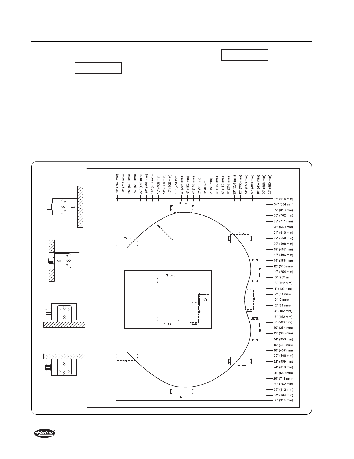
9. If you wish to move the control box to a semiremote location, remove it from the bottom of
the unit. If necessary, remove the end brackets
from the control box, rotate and reposition them.
The control box will require a hole mounting
pattern of 7-5/8″ x 1-1/4″ (194 mm x 32 mm) for
#8 screws. See Figure 11 for mounting
distances.
NOTICE
Do not modify wiring or cut thermostat capillary
wire on control box to increase semi-remote
mounting distance. Cutting the thermostat
capillary wire will cause the unit to overheat and
may damage the unit as well as the surrounding
countertop.
10. Once all components are secured, proceed to
the OPERATION section.
NOTE: A 6′ (1829 mm) cord is supplied with this
unit; any excess cord should be neatly
routed so it does not hang down.
NOTICE
Use this arc to determine
approximate mounting
distances for semi-remote
controls.
Top View
Under Counter
Surface
Recessed
Panel
Optional
Standard
Optional
Figure 11. Maximum Semi-Remote Mounting Distance for Control Box
Page 17
OPERATION
Form No. GRSM-0108
15
General
Use the following procedure to turn on and operate
the GRS, GRSB, and GRSBF units.
Read all safety messages in the IMPORTANT
SAFETY INFORMATION section before
operating this equipment.
1. Plug unit into a properly grounded electrical
outlet of the correct voltage, size, and plug
configuration. Refer to the SPECIFICATIONS
section in this manual for details.
2. Move the power ON/OFF switch to the ON
position.
BURN HAZARD: Some exterior surfaces on the
unit will get hot. Use caution when touching
these areas.
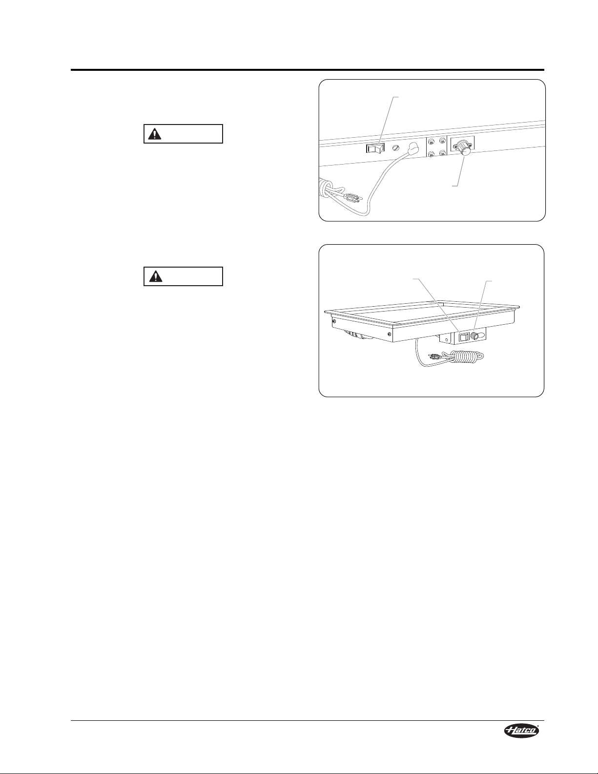
3. Turn the thermostat control to the desired
temperature setting.
4. Allow the unit 30 minutes to reach operating
temperature.
NOTE: Refer to the ACCESSORIES section for
installation and operation information for
GRSB and GRSBF units equipped with a
flush-style remote mounted control panel.
WARNING
CAUTION
Thermostat
Control
Power ON/OFF
Switch
Figure 12. Operating Controls — GRS
Power ON/OFF
Switch
Thermostat
Control
Figure 13. Operating Controls —
GRSB (shown) and GRSBF
Page 18
MAINTENANCE
16
Form No. GRSM-0108
General
The Hatco Glo-Ray Heated Shelf units are designed
for maximum durability and performance with
minimum maintenance.
ELECTRIC SHOCK HAZARD:
• Turn the power switch OFF, unplug the power
cord, and allow the unit to cool before
performing any maintenance or cleaning.
• DO NOT submerge or saturate with water.
Unit is not waterproof. Do not operate if unit
has been submerged or saturated with water.
Cleaning
To preserve the finish of the Glo-Ray Heated Shelf,
it is recommended that the surfaces be wiped daily
with a damp cloth. Stubborn stains may be removed
with a good stainless steel cleaner or a nonabrasive cleaner. Hard to reach areas should be
cleaned with a small brush and mild soap.
Use non-abrasive cleaners only. Abrasive
cleaners could scratch the finish of the unit,
marring its appearance and making it
susceptible to soil accumulation.
WARNING
NOTICE
This unit has no “user-serviceable” parts. If
service is required on this unit, contact an
Authorized Hatco Service Agent or contact the
Hatco Service Department at 800-558-0607 or
414-671-6350; fax 800-690-2966; or International
fax 414-671-3976.
Use only Genuine Hatco Replacement Parts
when service is required. Failure to use Genuine
Hatco Replacement Parts may subject operators
of the equipment to hazardous electrical
voltage, resulting in electrical shock or burn.
Genuine Hatco Replacement Parts are specified
to operate safely in the environments in which
they are used. Some aftermarket or generic
replacement parts do not have the
characteristics that will allow them to operate
safely in Hatco equipment.
WARNING
Page 19
TROUBLESHOOTING GUIDE
Form No. GRSM-0108
17
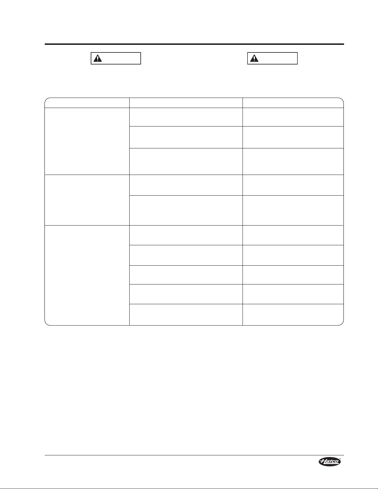
Unit too hot.
Unit not hot enough.
Unit not working at all.
Thermostat control set too high.
Thermostat control stuck in the ON
position.
Unit plugged into an incorrect power
supply.
Thermostat control set too low.
Location of unit is susceptible to air
currents (air conditioning ducts or
exhaust fans).
Unit not plugged in.
Unit not turned on.
Power ON/OFF switch is not
functioning.
Heating element is burned out.
Thermostat control is defective.
Place power ON/OFF switch in
the ON position.
Contact Authorized Service Agent
or Hatco for assistance.
Contact Authorized Service Agent
or Hatco for assistance.
Contact Authorized Service Agent
or Hatco for assistance.
Plug unit into proper power
supply.
Adjust thermostat control to a
higher setting.
Block air currents or relocate unit.
Adjust thermostat control to a
lower setting.
Contact Authorized Service Agent
or Hatco for assistance.
Verify with qualified personnel
that power supply matches unit
specification.
Symptom Probable Cause Corrective Action
This unit must be serviced by qualified
personnel only. Service by unqualified
personnel may lead to electric shock or burn.
WARNING
ELECTRIC SHOCK HAZARD: Turn the power
switch OFF, unplug the power cord, and allow
the unit to cool before performing any
maintenance or cleaning.
WARNING
Page 20
ACCESSORIES
18
Form No. GRSM-0108
4″ Adjustable Legs (GRS Models)
NOTE: 4″ (102 mm) legs are standard on models
42″ (1067 mm) and wider.
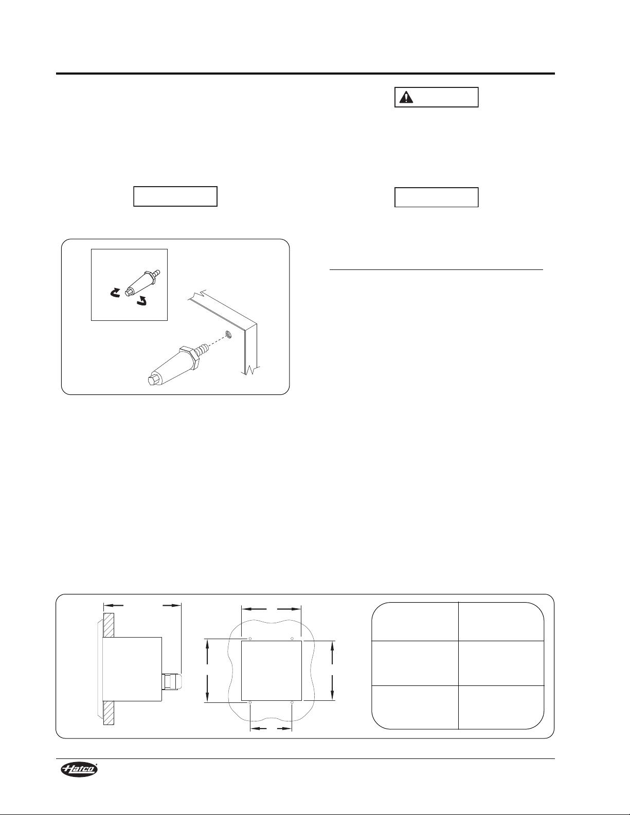
Carefully lay unit on its side. Install legs to bottom of
unit (see Figure 14). Hand-tighten legs until snug.
Do not over-tighten. Return unit to the upright
position.
Do not lay unit on the side with the control panel
or damage to unit could occur.
Figure 14. Leg Installation
NOTE: Legs are adjustable for leveling the unit.
Use a 9/16″ (14 mm) open-end wrench to
make leveling adjustments once the unit is
placed in final position.
Remote Mounted Control Panels
(GRSB and GRSBF models)
Two flush-style remote mounted control panels are
available for the GRSB and GRSBF units — the
mechanical Thermostat Control panel and the digital
Indicating Temperature Control (ITC) panel. Both
control panels are installed using the following
procedure.
NOTICE
Lengthen
Shorten
Leg Adjustment
ELECTRIC SHOCK HAZARD: The remote
mounted control panel must be mounted on a
vertical wall and installed in the vertical
position. Mounting the control panel in the
horizontal position may result in the collection
of liquids and lead to an electric shock.
The remote mounted control panel should be
installed outside of the heat zone. Locating the
control panel inside the heat zone will cause the
control(s) to overheat, malfunction, and fail. See
Figure 11 for maximum mounting distances.
Do not modify wiring or cut thermostat capillary
wire on control box to increase semi-remote
mounting distance. Cutting the thermostat
capillary wire will cause the unit to overheat and
may damage the unit as well as the surrounding
countertop.
NOTE: A qualified electrician is recommended for
connecting the units to a power source.
1. Prepare cutout and pre-drill screw holes (see
Figure 15).
2. Remove trim cover from control panel
assembly.
3. Position control panel into opening through the
backside.
4. Secure control panel to surface using screws
(not supplied).
5. Connect proper power source to the mounted
remote control panel.
6. Reinstall trim cover.
NOTE: Units are equipped with a 36″
(914 mm) flexible conduit connecting the
control panel to the unit.
WARNING
NOTICE
Figure 15. Remote Mounted Control Panel Installation Dimensions
4-3/4″
(121 mm)
A
D B
C
Cutout Screw Hole
Dimension Dimension
(A) (C)
5-7/8″ 3-7/8″
(149 mm) (98 mm)
(B) (D)
6-3/8″ 6-3/4″
(162 mm) (171 mm)
Page 21
ACCESSORIES
Form No. GRSM-0108
19
Power ON/OFF Switch
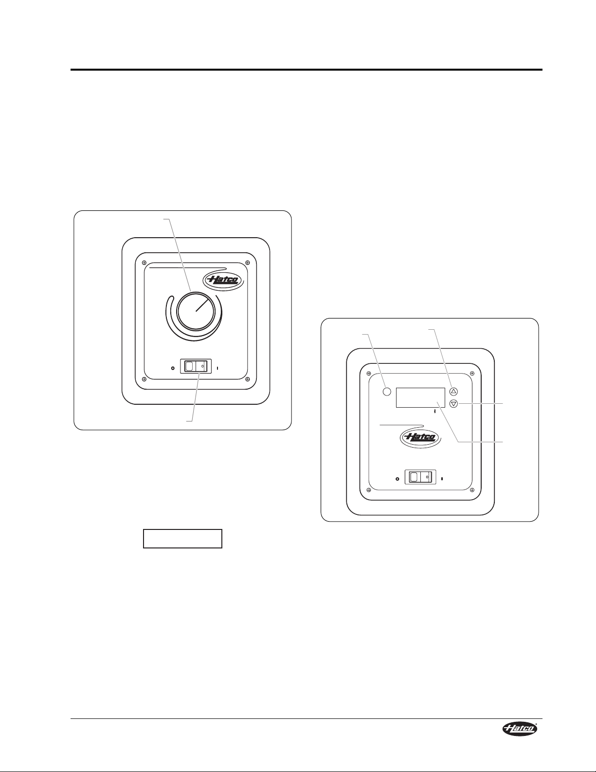
Both fllush-style remote mounted control panels are
equipped with a power ON/OFF switch. Move the
power ON/OFF switch to the ON position to turn on
the unit. The indicator light in the switch glows when
the unit is on (see Figure 16).
Adjusting the Thermostat Control Panel
Turn the thermostat control clockwise to increase
the temperature setpoint. Turn the thermostat
control counterclockwise to decrease the
temperature setpoint.
Figure 16. Thermostat Control Panel
Adjusting/Programming the ITC Panel
Units equipped with the ITC panel will heat up to the
setpoint temperature automatically when they are
turned on. Use the following procedure to program
the setpoint temperature.
Built-in units must not have a setpoint
temperature higher than 200°F (93°C).
Temperatures exceeding 200°F (93°C) will
damage the unit and void the warranty.
NOTE: The temperature shown on the display may
be inaccurate when unit temperature is
below 130°F (54°C).
If the programming sequence is interrupted before
completing the last step, the changed values will not
be accepted into memory.
NOTICE
HATCO CORP. MILWAUKEE, WI U.S.A.
OFF ON
1
2
3
4
56
7
8
9
10
Thermostat
Control
Power ON/OFF Switch
1. Press the SET key once to view temperature
setpoint (SP) on the display.
2. Press the SET key again to view the current
setpoint value.
3. Press the Up or Down arrow key to select the
desired setpoint value. Pressing and holding
either of the arrow keys will advance the
setpoint change rapidly.
4. Press the SET key to complete the
programming sequence and enter the value into
memory. The display will go blank for two
seconds to acknowledge the end of the
programming sequence and acceptance of the
new temperature value.
NOTE: After ten seconds of inactivity during the
programming process, the controller will
automatically exit programming mode and
revert back to the original temperature
value without accepting the new value.
Figure 17. Indicating Temperature Control (ITC) Panel
HATCO CORP. MILWAUKEE, WI U.S.A.
OFF ON
SET
TEMPERATURE
SET Key
Up Arrow
Key
Down
Arrow
Key
Display
Page 22

HATCO LIMITED WARRANTY
Form No. GRSM-0108
21
1. PRODUCT WARRANTY
Hatco warrants the products that it manufactures
(the “Products”) to be free from defects in materials
and workmanship, under normal use and service,
for a period of one (1) year from the date of
purchase when installed and maintained in
accordance with Hatco’s written instructions or 18
months from the date of shipment from Hatco. Buyer
must establish the product’s purchase date by
returning Hatco’s Warranty Registration Card or by
other means satisfactory to Hatco in its sole
discretion.
Hatco warrants the following Product components to
be free from defects in materials and workmanship
from the date of purchase (subject to the foregoing
conditions) for the period(s) of time and on the
conditions listed below:
a) One (1) Year Parts and Labor PLUS One
(1) Additional Year Parts-Only Warranty:
Toaster Elements (metal sheathed)
Drawer Warmer Elements (metal sheathed)
Drawer Warmer Drawer Rollers and Slides
Food Warmer Elements (metal sheathed)
Display Warmer Elements (metal sheathed air
heating)
Holding Cabinet Elements (metal sheathed air
heating)
Built-In Heated Well Elements
(metal sheathed)
b) One (1) Year Parts and Labor PLUS Four
(4) Years Parts-Only Warranty on
pro-rated terms that Hatco will explain
at Buyer’s request:
3CS and FR Tanks
c) One (1) Year Parts and Labor PLUS Nine
(9) Years Parts-Only Warranty on:
Electric Booster Heater Tanks
Gas Booster Heater Tanks
THE FOREGOING WARRANTIES ARE
EXCLUSIVE AND IN LIEU OF ANY OTHER
WARRANTY, EXPRESSED OR IMPLIED,
INCLUDING BUT NOT LIMITED TO ANY IMPLIED
WARRANTY OF MERCHANTABILITY OR
FITNESS FOR A PARTICULAR PURPOSE OR
PATENT OR OTHER INTELLECTUAL PROPERTY
RIGHT INFRINGEMENT. Without limiting the
generality of the foregoing, SUCH WARRANTIES
DO NOT COVER: Coated incandescent light bulbs,
fluorescent lights, lamp warmer heat bulbs, glass
components, Product failure in booster tank, fin tube
heat exchanger, or other water heating equipment,
caused by liming, sediment buildup, chemical attack
or freezing, Product misuse, tampering or
misapplication, improper installation or application of
improper voltage.
2. LIMITATION OF REMEDIES AND DAMAGES
Hatco’s liability and Buyer’s exclusive remedy
hereunder will be limited solely, at Hatco’s option, to
repair or replacement by a Hatco-authorized service
agency (other than where Buyer is located outside
of the United States, Canada, United Kingdom or
Australia in which case Hatco’s liability and Buyer’s
exclusive remedy hereunder will be limited solely to
replacement of part under warranty) with respect to
any claim made within the applicable warranty
period referred to above. Hatco reserves the right to
accept or reject any such claim in whole or in part.
Hatco will not accept the return of any Product
without prior written approval from Hatco, and all
such approved returns shall be made at Buyer’s
sole expense. HATCO WILL NOT BE LIABLE,
UNDER ANY CIRCUMSTANCES, FOR
CONSEQUENTIAL OR INCIDENTAL DAMAGES,
INCLUDING BUT NOT LIMITED TO LABOR
COSTS OR LOST PROFITS RESULTING FROM
THE USE OF OR INABILITY TO USE THE
PRODUCTS OR FROM THE PRODUCTS BEING
INCORPORATED IN OR BECOMING A
COMPONENT OF ANY OTHER PRODUCT OR
GOODS.
Page 23

HATCO CORPORATION
P.O. Box 340500
Milwaukee, WI 53234-0500 U.S.A.
(800) 558-0607 (414) 671-6350
Parts and Service Fax (800) 690-2966
International Fax (414) 671-3976
www.hatcocorp.com
Printed in U.S.A. January 2008 Part No. 07.04.288.00 Form No. GRSM-0108
HATCO AUTHORIZED PARTS DISTRIBUTORS
ALABAMA
Jones McLeod Appl. Svc.
Birmingham 205-251-0159
ARIZONA
Auth. Comm. Food Equip.
Phoenix 602-234-2443
Byassee Equipment Co.
Phoenix 602-252-0402
CALIFORNIA
Industrial Electric
Commercial Parts & Service, Inc.
Huntington Beach 714-379-7100
Chapman Appl. Service
San Diego 619-298-7106
P & D Appliance
Commercial Parts & Service, Inc.
S. San Francisco 650-635-1900
COLORADO
Hawkins Commercial Appliance
Englewood 303-781-5548
FLORIDA
Whaley Foodservice Repair
Jacksonville 904-725-7800
Nass Service Co., Inc.
Orlando 407-425-2681
B.G.S.I.
Pompano Beach 954-971-0456
Comm. Appliance Service
Tampa 813-663-0313
GEORGIA
TWC Services
Smyrna 770-438-9797
Heritage Service Group
Norcross 866-388-9837
Southeastern Rest. Svc.
Norcross 770-446-6177
HAWAII
Burney’s Comm. Service, Inc.
Honolulu 808-848-1466
Food Equip Parts & Service
Honolulu 808-847-4871
ILLINOIS
Parts Town
Lombard 708-865-7278
Eichenauer Elec. Service
Decatur 217-429-4229
Midwest Elec. Appl. Service
Elmhurst 630-279-8000
Cone’s Repair Service
Moline 309-797-5323
INDIANA
GCS Service
Indianapolis 317-545-9655
IOWA
Electric Motor Service Co.
Davenport 319-323-1823
Goodwin Tucker Group
Des Moines 515-262-9308
KENTUCKY
Certified Service Center
Lexington 859-254-8854
Certified Service Center
Louisville 502-964-7007
LOUISIANA
Chandlers Parts & Service
Baton Rouge 225-272-6620
MARYLAND
Electric Motor Service
Baltimore 410-467-8080
GCS Service
Silver Spring 301-585-7550
MASSACHUSETTS
Ace Service Co., Inc.
Needham 781-449-4220
MICHIGAN
Commercial Kitchen Service
Bay City 517-893-4561
Bildons Appliance Service
Detroit 248-478-3320
Midwest Food Equip. Service
Grandville 616-261-2000
MINNESOTA
GCS Service
Minneapolis 612-546-4221
MISSOURI
General Parts
Kansas City 816-421-5400
Commercial Kitchen Services
St. Louis 314-890-0700
Kaemmerlen Parts & Service
St. Louis 314-535-2222
NEBRASKA
Anderson Electric
Omaha 402-341-1414
NEVADA
Burney’s Commercial
Las Vegas 702-736-0006
Hi. Tech Commercial Service
N. Las Vegas 702-649-4616
NEW JERSEY
Jay Hill Repair
Fairfield 973-575-9145
Service Plus
Flanders 973-691-6300
NEW YORK
Acme American Repairs, Inc.
Brooklyn 718-456-6544
Alpro Service Co.
Brooklyn 718-386-2515
Appliance Installation
Buffalo 716-884-7425
Northern Parts Dist.
Plattsburgh 518-563-3200
J.B. Brady, Inc.
Syracuse 315-422-9271
NORTH CAROLINA
Authorized Appliance
Charlotte 704-377-4501
OHIO
Akron/Canton Comm. Svc. Inc.
Akron 330-753-6635
Certified Service Center
Cincinnati 513-772-6600
Commercial Parts and Service
Columbus 614-221-0057
Electrical Appl. Repair Service
Independence 216-459-8700
E. A. Wichman Co.
Toledo 419-385-9121
OKLAHOMA
Hagar Rest. Service, Inc.
Oklahoma City 405-235-2184
Krueger, Inc.
Oklahoma City 405-528-8883
OREGON
Ron’s Service, Inc.
Portland 503-624-0890
PENNSYLVANIA
Elmer Schultz Services
Philadelphia 215-627-5401
FAST Comm. Appl. Service
Philadelphia 215-288-4800
Appliance Installation & Service
Pittsburgh 412-809-0244
K & D Service Co.
Harrisburg 717-236-9039
Electric Repair Co.
Reading 610-376-5444
RHODE ISLAND
Marshall Electric Co.
Providence 401-331-1163
SOUTH CAROLINA
Whaley Foodservice Repair
W. Columbia 803-791-4420
TENNESSEE
Camp Electric
Memphis 901-527-7543
TEXAS
GCS Service
Fort Worth 817-831-0381
Armstrong Repair Service
Houston 713-666-7100
Commercial Kitchen Repair Co.
San Antonio 210-735-2811
UTAH
La Monica’s Rest. Equip. Service
Murray 801-263-3221
VIRGINIA
Daubers
Norfolk 757-855-4097
Daubers
Springfield 703-866-3600
WASHINGTON
Restaurant Appl. Service
Seattle 206-524-8200
WISCONSIN
A.S.C., Inc.
Madison 608-246-3160
A.S.C., Inc.
Milwaukee 414-543-6460
CANADA
ALBERTA
Key Food Equipment Service
Edmonton 780-438-1690
BRITISH COLUMBIA
Key Food Equipment Service
Vancouver 604-433-4484
MANITOBA
Air Rite, Inc.
Winnepeg 204-895-2300
N
EW BRUNSWICK
EMR Services, Ltd.
Moncton 506-855-4228
ONTARIO
R.G. Henderson Ltd.
Toronto 416-422-5580
Choquette CKS
Ottawa 613-739-8458
QUEBEC
Choquette CKS
Montreal 514-722-2000
Choquette CKS
Québec City 418-681-3944
 Loading...