

Page 1
GLO-RAY
CAUTION- HOT
GLO-RAY
Foodwarmer
HATCOCORP.MILWAUKEE,WI U.S.A.
ON
OFF
O
PARTS&SERVICE
ASSISTANCE
WWWHATCOCORPCOM
800-558-0607
CAUTION-HOT
GLO-RAY
Foodwarmer
HATCOCO
RPMI
LWAUKEEW
IUSA
ON
OFF
O
PAR
TS&SER
VIC
E
ASSISTANCE
WWW
HA
TCO
COR
PC
OM
800
-55
8-0607
CAUTION- HOT
GLO-RAY
Foodwarmer
HATCOCORP.MILWAUKEE,WI U.S.A.
ON
OFF
O
PARTS&SERVICE
ASSISTANCE
WWWHATCOCORPCOM
800-558-0607
®
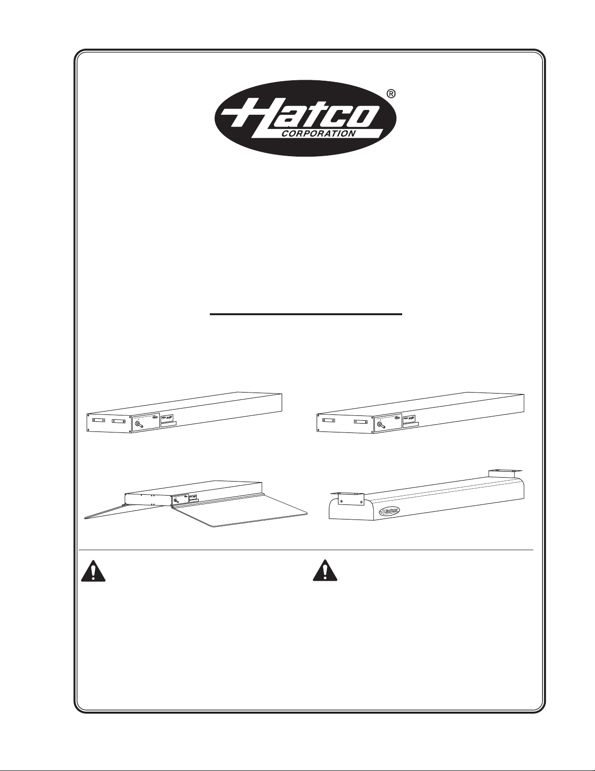
Infrared Strip Heaters
GR, GRH, GRA, GRAH, GRAL,
GRAHL, GRN, and GRNH Series
Installation and Operating Manual
I&W #07.05.183.00
Do not operate this equipment unless
you have read and understood the
contents of this manual! Failure to follow
the instructions contained in this manual
may result in serious injury or death.
This manual contains important safety
information concerning the
maintenance, use, and operation of this
product. If you’re unable to understand
the contents of this manual, please bring
it to the attention of your supervisor.
Keep this manual in a safe location for
future reference.
No opere este equipo al menos que haya
leído y comprendido el contenido de este
manual! Cualquier falla en el
seguimiento de las instrucciones
contenidas en este manual puede
resultar en un serio lesión o muerte. Este
manual contiene importante información
sobre seguridad concerniente al
mantenimiento, uso y operación de este
producto. Si usted no puede entender el
contenido de este manual por favor
pregunte a su supervisor. Almacenar
este manual en una localización segura
para la referencia futura.
© 2008 Hatco Corporation
Page 2
CONTENTS
NOTICE
CAUTION
WARNING
Important Owner Information...............................i
Introduction...........................................................i
Important Safety Information..............................1
Model Designations .............................................2
Model Descriptions..............................................3
Specifications.......................................................4
Electrical Rating Charts...................................4
Dimensions....................................................10
Installation...........................................................11
General..........................................................11
Mounting Height Requirements.....................12
Assembly.......................................................12
Portable Surface Mount ................................12
Minimum Clearance Requirements...............14
Permanent Surface Mount ............................15
Undershelf Mounting .....................................16
Ceiling Mounting ...........................................17
Electrical Wiring Hook-Up .............................18
Operation............................................................19
Maintenance .......................................................20
Cleaning........................................................20
Display Light Bulb Replacement...................20
Accessories........................................................21
Troubleshooting Guide......................................22
Hatco Limited Warranty.....................................24
Authorized Parts Distributors...........Back Cover
IMPORTANT OWNER INFORMATION
Record the model number, serial number
(identification decal located on the underside of the
unit), voltage, and purchase date of your strip heater
in the spaces below. Please have this information
available when calling Hatco for service assistance.
Model No. ________________________________
Serial No. ________________________________
Voltage __________________________________
Date of Purchase __________________________
Business 8:00 a.m. to 5:00 p.m.
Hours: Central Standard Time
Telephone: (800) 558-0607; (414) 671-6350
Fax: (800) 690-2966 (Parts and Service)
(Summer Hours: June to September –
8:00 a.m. to 5:00 p.m. C.S.T.
Monday through Thursday
8:00 a.m. to 2:30 p.m. C.S.T. Friday)
(414) 671-3976 (International)
24 Hour 7 Day Parts and Service
Assistance available in the
United States and Canada
by calling (800) 558-0607.
INTRODUCTION
Hatco Glo-Ray®Strip Heaters ensure maximum food
holding and minimize the risk of food-borne illness.
Optimum safety and quality is the result of food held
at the proper serving temperatures, using Glo-Ray’s
pre-focused heat patterns. The pre-focused heat
pattern prevents foods frombeing over-cooked in the
middle and cooling off around the edges by
concentratinghighertemperaturesto the outer edges
of holding surfaces where heat loss is the greatest.
Utilizing specially designed reflectors to direct the
heat from the element, Glo-Ray Strip Heaters safely
maintain peak serving temperatures longer without
cooking the food beyond the point of excellence.
Glo-Ray Strip Heaters are available from the factory
withor without shatter-resistantincandescentlightsto
illuminate the warming area. These bulbs have a
special coating that guards against injury and food
contamination in the event of breakage.
Glo-Ray Strip Heaters are a product of extensive
research and field testing. The materials used were
selected for maximum durability, attractive
appearance,and optimumperformance.Every unit is
inspected and tested thoroughly prior to shipment.
Additional information can be found by visiting our
web site at www.hatcocorp.com.
This manual provides the installation, safety, and
operating instructions for Glo-Ray Strip Heaters.
Hatco recommends all installation, operating, and
safety instructions appearing in this manual be read
prior to installation or operation of the Strip Heaters.
Safety information that appears in this manual is
identified by the following signal word panels:
WARNING indicates a hazardous situation
which, if not avoided, could result in death or
serious injury.
CAUTION indicates a hazardous situation which,
if not avoided, could result in minor or moderate
injury.
NOTICE is used to address practices not related
to personal injury.
i
Form No. GRM-0508
Page 3
IMPORTANT SAFETY INFORMATION
WARNING
WARNING
Read the following important safety information before using this equipment to avoid
serious injury or death and to avoid damage to equipment or property.
ELECTRIC SHOCK HAZARD:
• For hard-wired units, all electrical
connections must be in accordance with
local electrical codes and any other
applicable codes. Connections should be
made by a qualified, licensed electrician.
• Units equipped with a cord and plug supplied
by Hatco must be plugged into a properly
grounded electrical outlet of the correct
voltage, size, and plug configuration. If the
plug and receptacle do not match, contact a
qualified electrician to determine and install
the proper voltage and size electrical outlet.
• Unplug the power cord or turn the power OFF
at the fused disconnect switch/circuit
breaker and allow the unit to cool before
performing any maintenance or cleaning.
• Discontinue use if power cord is frayed or
worn.
• Do not attempt to repair or replace a
damaged power cord. The cord must be
replaced by Hatco, an Authorized Hatco
Service Agent, or a person with similar
qualifications.
• DO NOT submerge or saturate with water.
Unit is not waterproof. Do not operate if unit
has been submerged or saturated with water.
• This unit is not “jet-proof” construction. Do
not use jet-clean spray to clean this unit.
• Use only Genuine Hatco Replacement Parts
when service is required. Failure to use
Genuine Hatco Replacement Parts will void
all warranties and may subject operators of
the equipment to hazardous electrical
voltage, resulting in electrical shock or burn.
Genuine Hatco Replacement Parts are
specified to operate safely in the
environments in which they are used. Some
aftermarket or generic replacement parts do
not have the characteristics that will allow
them to operate safely in Hatco equipment.
FIRE HAZARD:
• Locate the unit the correct distance from
combustible walls and materials. If safe
distances are not maintained, discoloration
or combustion could occur. Refer to specific
installation and mounting information in this
manual for proper clearances.
• Make sure to follow the installation
information listed below for specific strip
heaters. If safe distances are not maintained,
discoloration or combustion could occur.
a. Do not install standard wattage strip
heaters (GR, GRA, GRN, GRAL Series)
less than 10″ (254 mm) above combustible
surfaces.
b. Do not install high wattage strip heaters
(GRH, GRAH, GRNH, GRAHL Series) less
than 13-1/2″ (343 mm) above combustible
surfaces.
c. Do not install dual strip heaters (GRA-
XXD, GRAH-XXD, GRAL-XXD, and GRAHLXXD Series) above combustible surfaces.
e. Install all single strip heaters with a
minimum distance of 3″ (76 mm) from a
combustible wall or adjacent surface.
• Do not store or use gasoline or other
flammable vapors or liquids in the vicinity of
this or any other appliance.
Use only light bulbs that meet or exceed
(National Sanitation Foundation (NSF)
standards and are specifically designed for food
holding areas. Breakage of light bulbs not
specially coated could result in personal injury
and/or food contamination.
For installation with chains, make sure the
chains have sufficient strength and are securely
fastened to both the unit and the mounting
location. Poorly installed chains may cause the
unit to loosen and fall. Do not place anything on
top of units installed with chains.
Form No. GRM-0508
This unit has no “user-serviceable” parts. If
service is required on this unit, contact an
Authorized Hatco Service Agent or contact the
Hatco Service Department at 800-558-0607 or
414-671-6350; fax 800-690-2966; or International
fax 414-671-3976.
1
Page 4
IMPORTANT SAFETY INFORMATION
CAUTION
NOTICE
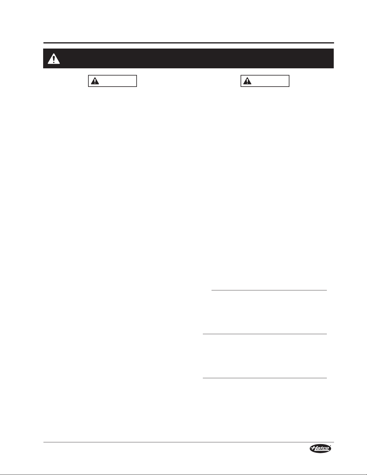
G R A H L - 24 D
Glo-Ray
Housing Type
A = Aluminum
N = Narrow Powder-Coated Steel
No Character = Stainless Steel Housing
Incandescent Light
Dual Elements
Width (in inches)
High Wattage
BURN HAZARD: Some exterior surfaces on the
unit will get hot. Use caution when touching
these areas.
Standard and approved manufacturing oils may
smoke up to 30 minutes during initial startup.
This is a temporary condition. Operate unit
without food product until smoke dissipates.
Strip heaters equipped with incandescent lights
that require a circuit breaker larger than 20 amps
for the heat element must have a separate circuit
breaker for the incandescent lights that is 20
amps or less.
To ensure safe and proper operation, refer to the
Clearance Requirements listed in the Installation
section of this manual.
Installation of two or more separate units with
less than 3″ (76 mm) between housings may
result in premature failure of component parts.
Failure to provide proper spacing may result in
heat damage to electrical components.
To prevent unit failure, do not add a decorative
soffit to hide a pass-through mounted strip
heater.
To prevent premature failure of components due
to excessive heat, remote mounted control
boxes must be installed outside the strip heater
heat zone.
Heat damage to countertop material such as
Corian®and similar products (other than
stainless steel) is not covered under the Hatco
warranty. Contact the manufacturer of the base
material for temperature limits and application
information before installing the unit.
Use non-abrasive cleaners only. Abrasive
cleaners could scratch the finish of the unit,
marring its appearance and making it
susceptible to dirt accumulation.
MODEL DESIGNATION
Figure 1. Model Designation
2
Form No. GRM-0508
Page 5
Hatco Glo-Ray®Infrared Strip Heaters keep hot
CAUTION- HOT
GLO-RAY
Foodwarmer
HATCOCORP.MILWAUKEE,WI U.S.A.
ON
OFF
O
PARTS&SERVICE
ASSISTANCE
WWWHATCOCORPCOM
800-558-0607
CAUTION- HOT
GLO-RAY
Foodwarmer
HATCOCORP.MILWAUKEE,WI U.S.A.
ON
OFF
O
PARTS&SERVICE
ASSISTANCE
WWWHATCOCORPCOM
800-558-0607
CAUTION- HOT
GLO-RAY
Foodwarmer
HATCOCORP.MILWAUKEE,WI U.S.A.
ON
OFF
O
PARTS&SERVICE
ASSISTANCE
WWWHATCOCORPCOM
800-558-0607
foods at optimum serving temperatures longer.
Foods do not dry out or become discolored; even
the most delicate dishes hold that “just-prepared”
look. The Glo-Ray pre-focused heat pattern directs
heat from a tubular element to bathe the entire
holding surface.
Glo-Ray strip heaters can be ordered in standard or
high wattage configurations, aluminum housings in
lengths of 18″ (457 mm) to 144″ (3658 mm),
stainless steel housings in lengths of 24″ (610 mm)
to 96″ (2438 mm), or narrow design housings in
lengths of 18″ (457 mm) to 72″ (1829 mm).
Glo-Ray dual models allow for side-by-side
mounting of two or more strip heaters to provide a
wider holding area (dual models are constructed
with a required 3″ [76 mm] or 6″ [152 mm] spacer
between heating elements).
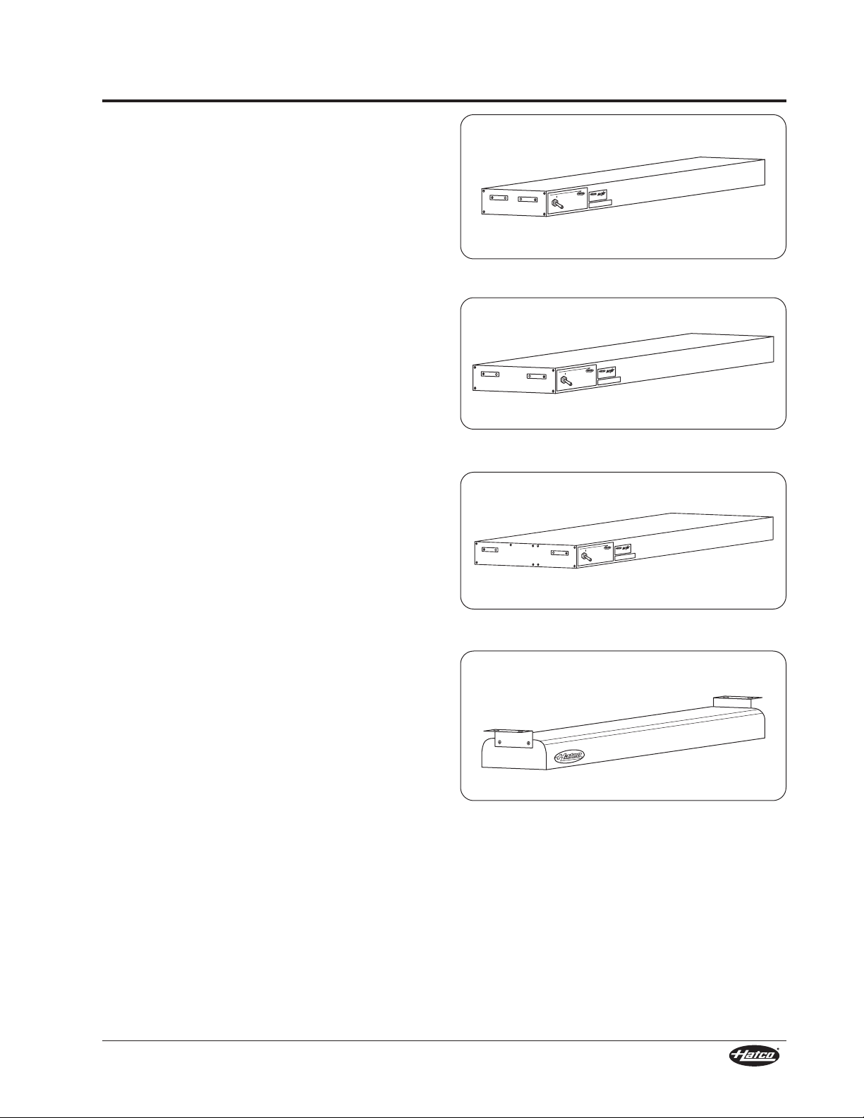
MODEL DESCRIPTIONS
Figure 2. GRA-24 Model
All strip heaters have several mounting options and
switch locations. Optional infinite control switches,
remote control enclosures, incandescent lighting,
and sneeze guards are available.
GR-XX: Stainless steel housing,
standard wattage
GRH-XX: Stainless steel housing, high wattage
GRN-XX: Narrow design, powder-coated
steel housing, standard wattage
GRNH-XX: Narrow design, powder-coated
steel housing, high wattage
NOTE: Stainless steel and narrow design strip
heaters are not available with lights, sneeze
guards, or as dual units.
GRA-XX: Aluminum housing, standard wattage
GRAH-XX: Aluminum housing, high wattage
GRAL-XX: Aluminum housing, standardwattage,
incandescent light
GRAHL-XX: Aluminum housing, high wattage,
incandescent light
GRA-XXD: Aluminum housing, standard wattage,
dual
Figure 3. GRAHL-24 Model
Figure 4. GRA-24D Model
Figure 5. GRN-24 Model
GRAH-XXD: Aluminum housing, high wattage,
dual
GRAL-XXD: Aluminumhousing, standard wattage,
incandescent light, dual
GRAHL-XXD: Aluminum housing, high wattage,
incandescent light, dual
NOTE: Incandescent lights and sneeze guards are
not available for retrofit.
Form No. GRM-0508
3
Page 6
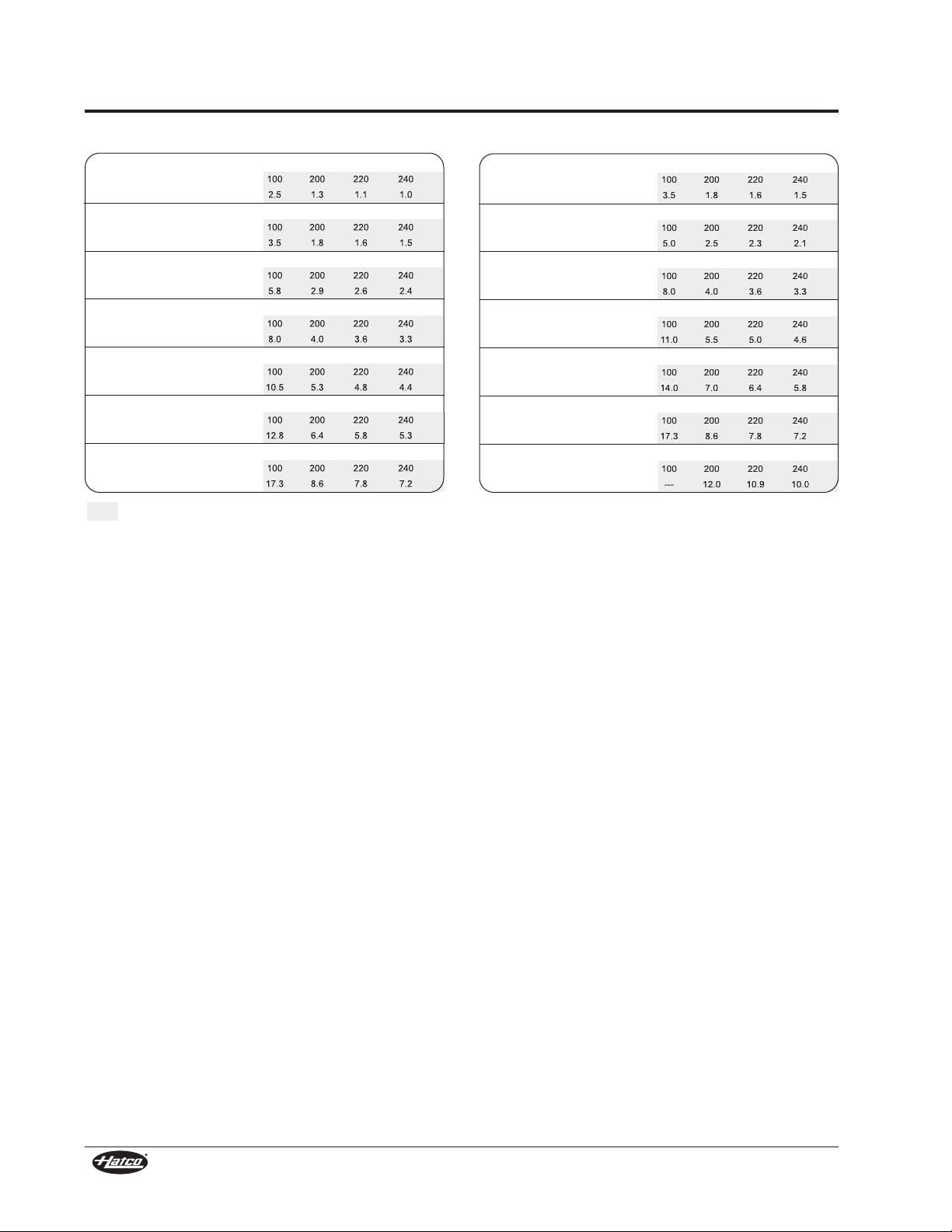
SPECIFICATIONS
Electrical Rating Chart — GR Models
Model GR-18
Voltage 120 208 240 100 200 220 240
Amps 2.1 1.2 1.0 2.5 1.3 1.1 1.0
Model GR-24
Voltage 120 208 240 100 200 220 240
Amps 2.9 1.7 1.5 3.5 1.8 1.6 1.5
Model GR-36
Voltage 120 208 240 100 200 220 240
Amps 4.8 2.8 2.4 5.8 2.9 2.6 2.4
Model GR-48
Voltage 120 208 240 100 200 220 240
Amps 6.7 3.8 3.3 8.0 4.0 3.6 3.3
Model GR-60
Voltage 120 208 240 100 200 220 240
Amps 8.8 5.0 4.4 10.5 5.3 4.8 4.4
Model GR-72
Voltage 120 208 240 100 200 220 240
Amps 10.6 6.1 5.3 12.8 6.4 5.8 5.3
Model GR-96
Voltage 120 208 240 100 200 220 240
Amps 14.4 8.3 7.2 17.3 8.6 7.8 7.2
Watts: 250 Shipping Weight: 7 lbs. (3 kg)
Watts: 350 Shipping Weight: 7 lbs. (3 kg)
Watts: 575 Shipping Weight: 10 lbs. (4.5 kg)
Watts: 800 Shipping Weight: 12 lbs. (5 kg)
Watts: 1050 Shipping Weight: 15 lbs. (7 kg)
Watts: 1275 Shipping Weight: 19 lbs. (9 kg)
Watts: 1725 Shipping Weight: 24 lbs. (11 kg)
Electrical Rating Chart — GRH Models
Model GRH-18
Voltage 120 208 240 100 200 220 240
Amps 2.9 1.7 1.5 3.5 1.8 1.6 1.5
Model GRH-24
Voltage 120 208 240 100 200 220 240
Amps 4.2 2.4 2.1 5.0 2.5 2.3 2.1
Model GRH-36
Voltage 120 208 240 100 200 220 240
Amps 6.7 3.8 3.3 8.0 4.0 3.6 3.3
Model GRH-48
Voltage 120 208 240 100 200 220 240
Amps 9.2 5.3 4.6 11.0 5.5 5.0 4.6
Model GRH-60
Voltage 120 208 240 100 200 220 240
Amps 11.7 6.7 5.8 14.0 7.0 6.4 5.8
Model GRH-72
Voltage 120 208 240 100 200 220 240
Amps 14.4 8.3 7.2 17.3 8.6 7.8 7.2
Model GRH-96
Voltage 120 208 240 100 200 220 240
Amps --- 11.5 10.0 --- 12.0 10.9 10.0
Watts: 350 Shipping Weight: 7 lbs. (3 kg)
Watts: 500 Shipping Weight: 7 lbs. (3 kg)
Watts: 800 Shipping Weight: 10 lbs. (4.5 kg)
Watts: 1100 Shipping Weight: 12 lbs. (5 kg)
Watts: 1400 Shipping Weight: 15 lbs. (7 kg)
Watts: 1725 Shipping Weight: 19 lbs. (9 kg)
Watts: 2400 Shipping Weight: 24 lbs. (11 kg)
*
The shaded areas contain electrical information for Export models only.
* Not available in 100 or 120 volts.
CE approved units for 220-230 volt utilize a 220 volt heating system; 230-240 CE units utilize a 240 volt heating system.
4
Form No. GRM-0508
Page 7
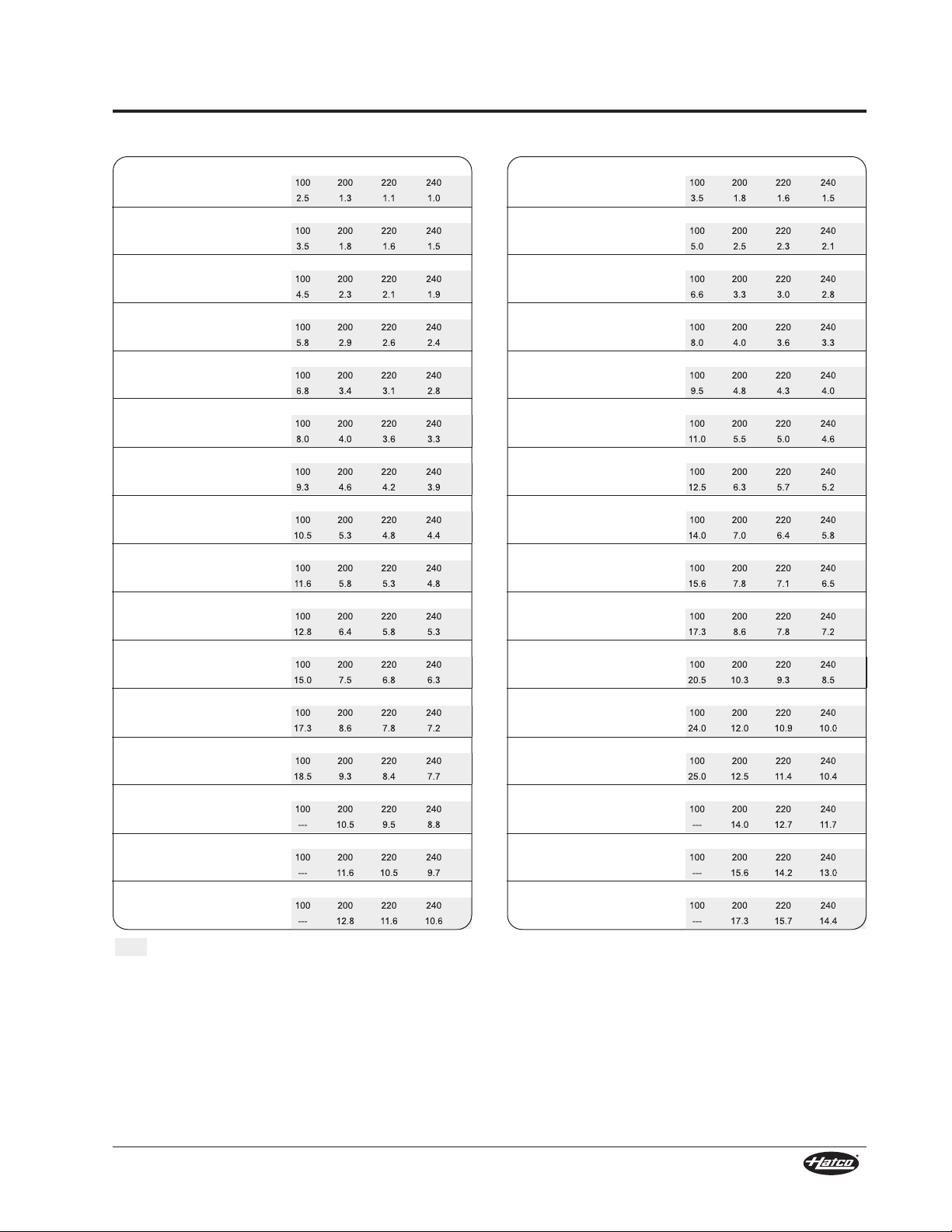
SPECIFICATIONS
Electrical Rating Chart — GRA Models Electrical Rating Chart — GRAH Models
Model GRA-18
Voltage 120 208 240 100 200 220 240
Amps 2.1 1.2 1.0 2.5 1.3 1.1 1.0
Model GRA-24
Voltage 120 208 240 100 200 220 240
Amps 2.9 1.7 1.5 3.5 1.8 1.6 1.5
Model GRA-30
Voltage 120 208 240 100 200 220 240
Amps 3.8 2.2 1.9 4.5 2.3 2.1 1.9
Model GRA-36
Voltage 120 208 240 100 200 220 240
Amps 4.8 2.8 2.4 5.8 2.9 2.6 2.4
Model GRA-42
Voltage 120 208 240 100 200 220 240
Amps 5.6 3.2 2.8 6.8 3.4 3.1 2.8
Model GRA-48
Voltage 120 208 240 100 200 220 240
Amps 6.7 3.8 3.3 8.0 4.0 3.6 3.3
Model GRA-54
Voltage 120 208 240 100 200 220 240
Amps 7.7 4.4 3.9 9.3 4.6 4.2 3.9
Model GRA-60
Voltage 120 208 240 100 200 220 240
Amps 8.8 5.0 4.4 10.5 5.3 4.8 4.4
Model GRA-66
Voltage 120 208 240 100 200 220 240
Amps 9.7 5.6 4.8 11.6 5.8 5.3 4.8
Model GRA-72
Voltage 120 208 240 100 200 220 240
Amps 10.6 6.1 5.3 12.8 6.4 5.8 5.3
Model GRA-84
Voltage 120 208 240 100 200 220 240
Amps 12.5 7.2 6.3 15.0 7.5 6.8 6.3
Model GRA-96
Voltage 120 208 240 100 200 220 240
Amps 14.4 8.3 7.2 17.3 8.6 7.8 7.2
Model GRA-108
Voltage 120 208 240 100 200 220 240
Amps 15.4 8.9 7.7 18.5 9.3 8.4 7.7
Model GRA-120
Voltage 120 208 240 100 200 220 240
Amps --- 10.1 8.8 --- 10.5 9.5 8.8
Model GRA-132
Voltage 120 208 240 100 200 220 240
Amps --- 11.2 9.7 --- 11.6 10.5 9.7
Model GRA-144
Voltage 120 208 240 100 200 220 240
Amps --- 12.3 10.6 --- 12.8 11.6 10.6
Watts: 250 Shipping Weight: 6 lbs. (3 kg)
Watts: 350 Shipping Weight: 7 lbs. (3 kg)
Watts: 450 Shipping Weight: 8 lbs. (4 kg)
Watts: 575 Shipping Weight: 9 lbs. (4 kg)
Watts: 675 Shipping Weight: 10 lbs. (5 kg)
Watts: 800 Shipping Weight: 11 lbs. (5 kg)
Watts: 925 Shipping Weight: 13 lbs. (6 kg)
Watts: 1050 Shipping Weight: 14 lbs. (6 kg)
Watts: 1160 Shipping Weight: 16 lbs. (7 kg)
Watts: 1275 Shipping Weight: 17 lbs. (8 kg)
Watts: 1500 Shipping Weight: 19 lbs. (9 kg)
•
Watts: 1725 Shipping Weight: 21 lbs. (10 kg)
•
Watts: 1850 Shipping Weight: 23 lbs. (10 kg)
†
Watts: 2100 Shipping Weight: 26 lbs. (12 kg)
†*
Watts: 2320 Shipping Weight: 30 lbs. (14 kg)
†*
Watts: 2550 Shipping Weight: 33 lbs. (15 kg)
†*
Voltage 120 208 240 100 200 220 240
Amps 2.9 1.7 1.5 3.5 1.8 1.6 1.5
Model GRAH-24
Model GRAH-18
Voltage 120 208 240 100 200 220 240
Amps 4.2 2.4 2.1 5.0 2.5 2.3 2.1
Model GRAH-30
Voltage 120 208 240 100 200 220 240
Amps 5.5 3.2 2.8 6.6 3.3 3.0 2.8
Model GRAH-36
Voltage 120 208 240 100 200 220 240
Amps 6.7 3.8 3.3 8.0 4.0 3.6 3.3
Model GRAH-42
Voltage 120 208 240 100 200 220 240
Amps 7.9 4.6 4.0 9.5 4.8 4.3 4.0
Model GRAH-48
Voltage 120 208 240 100 200 220 240
Amps 9.2 5.3 4.6 11.0 5.5 5.0 4.6
Model GRAH-54
Voltage 120 208 240 100 200 220 240
Amps 10.4 6.0 5.2 12.5 6.3 5.7 5.2
Model GRAH-60
Voltage 120 208 240 100 200 220 240
Amps 11.7 6.7 5.8 14.0 7.0 6.4 5.8
Model GRAH-66
Voltage 120 208 240 100 200 220 240
Amps 13.0 7.5 6.5 15.6 7.8 7.1 6.5
Model GRAH-72
Voltage 120 208 240 100 200 220 240
Amps 14.4 8.3 7.2 17.3 8.6 7.8 7.2
Model GRAH-84
Voltage 120 208 240 100 200 220 240
Amps 17.1 9.9 8.5 20.5 10.3 9.3 8.5
Model GRAH-96
Voltage 120 208 240 100 200 220 240
Amps 20.0 11.5 10.0 24.0 12.0 10.9 10.0
Model GRAH-108
Voltage 120 208 240 100 200 220 240
Amps 20.8 12.0 10.4 25.0 12.5 11.4 10.4
Model GRAH-120
Voltage 120 208 240 100 200 220 240
Amps --- 13.5 11.7 --- 14.0 12.7 11.7
Model GRAH-132
Voltage 120 208 240 100 200 220 240
Amps --- 15.0 13.0 --- 15.6 14.2 13.0
Model GRAH-144
Voltage 120 208 240 100 200 220 240
Amps --- 16.6 14.4 --- 17.3 15.7 14.4
Watts: 350 Shipping Weight: 6 lbs. (3 kg)
Watts: 500 Shipping Weight: 7 lbs. (3 kg)
Watts: 660 Shipping Weight: 8 lbs. (4 kg)
Watts: 800 Shipping Weight: 9 lbs. (4 kg)
Watts: 950 Shipping Weight: 10 lbs. (5 kg)
Watts: 1100 Shipping Weight: 11 lbs. (5 kg)
Watts: 1250 Shipping Weight: 13 lbs. (6 kg)
Watts: 1400 Shipping Weight: 14 lbs. (6 kg)
Watts: 1560 Shipping Weight: 16 lbs. (7 kg)
Watts: 1725 Shipping Weight: 17 lbs. (8 kg)
Watts: 2050 Shipping Weight: 19 lbs. (9 kg)
•
Watts: 2400 Shipping Weight: 21 lbs. (10 kg)
•
Watts: 2500 Shipping Weight: 23 lbs. (10 kg)
•†
Watts: 2800 Shipping Weight: 26 lbs. (12 kg)
•†*
Watts: 3120 Shipping Weight: 30 lbs. (14 kg)
†*
Watts: 3450 Shipping Weight: 33 lbs. (15 kg)
†*
The shaded areas contain electrical information for Export models only.
• 100 and 120 volt models with infinite switch require tandem (end-to-end) elements, consult factory for applications.
100 and 120 volt models may require additional switches, consult factory for applications.
† Glo-Ray models 108″ through 144″ and 120 volt models of GRA-84 and GRA-96 contain tandem (end-to-end)
elements that may be individually controlled.
* Not available in 100 or 120 volts.
CE approved units for 220-230 volt utilize a 220 volt heating system; 230-240 CE units utilize a 240 volt heating system.
Form No. GRM-0508
5
Page 8
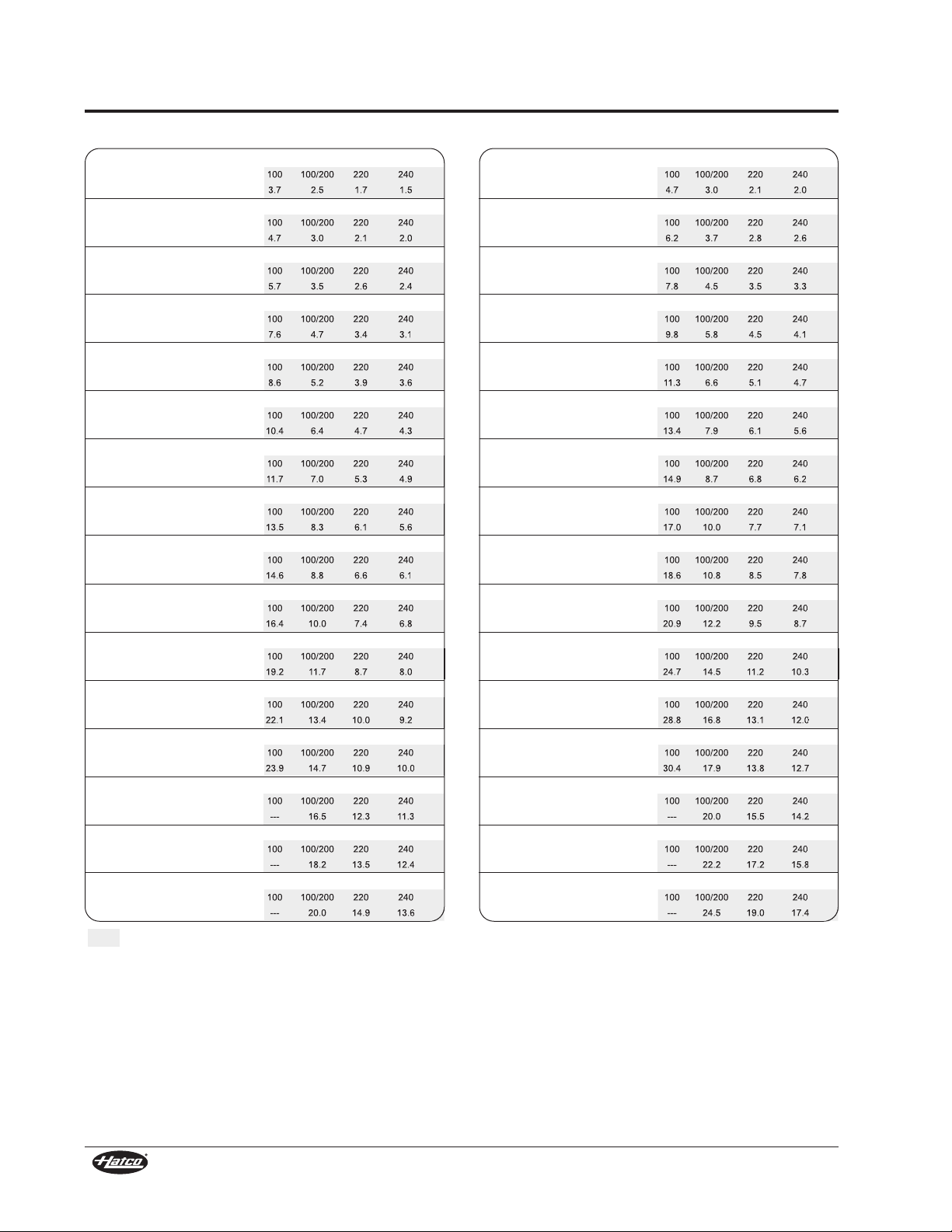
SPECIFICATIONS
Electrical Rating Chart — GRAL Models
Model GRAL-18
Voltage 120 120/208 120/240 100 100/200 220 240
Amps 3.1 2.2 2.0 3.7 2.5 1.7 1.5
Model GRAL-24
Voltage 120 120/208 120/240 100 100/200 220 240
Amps 3.9 2.7 2.5 4.7 3.0 2.1 2.0
Model GRAL-30
Voltage 120 120/208 120/240 100 100/200 220 240
Amps 4.8 3.2 2.9 5.7 3.5 2.6 2.4
Model GRAL-36
Voltage 120 120/208 120/240 100 100/200 220 240
Amps 6.3 4.3 3.9 7.6 4.7 3.4 3.1
Model GRAL-42
Voltage 120 120/208 120/240 100 100/200 220 240
Amps 7.1 4.7 4.3 8.6 5.2 3.9 3.6
Model GRAL-48
Voltage 120 120/208 120/240 100 100/200 220 240
Amps 8.7 5.8 5.3 10.4 6.4 4.7 4.3
Model GRAL-54
Voltage 120 120/208 120/240 100 100/200 220 240
Amps 9.7 6.4 5.9 11.7 7.0 5.3 4.9
Model GRAL-60
Voltage 120 120/208 120/240 100 100/200 220 240
Amps 11.3 7.5 6.9 13.5 8.3 6.1 5.6
Model GRAL-66
Voltage 120 120/208 120/240 100 100/200 220 240
Amps 12.2 8.1 7.3 14.6 8.8 6.6 6.1
Model GRAL-72
Voltage 120 120/208 120/240 100 100/200 220 240
Amps 13.6 9.1 8.3 16.4 10.0 7.4 6.8
Model GRAL-84
Voltage 120 120/208 120/240 100 100/200 220 240
Amps 16.0 10.7 9.8 19.2 11.7 8.7 8.0
Model GRAL-96
Voltage 120 120/208 120/240 100 100/200 220 240
Amps 18.4 12.3 11.2 22.1 13.4 10.0 9.2
Model GRAL-108
Voltage 120 120/208 120/240 100 100/200 220 240
Amps 19.9 13.4 12.2 23.9 14.7 10.9 10.0
Model GRAL-120
Voltage 120 120/208 120/240 100 100/200 220 240
Amps --- 15.1 13.8 --- 16.5 12.3 11.3
Model GRAL-132
Voltage 120 120/208 120/240 100 100/200 220 240
Amps --- 16.7 15.2 --- 18.2 13.5 12.4
Model GRAL-144
Voltage 120 120/208 120/240 100 100/200 220 240
Amps --- 18.3 16.6 --- 20.0 14.9 13.6
Watts: 370 Shipping Weight: 9 lbs. (4 kg)
Watts: 470 Shipping Weight: 10 lbs. (5 kg)
Watts: 570 Shipping Weight: 11 lbs. (5 kg)
Watts: 755 Shipping Weight: 13 lbs. (6 kg)
Watts: 855 Shipping Weight: 15 lbs. (7 kg)
Watts: 1040 Shipping Weight: 17 lbs. (8 kg)
Watts: 1165 Shipping Weight: 19 lbs. (9 kg)
Watts: 1350 Shipping Weight: 21 lbs. (10 kg)
Watts: 1460 Shipping Weight: 22 lbs. (10 kg)
Watts: 1635 Shipping Weight: 24 lbs. (11 kg)
Watts: 1920 Shipping Weight: 28 lbs. (13 kg)
•
Watts: 2205 Shipping Weight: 32 lbs. (15 kg)
•
Watts: 2390 Shipping Weight: 36 lbs. (16 kg)
†
Watts: 2700 Shipping Weight: 40 lbs. (18 kg)
†*
Watts: 2980 Shipping Weight: 44 lbs. (20 kg)
†*
Watts: 3270 Shipping Weight: 48 lbs. (22 kg)
†*
Electrical Rating Chart — GRAHL Models
Model GRAHL-18
Voltage 120 120/208 120/240 100 100/200 220 240
Amps 3.9 2.7 2.5 4.7 3.0 2.1 2.0
Model GRAHL-24
Voltage 120 120/208 120/240 100 100/200 220 240
Amps 5.2 3.4 3.1 6.2 3.7 2.8 2.6
Model GRAHL-30
Voltage 120 120/208 120/240 100 100/200 220 240
Amps 6.5 4.2 3.8 7.8 4.5 3.5 3.3
Model GRAHL-36
Voltage 120 120/208 120/240 100 100/200 220 240
Amps 8.2 5.3 4.8 9.8 5.8 4.5 4.1
Model GRAHL-42
Voltage 120 120/208 120/240 100 100/200 220 240
Amps 9.4 6.1 5.5 11.3 6.6 5.1 4.7
Model GRAHL-48
Voltage 120 120/208 120/240 100 100/200 220 240
Amps 11.2 7.3 6.6 13.4 7.9 6.1 5.6
Model GRAHL-54
Voltage 120 120/208 120/240 100 100/200 220 240
Amps 12.4 8.0 7.2 14.9 8.7 6.8 6.2
Model GRAHL-60
Voltage 120 120/208 120/240 100 100/200 220 240
Amps 14.2 9.2 8.3 17.0 10.0 7.7 7.1
Model GRAHL-66
Voltage 120 120/208 120/240 100 100/200 220 240
Amps 15.5 10.0 9.0 18.6 10.8 8.5 7.8
Model GRAHL-72
Voltage 120 120/208 120/240 100 100/200 220 240
Amps 17.4 11.3 10.2 20.9 12.2 9.5 8.7
Model GRAHL-84
Voltage 120 120/208 120/240 100 100/200 220 240
Amps 20.6 13.4 12.0 24.7 14.5 11.2 10.3
Model GRAHL-96
Voltage 120 120/208 120/240 100 100/200 220 240
Amps 24.0 15.5 14.0 28.8 16.8 13.1 12.0
Model GRAHL-108
Voltage 120 120/208 120/240 100 100/200 220 240
Amps 25.3 16.5 14.9 30.4 17.9 13.8 12.7
Model GRAHL-120
Voltage 120 120/208 120/240 100 100/200 220 240
Amps --- 18.5 16.7 --- 20.0 15.5 14.2
Model GRAHL-132
Voltage 120 120/208 120/240 100 100/200 220 240
Amps --- 20.5 18.5 --- 22.2 17.2 15.8
Model GRAHL-144
Voltage 120 120/208 120/240 100 100/200 220 240
Amps --- 22.6 20.4 --- 24.5 19.0 17.4
Watts: 470 Shipping Weight: 9 lbs. (4 kg)
Watts: 620 Shipping Weight: 10 lbs. (5 kg)
Watts: 780 Shipping Weight: 11 lbs. (5 kg)
Watts: 980 Shipping Weight: 13 lbs. (6 kg)
Watts: 1130 Shipping Weight: 15 lbs. (7 kg)
Watts: 1340 Shipping Weight: 17 lbs. (8 kg)
Watts: 1490 Shipping Weight: 19 lbs. (9 kg)
Watts: 1700 Shipping Weight: 21 lbs. (10 kg)
Watts: 1860 Shipping Weight: 22 lbs. (10 kg)
•
Watts: 2085 Shipping Weight: 24 lbs. (11 kg)
•
Watts: 2470 Shipping Weight: 28 lbs. (13 kg)
•
Watts: 2880 Shipping Weight: 32 lbs. (15 kg)
•
Watts: 3040 Shipping Weight: 36 lbs. (16 kg)
†
Watts: 3400 Shipping Weight: 40 lbs. (18 kg)
†*
Watts: 3780 Shipping Weight: 44 lbs. (20 kg)
†*
Watts: 4170 Shipping Weight: 48 lbs. (22 kg)
†*
The shaded areas contain electrical information for Export models only.
• 100 and 120 volt models with infinite switch may require tandem (end-to-end) elements, consult factory for applications.
100 and 120 volt models may require additional switches, consult factory for applications.
† Glo-Ray models 108″ through 144″ and 120 volt models of GRAL-84 and GRAL-96 contain tandem (end-to-end)
elements that may be individually controlled.
* Not available in 100 or 120 volts.
CE approved units for 220-230 volt utilize a 220 volt heating system; 230-240 CE units utilize a 240 volt heating system.
NOTE: GRAL & GRAHL Models that have multiple voltages listed, such
as 120/208, 120/240 or 100/200, have multiple circuits. For
example a 120/208 volt unit utilizes 120 volts for light circuit and
208 volts for the heat circuit(s). Consult Electrical Diagram
supplied with the unit for specific information.
CAUTION! Strip heaters equipped with incandescent lights
that require a circuit breaker larger than 20 amps for the
heat element must have a separate circuit breaker for the
incandescent lights that is 20 amps or less.
6
Form No. GRM-0508
Page 9
SPECIFICATIONS
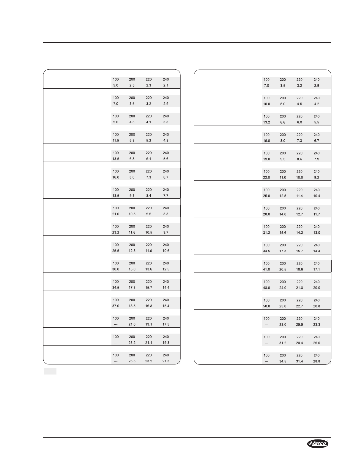
Electrical Rating Chart —
GRA-XXD Models
Model GRA-18D
Voltage 120 208 240 100 200 220 240
Amps 4.2 2.4 2.1 5.0 2.5 2.3 2.1
Model GRA-24D
Voltage 120 208 240 100 200 220 240
Amps 5.8 3.4 2.9 7.0 3.5 3.2 2.9
Model GRA-30D
Voltage 120 208 240 100 200 220 240
Amps 7.5 4.3 3.8 9.0 4.5 4.1 3.8
Model GRA-36D
Voltage 120 208 240 100 200 220 240
Amps 9.6 5.5 4.8 11.5 5.8 5.2 4.8
Model GRA-42D
Voltage 120 208 240 100 200 220 240
Amps 11.3 6.5 5.6 13.5 6.8 6.1 5.6
Model GRA-48D
Voltage 120 208 240 100 200 220 240
Amps 13.3 7.7 6.7 16.0 8.0 7.3 6.7
Model GRA-54D
Voltage 120 208 240 100 200 220 240
Amps 15.4 8.9 7.7 18.5 9.3 8.4 7.7
Model GRA-60D
Voltage 120 208 240 100 200 220 240
Amps 17.5 10.1 8.8 21.0 10.5 9.5 8.8
Model GRA-66D
Voltage 120 208 240 100 200 220 240
Amps 19.3 11.2 9.7 23.2 11.6 10.5 9.7
Model GRA-72D
Voltage 120 208 240 100 200 220 240
Amps 21.3 12.3 10.6 25.5 12.8 11.6 10.6
Model GRA-84D
Voltage 120 208 240 100 200 220 240
Amps 25.0 14.4 12.5 30.0 15.0 13.6 12.5
Model GRA-96D
Voltage 120 208 240 100 200 220 240
Amps 28.8 16.6 14.4 34.5 17.3 15.7 14.4
Model GRA-108D
Voltage 120 208 240 100 200 220 240
Amps 30.8 17.8 15.4 37.0 18.5 16.8 15.4
Model GRA-120D
Voltage 120 208 240 100 200 220 240
Amps --- 20.2 17.5 --- 21.0 19.1 17.5
Model GRA-132D
Voltage 120 208 240 100 200 220 240
Amps --- 22.3 19.3 --- 23.2 21.1 19.3
Model GRA-144D
Voltage 120 208 240 100 200 220 240
Amps --- 24.5 21.3 --- 25.5 23.2 21.3
Watts: 500 Shipping Weight: 14 lbs. (6 kg)
Watts: 700 Shipping Weight: 16 lbs. (7 kg)
Watts: 900 Shipping Weight: 18 lbs. (8 kg)
Watts: 1150 Shipping Weight: 21 lbs. (10 kg)
Watts: 1350 Shipping Weight: 24 lbs. (11 kg)
Watts: 1600 Shipping Weight: 27 lbs. (12 kg)
Watts: 1850 Shipping Weight: 30 lbs. (14 kg)
Watts: 2100 Shipping Weight: 34 lbs. (15 kg)
Watts: 2320 Shipping Weight: 37 lbs. (17 kg)
•
Watts: 2550 Shipping Weight: 41 lbs. (19 kg)
•
Watts: 3000 Shipping Weight: 44 lbs. (20 kg)
†
Watts: 3450 Shipping Weight: 52 lbs. (24 kg)
†
Watts: 3700 Shipping Weight: 59 lbs. (27 kg)
†
Watts: 4200 Shipping Weight: 66 lbs. (30 kg)
†*
Watts: 4640 Shipping Weight: 73 lbs. (33 kg)
†*
Watts: 5100 Shipping Weight: 80 lbs. (36 kg)
†*
Electrical Rating Chart —
GRAH-XXD Models
Voltage 120 208 240 100 200 220 240
Amps 5.8 3.4 2.9 7.0 3.5 3.2 2.9
Model GRAH-24D
Model GRAH-18D
Voltage 120 208 240 100 200 220 240
Amps 8.3 4.8 4.2 10.0 5.0 4.5 4.2
Model GRAH-30D
Voltage 120 208 240 100 200 220 240
Amps 11.0 6.3 5.5 13.2 6.6 6.0 5.5
Model GRAH-36D
Voltage 120 208 240 100 200 220 240
Amps 13.3 7.7 6.7 16.0 8.0 7.3 6.7
Model GRAH-42D
Voltage 120 208 240 100 200 220 240
Amps 15.8 9.1 7.9 19.0 9.5 8.6 7.9
Model GRAH-48D
Voltage 120 208 240 100 200 220 240
Amps 18.3 10.6 9.2 22.0 11.0 10.0 9.2
Model GRAH-54D
Voltage 120 208 240 100 200 220 240
Amps 20.8 12.0 10.4 25.0 12.5 11.4 10.4
Model GRAH-60D
Voltage 120 208 240 100 200 220 240
Amps 23.3 13.5 11.7 28.0 14.0 12.7 11.7
Model GRAH-66D
Voltage 120 208 240 100 200 220 240
Amps 26.0 15.0 13.0 31.2 15.6 14.2 13.0
Model GRAH-72D
Voltage 120 208 240 100 200 220 240
Amps 28.8 16.6 14.4 34.5 17.3 15.7 14.4
Model GRAH-84D
Voltage 120 208 240 100 200 220 240
Amps 34.2 19.7 17.1 41.0 20.5 18.6 17.1
Model GRAH-96D
Voltage 120 208 240 100 200 220 240
Amps 40.0 23.1 20.0 48.0 24.0 21.8 20.0
Model GRAH-108D
Voltage 120 208 240 100 200 220 240
Amps 41.7 24.0 20.8 50.0 25.0 22.7 20.8
Model GRAH-120D
Voltage 120 208 240 100 200 220 240
Amps --- 26.9 23.3 --- 28.0 25.5 23.3
Model GRAH-132D
Voltage 120 208 240 100 200 220 240
Amps --- 30.0 26.0 --- 31.2 28.4 26.0
Model GRAH-144D
Voltage 120 208 240 100 200 220 240
Amps --- 33.2 28.8 --- 34.5 31.4 28.8
Watts: 700 Shipping Weight: 14 lbs. (6 kg)
Watts: 1000 Shipping Weight: 16 lbs. (7 kg)
Watts: 1320 Shipping Weight: 18 lbs. (8 kg)
Watts: 1600 Shipping Weight: 21 lbs. (10 kg)
Watts: 1900 Shipping Weight: 24 lbs. (11 kg)
Watts: 2200 Shipping Weight: 27 lbs. (12 kg)
Watts: 2500 Shipping Weight: 30 lbs. (14 kg)
Watts: 2800 Shipping Weight: 34 lbs. (15 kg)
Watts: 3120 Shipping Weight: 37 lbs. (17 kg)
•
Watts: 3450 Shipping Weight: 41 lbs. (19 kg)
•
Watts: 4100 Shipping Weight: 44 lbs. (20 kg)
†
Watts: 4800 Shipping Weight: 52 lbs. (24 kg)
†
Watts: 5000 Shipping Weight: 59 lbs. (27 kg)
†
Watts: 5600 Shipping Weight: 66 lbs. (30 kg)
†*
Watts: 6240 Shipping Weight: 73 lbs. (33 kg)
†*
Watts: 6900 Shipping Weight: 80 lbs. (36 kg)
†*
The shaded areas contain electrical information for Export models only.
• 100 and 120 volt models with infinite switch may require tandem (end-to-end) elements, consult factory for applications.
100 and 120 volt models may require additional switches, consult factory for applications.
† Glo-Ray models 108″ through 144″ and 120 volt models of GRA-84D and GRA-96D contain tandem (end-to-end) elements that may
be individually controlled.
* Not available in 100 or 120 volts.
Form No. GRM-0508
7
Page 10

SPECIFICATIONS
Electrical Rating Chart —
GRAL-XXD Models
Model GRAL-18D
Voltage 120 120/208 120/240 100 100/200 220 240
Amps 5.2 3.4 3.1 6.2 3.7 2.8 2.6
Model GRAL-24D
Voltage 120 120/208 120/240 100 100/200 220 240
Amps 6.8 4.4 3.9 8.2 4.7 3.7 3.4
Model GRAL-30D
Voltage 120 120/208 120/240 100 100/200 220 240
Amps 8.5 5.3 4.8 10.2 5.7 4.6 4.3
Model GRAL-36D
Voltage 120 120/208 120/240 100 100/200 220 240
Amps 11.1 7.0 6.3 13.3 7.6 6.0 5.5
Model GRAL-42D
Voltage 120 120/208 120/240 100 100/200 220 240
Amps 12.8 8.0 7.1 15.3 8.6 7.0 6.4
Model GRAL-48D
Voltage 120 120/208 120/240 100 100/200 220 240
Amps 15.3 9.7 8.7 18.4 10.4 8.4 7.7
Model GRAL-54D
Voltage 120 120/208 120/240 100 100/200 220 240
Amps 17.4 10.9 9.7 20.9 11.7 9.5 8.7
Model GRAL-60D
Voltage 120 120/208 120/240 100 100/200 220 240
Amps 20.0 12.6 11.3 24.0 13.5 10.9 10.0
Model GRAL-66D
Voltage 120 120/208 120/240 100 100/200 220 240
Amps 21.8 13.7 12.2 26.2 14.6 11.9 10.9
Model GRAL-72D
Voltage 120 120/208 120/240 100 100/200 220 240
Amps 24.3 15.3 13.6 29.1 16.4 13.2 12.1
Model GRAL-84D
Voltage 120 120/208 120/240 100 100/200 220 240
Amps 28.5 17.9 16.0 34.2 19.2 15.5 14.3
Model GRAL-96D
Voltage 120 120/208 120/240 100 100/200 220 240
Amps 32.8 20.6 18.4 39.3 22.1 17.9 16.4
Model GRAL-108D
Voltage 120 120/208 120/240 100 100/200 220 240
Amps 35.3 22.3 19.9 42.4 23.9 19.3 17.7
Model GRAL-120D
Voltage 120 120/208 120/240 100 100/200 220 240
Amps -- 25.2 22.5 --- 27.0 21.8 20.0
Model GRAL-132D
Voltage 120 120/208 120/240 100 100/200 220 240
Amps --- 27.8 24.8 --- 29.8 24.1 22.1
Model GRAL-144D
Voltage 120 120/208 120/240 100 100/200 220 240
Amps --- 30.5 27.3 --- 32.7 26.5 24.3
Watts: 620 Shipping Weight: 14 lbs. (6 kg)
Watts: 820 Shipping Weight: 16 lbs. (7 kg)
Watts: 1020 Shipping Weight: 19 lbs. (9 kg)
Watts: 1330 Shipping Weight: 22 lbs. (10 kg)
Watts: 1530 Shipping Weight: 25 lbs. (11 kg)
Watts: 1840 Shipping Weight: 29 lbs. (13 kg)
Watts: 2090 Shipping Weight: 33 lbs. (15 kg)
Watts: 2400 Shipping Weight: 37 lbs. (17 kg)
Watts: 2620 Shipping Weight: 40 lbs. (18 kg)
Watts: 2910 Shipping Weight: 42 lbs. (19 kg)
Watts: 3420 Shipping Weight: 47 lbs. (21 kg)
•
Watts: 3930 Shipping Weight: 56 lbs. (25 kg)
•
Watts: 4240 Shipping Weight: 64 lbs. (29 kg)
†
Watts: 4800 Shipping Weight: 72 lbs. (33 kg)
†*
Watts: 5300 Shipping Weight: 79 lbs. (36 kg)
†*
Watts: 5820 Shipping Weight: 86 lbs. (39 kg)
†*
Electrical Rating Chart —
GRAHL-XXD Models
Model GRAHL-18D
Voltage 120 120/208 120/240 100 100/200 220 240
Amps 6.8 4.4 3.9 8.2 4.7 3.7 3.4
Model GRAHL-24D
Voltage 120 120/208 120/240 100 100/200 220 240
Amps 9.3 5.8 5.2 11.2 6.2 5.1 4.7
Model GRAHL-30D
Voltage 120 120/208 120/240 100 100/200 220 240
Amps 12.0 7.3 6.5 14.4 7.8 6.5 6.0
Model GRAHL-36D
Voltage 120 120/208 120/240 100 100/200 220 240
Amps 14.8 9.2 8.2 17.8 9.8 8.1 7.4
Model GRAHL-42D
Voltage 120 120/208 120/240 100 100/200 220 240
Amps 17.3 10.6 9.4 20.8 11.3 9.5 8.7
Model GRAHL-48D
Voltage 120 120/208 120/240 100 100/200 220 240
Amps 20.3 12.6 11.2 24.4 13.4 11.1 10.2
Model GRAHL-54D
Voltage 120 120/208 120/240 100 100/200 220 240
Amps 22.8 14.0 12.4 27.4 14.9 12.5 11.4
Model GRAHL-60D
Voltage 120 120/208 120/240 100 100/200 220 240
Amps 25.8 16.0 14.2 31.0 17.0 14.1 12.9
Model GRAHL-66D
Voltage 120 120/208 120/240 100 100/200 220 240
Amps 28.5 17.5 15.5 34.2 18.6 15.5 14.3
Model GRAHL-72D
Voltage 120 120/208 120/240 100 100/200 220 240
Amps 31.8 19.6 17.4 38.1 20.9 17.3 15.9
Model GRAHL-84D
Voltage 120 120/208 120/240 100 100/200 220 240
Amps 37.7 23.2 20.6 45.2 24.7 20.5 18.8
Model GRAHL-96D
Voltage 120 120/208 120/240 100 100/200 220 240
Amps 44.0 27.1 24.0 52.8 28.8 24.0 22.0
Model GRAHL-108D
Voltage 120 120/208 120/240 100 100/200 220 240
Amps 46.2 28.5 25.3 55.4 30.4 25.2 23.1
Model GRAHL-120D
Voltage 120 120/208 120/240 100 100/200 220 240
Amps --- 31.9 28.3 --- 34.0 28.2 25.8
Model GRAHL-132D
Voltage 120 120/208 120/240 100 100/200 220 240
Amps --- 35.5 31.5 --- 37.8 31.4 28.8
Model GRAHL-144D
Voltage 120 120/208 120/240 100 100/200 220 240
Amps --- 39.2 34.8 --- 41.7 34.6 31.8
Watts: 820 Shipping Weight: 14 lbs. (6 kg)
Watts: 1120 Shipping Weight: 16 lbs. (7 kg)
Watts: 1440 Shipping Weight: 19 lbs. (9 kg)
Watts: 1780 Shipping Weight: 22 lbs. (10 kg)
Watts: 2080 Shipping Weight: 25 lbs. (11 kg)
Watts: 2440 Shipping Weight: 29 lbs. (13 kg)
Watts: 2740 Shipping Weight: 33 lbs. (15 kg)
Watts: 3100 Shipping Weight: 37 lbs. (17 kg)
Watts: 3420 Shipping Weight: 39 lbs. (18 kg)
•
Watts: 3810 Shipping Weight: 42 lbs. (19 kg)
•
Watts: 4520 Shipping Weight: 47 lbs. (21 kg)
†
Watts: 5280 Shipping Weight: 56 lbs. (25 kg)
†
Watts: 5540 Shipping Weight: 64 lbs. (29 kg)
†
Watts: 6200 Shipping Weight: 72 lbs. (33 kg)
†*
Watts: 6900 Shipping Weight: 79 lbs. (36 kg)
†*
Watts: 7620 Shipping Weight: 86 lbs. (39 kg)
†*
The shaded areas contain electrical information for Export models only.
• 100 and 120 volt models with infinite switch may require tandem (end-to-end) elements, consult factory for applications.
100 and 120 volt models may require additional switches, consult factory for applications.
† Glo-Ray models 108″ through 144″ and 120 volt models of GRAL-84D and GRAL-96D contain tandem (end-to-end) elements that
may be individually controlled.
* Not available in 100 or 120 volts.
CE approved units for 220-230 volt utilize a 220 volt heating system; 230-240 CE units utilize a 240 volt heating system.
8
Form No. GRM-0508
Page 11

SPECIFICATIONS
CAUTION
Electrical Rating Chart — GRN Models Electrical Rating Chart — GRNH Models
Model GRN-18
Voltage 120 208 240 100 200 220 240
Amps 2.1 1.2 1.0 2.5 1.3 1.1 1.0
Model GRN-24
Voltage 120 208 240 100 200 220 240
Amps 2.9 1.7 1.5 3.5 1.8 1.6 1.5
Model GRN-30
Voltage 120 208 240 100 200 220 240
Amps 3.8 2.2 1.9 4.5 2.3 2.1 1.9
Model GRN-36
Voltage 120 208 240 100 200 220 240
Amps 4.8 2.8 2.4 5.8 2.9 2.6 2.4
Model GRN-42
Voltage 120 208 240 100 200 220 240
Amps 5.6 3.2 2.8 6.8 3.4 3.1 2.8
Model GRN-48
Voltage 120 208 240 100 200 220 240
Amps 6.7 3.8 3.3 8.0 4.0 3.6 3.3
Model GRN-54
Voltage 120 208 240 100 200 220 240
Amps 7.7 4.4 3.9 9.3 4.6 4.2 3.9
Model GRN-60
Voltage 120 208 240 100 200 220 240
Amps 8.8 5.0 4.4 10.5 5.3 4.8 4.4
Model GRN-66
Voltage 120 208 240 100 200 220 240
Amps 9.7 5.6 4.8 11.6 5.8 5.3 4.8
Model GRN-72
Voltage 120 208 240 100 200 220 240
Amps 10.6 6.1 5.3 12.8 6.4 5.8 5.3
Watts: 250 Shipping Weight: 6 lbs. (3 kg)
Watts: 350 Shipping Weight: 7 lbs. (3 kg)
Watts: 450 Shipping Weight: 8 lbs. (4 kg)
Watts: 575 Shipping Weight: 9 lbs. (4 kg)
Watts: 675 Shipping Weight: 10 lbs. (5 kg)
Watts: 800 Shipping Weight: 11 lbs. (5 kg)
Watts: 925 Shipping Weight: 13 lbs. (6 kg)
Watts: 1050 Shipping Weight: 14 lbs. (6 kg)
Watts: 1160 Shipping Weight: 16 lbs. (7 kg)
Watts: 1275 Shipping Weight: 17 lbs. (8 kg)
Voltage 120 208 240 100 200 220 240
Amps 2.9 1.7 1.5 3.5 1.8 1.6 1.5
Model GRNH-24
Model GRNH-18
Voltage 120 208 240 100 200 220 240
Amps 4.2 2.4 2.1 5.0 2.5 2.3 2.1
Model GRNH-30
Voltage 120 208 240 100 200 220 240
Amps 5.5 3.2 2.8 6.6 3.3 3.0 2.8
Model GRNH-36
Voltage 120 208 240 100 200 220 240
Amps 6.7 3.8 3.3 8.0 4.0 3.6 3.3
Model GRNH-42
Voltage 120 208 240 100 200 220 240
Amps 7.9 4.6 4.0 9.5 4.8 4.3 4.0
Model GRNH-48
Voltage 120 208 240 100 200 220 240
Amps 9.2 5.3 4.6 11.0 5.5 5.0 4.6
Model GRNH-54
Voltage 120 208 240 100 200 220 240
Amps 10.4 6.0 5.2 12.5 6.3 5.7 5.2
Model GRNH-60
Voltage 120 208 240 100 200 220 240
Amps 11.7 6.7 5.8 14.0 7.0 6.4 5.8
Model GRNH-66
Voltage 120 208 240 100 200 220 240
Amps 13.0 7.5 6.5 15.6 7.8 7.1 6.5
Model GRNH-72
Voltage 120 208 240 100 200 220 240
Amps 14.4 8.3 7.2 17.3 8.6 7.8 7.2
Watts: 350 Shipping Weight: 6 lbs. (3 kg)
Watts: 500 Shipping Weight: 7 lbs. (3 kg)
Watts: 660 Shipping Weight: 8 lbs. (4 kg)
Watts: 800 Shipping Weight: 9 lbs. (4 kg)
Watts: 950 Shipping Weight: 10 lbs. (5 kg)
Watts: 1100 Shipping Weight: 11 lbs. (5 kg)
Watts: 1250 Shipping Weight: 13 lbs. (6 kg)
Watts: 1400 Shipping Weight: 14 lbs. (6 kg)
Watts: 1560 Shipping Weight: 16 lbs. (7 kg)
*
Watts: 1725 Shipping Weight: 17 lbs. (8 kg)
*
The shaded areas contain electrical information for Export models only.
* 120 volt models not available for use with remote infinite switches.
CE approved units for 220-230 volt utilize a 220 volt heating system; 230-240 CE units utilize a 240 volt heating system.
NOTE: GRAL & GRAHL Models that have multiple
voltages listed, such as 120/208, 120/240 or
100/200, have multiple circuits. For
example a 120/208 volt unit utilizes 120
volts for light circuit and 208 volts for the
heat circuit(s). Consult Electrical Diagram
supplied with the unit for specific
information.
Strip heaters equipped with incandescent lights
that require a circuit breaker larger than 20
amps for the heat element must have a separate
circuit breaker for the incandescent lights that is
20 amps or less.
Form No. GRM-0508
9
Page 12

SPECIFICATIONS
A
C
B
D
A
C
B
D
A
C
B
D
A
B
D
Dimensions
Width Depth Depth Height
Models (A) (B) (C) (D)
GR and 18″ – 96″ 6″ 23″ 2-1/2″
GRH (457 – 2438 mm) (152 mm) (584 mm) (64 mm)
GRA and 18″ – 144″ 6″ 23″ 2-1/2″
GRAH (457 – 3658 mm) (152 mm) (584 mm) (64 mm)
NOTE: Unit shown with optional 9-3/8″ (238 mm)
sneeze guards and mounting flanges. Not
available for retrofit or on GR and GRH
models.
Figure 6. Dimensions — GR, GRH, GRA, and
GRAH Models
Models (A) (B) (C) (D)
Width Depth Depth Height
GRAL and 18″ – 144″ 9″ 26″ 2-1/2″
GRAHL (457 – 3658 mm) (229 mm) (660 mm) (64 mm)
NOTE: Unit shown with optional 9-3/8″ (238 mm)
sneeze guards and mounting flanges. Not
available for retrofit.
Width Depth*Depth*Height
Models (A) (B) (C) (D)
GRA-XXD and 18″ – 144″ 15″ 32″ 2-1/2″
GRAH-XXD (457 – 3658mm) (381 mm) (813 mm) (64 mm)
GRAL-XXD and 18″ – 144″ 15″ 32″ 2-1/2″
GRAHL-XXD (457– 3658 mm) (381 mm) (813 mm) (64 mm)
* Dimension shown is standard with 3″ (76 mm) spacer; when
used with 6″ (152 mm) spacer, add 3″ (76 mm).
NOTE: Unit shown with optional 9-3/8″ (238 mm)
sneeze guards and mounting flanges. Not
available for retrofit.
Figure 7. Dimensions — GRAL and GRAHL Models
Figure 8. Dimensions — GRA-D, GRAH-D,
GRAL-D, and GRAHL-D Models
Models (A) (B) (C)
GRN and 18″ – 72″ 4″ 2″
GRNH (457 – 1829 mm) (102 mm) (51 mm)
Width Depth Height
10
Figure 9. Dimensions — GRN and GRNH Models
Form No. GRM-0508
Page 13

INSTALLATION
NOTICE
CAUTION
WARNING
NOTICE
General
Use the information in this section to prepare for
installation of the strip heater. Make sure to locate
the specific information for the model of strip heater
and type of installation.
FIRE HAZARD:
• Locate the unit the correct distance from
combustible walls and materials. If safe
distances are not maintained, discoloration
or combustion could occur. Refer to specific
installation and mounting information in this
manual for proper clearances.
• Make sure to follow the installation
information listed below for specific strip
heaters. If safe distances are not maintained,
discoloration or combustion could occur.
a. Do not install standard wattage strip
heaters (GR, GRA, GRN, GRAL Series) less
than 10″ (254 mm) above combustible
surfaces.
b. Do not install high wattage strip heaters
(GRH, GRAH, GRNH, GRAHL Series) less
than 13-1/2″ (343 mm) above combustible
surfaces.
c. Do not install dual strip heaters (GRA-XXD,
GRAH-XXD, GRAL-XXD, and GRAHL-XXD
Series) above combustible surfaces.
e. Install all single strip heaters with a
minimum distance of 3″ (76 mm) from a
combustible wall or adjacent surface.
To ensure safe and proper operation, refer to the
Clearance Requirements listed in the Installation
section of this manual.
1. Remove the unit from the shipping carton and
remove all packing materials.
2. Remove the information packet.
NOTE: To prevent delay in obtaining warranty
coverage, fill out and mail in the warranty
card to Hatco.
NOTE: If unit is equipped with optional equipment,
see the ACCESSORIES section near the
back of this manual.
Dual Mounting
When mounting units side-by-side, a space not less
than 3″ (76 mm) must be maintained between units.
Dual units ordered from the factory are shipped with
a pre-assembled 3″ (76 mm) or 6″ (152 mm) spacer.
NOTE: Dual units are available with aluminum
housings only.
Installation of two or more separate units with
less than 3″ (76 mm) between housings may
result in premature failure of component parts.
Failure to provide proper spacing may result in
heat damage to electrical components.
Under Shelf Mounting
When mounting a unit under a shelf, use adjustable
angle brackets to assure proper spacing. Remote
control enclosures are recommended to keep
switches out of the heat zone and prevent
premature failure.
Pass-Through
If pass-through area is 12″ to 16″ (305 to 406 mm)
deep, the standard wattage or high wattage single
unit can be used. For a 20″ to 24″ (508 to 610 mm)
deep pass-through area, a dual unit in either
standard or high wattage is recommended.
Installation of multiple units must have a minimum
spacing of 3″ (76 mm) between heaters.
Heat damage to countertop material such as
Corian
stainless steel) is not covered under the Hatco
warranty. Contact the manufacturer of the base
material for temperature limits and application
information before installing the unit.
To prevent unit failure from excessive heat, do
not add a decorative soffit to hide a passthrough mounted strip heater.
NOTE: Contact the countertop manufacturer of the
Form No. GRM-0508
®
and similar products (other than
base material for application information
and surface temperature limits before
installing the unit.
T-Legs or C-Legs
Do not mount units longer than 60″ (1524 mm)
on T-legs or C-legs.
Over Steam Table
When mounting over a steam table, a remote
control switch enclosure must be installed.
11
Page 14

INSTALLATION
10″–14″
(254–356 mm)
Standard Wattage
Height
14″–18″
(356–457 mm)
18″ (457 mm)
24″ (610 mm)
High Wattage
Height
15″ (381 mm)
21″ (533 mm)
14″–18″
(356–457 mm)
10″–14″
(254–356 mm)
Standard Wattage
Height
High Wattage
Height
4″–6″
(102–152 mm)
12″ (305 mm)
8″–11″
(203–279 mm)
Standard Wattage
Height
High Wattage
Height
11″ –14″
(279–356 mm)
Add 3″ for
units with lights.
CL-Low CL-High
11-1/8″
(283 mm)
12-1/4″
(311 mm)
Mounting Height Requirements
Figure 10. Recommended Element Height for the
GR, GRA, GRH, GRN, GRAH, GRAL, GRNH, and
GRAHL models in all lengths (excluding dual models).
Assembly
Glo-Ray Strip Heaters are shipped with most
components pre-assembled. Dual units are
available with a required 3″ (76 mm) or 6″ (152 mm)
spacer pre-assembled at the factory.
Optional sneeze guards, mounting equipment, and
remote control enclosures must be installed on
location.
Portable Surface Mounting
Single strip heater units can be mounted on C-Leg
or T-Leg stands for portable use. Portable units are
available in 120V only and are required to have a
power cord and plug connection.
NOTE: C-Legs and T-Legs are not to be used with
dual strip heater units.
C-Leg Stand Mounting
Two types of C-Legs are available.
• CL-Low = 10″ (254 mm) height, for standard
wattage strip heaters up to 5′
(1524 mm) in width only.
• CL-High = 13-1/2″ (343 mm) height, for high
wattage strip heaters up to 5′
(1524 mm) in width only.
Figure 11. Recommended Element Height for the
GRA-D, GRAH-D, GRAL-D & GRAHL-D dual models
with a 3″ (76 mm) spacer in all lengths.
Figure 12. Recommended Element Height for the
GRA-D, GRAH-D, GRAL-D & GRAHL-D dual models
with a 6″ (152 mm) spacer in all lengths.
Figure 13. C-Leg Footprint Dimensions
Perform the following procedure to install a C-Leg
stand on each end of the unit.
1. Position the unit upside-down on a flat surface.
2. Install sneeze guard(s), if required (refer to the
“Sneeze Guard Installation” procedure in this
section).
3. Remove the two screws and hanger tabs from
the end of the unit.
4. Remove the one end plate screw that aligns
with the lowest mounting hole on the C-Leg (see
Figure 14).
5. Align the three mounting holes on the C-Leg
with the three holes on the unit. Secure the leg
to the unit with the three screws removed in the
previous steps.
12
Form No. GRM-0508
Page 15

Figure 14. C-Leg Stand
12″
(305 mm)
Removed
Hanger Tabs
C-Leg
T-Leg
Removed
Hanger Tabs
Mounting Bracket
T-Leg Stand Mounting
T-Leg stands are available in the following heights:
• Standard wattage units = 10″ (254 mm)
• High wattage units = 13-1/2″ (343 mm)
16″ (406 mm)
18″ (457 mm).
INSTALLATION
5. Align the two mounting holes on the small “T” of
the T-Leg with the two holes on the end of the
unit. Secure the leg to the unit with the two
screws removed in the previous step.
6. Align the single mounting hole on the vertical
post of the T-Leg with the hole on the mounting
bracket. Secure with the supplied screw.
Figure 16. T-Leg Stand End Mounting
Figure 15. T-Leg Footprint Dimension
Perform the following procedure to install a T-Leg
stand on each end of the unit.
1. Position the unit upside-down on a flat surface.
2. Position the mounting bracket on the underside
of the unit and remove the two screws on the
unit that match up with the holes on the
mounting bracket.
3. Secure the mounting bracket to the unit with the
two screws removed in the previous step.
4. Remove the two screws and hanger tabs from
the end of the unit.
Form No. GRM-0508
13
Page 16

INSTALLATION
A
B
C
Pass-Through Shelf
Back Wall
Counter
C
Pass-Through Shelf
Back Wall
Counter
A
B
Minimum Clearance Requirements for Combustible Surroundings
Models (A) (B) (C)
GRA and 10″ 3″ 1″
GRAL (254 mm) (76 mm) (25 mm)
GRAH and 13-1/2″ 3″ 1″
GRAHL (343 mm) (76 mm) (25 mm)
NOTE: Dual strip heaters cannot be installed in
combustible surroundings.
Figure 17. Combustible Clearance Requirements
Minimum Clearance Requirements for Non-Combustible Surroundings
Corded Units with Built-In Switches
Models (A) (B)
†
(C)
GRA and 10″ N/A 3″
GRAL (254 mm) (76 mm)
GRAH and 11″ N/A 3″
GRAHL (279 mm) (76 mm)
GRA and 8″ N/A 1″
GRAH and 10″ N/A 1″
with Infinite
Heat Control
Switch or
Indicator Light
GRAH and 8″ N/A 1″
with On/Off
Toggle Switch
Models (A) (B) (C)
GRA and 8″ 0″ 0″
GRAL (203 mm) (0 mm) (0 mm)
GRAH and 8″ 0″ 0″
GRAHL (203 mm) (0 mm) (0 mm)
Hardwired Units with Built-In Switches
Models (A) (B)
GRAL (203 mm) (25 mm)
GRAHL (254 mm) (25 mm)
GRAHL (203 mm) (25 mm)
†
(C)
Hardwired Units with Remote Switches
Figure 18. Non-Combustible Clearance Requirements
Dual Units with Built-In Switches
Models (A) (B)
GRA-XXD
GRAH-XXD 10″ N/A 1″
GRAL-XXD (254 mm) (25 mm)
GRAHL-XXD
†
(C)
Dual Units with Remote Switches
Models (A) (B) (C)
GRA-XXD
GRAH-XXD 8″ 3″ 0″
GRAL-XXD (203 mm) (76 mm) (0 mm)
GRAHL-XXD
† Must be a pass-through application, not allowed
with back wall installation.
14
Form No. GRM-0508
Page 17

INSTALLATION
Non-Adjustable Stand
1-3/16″
(30 mm)
Adjustable Stand
1-1/16″
(27 mm)
Distance from end of unit to center of conduit hole.
Needed for 1″ diameter hole cutout in mounting surface.
CAUTION
Adjustable
Stand
Set
Screw
Mounting
Screw
Flexible
Conduit
Non-Adjustable
Stand
Permanent Surface Mount
Tubular stand mounting permanently attaches the
unit to a countertop or serving table. All wiring may
be concealed within one of the tubular stands.
To ensure safe and proper operation, refer to the
Clearance Requirements listed in the Installation
section of this manual.
Tubular stands are available in aluminum nonadjustable heights from 10″-16″ (254-406 mm) or in
stainless steel adjustable heights from 10″-14″ (254356 mm).
NOTE: Tubular stands are not field retrofittable.
NOTE: If wiring is to be concealed, a 1″ (25 mm)
diameter hole must be provided in the
mounting surface centered under the stand
containing the wiring conduit.
NOTE: The adjustable stands can be raised or
lowered by turning the locking set screw
counterclockwise one turn with an Allen
wrench, and then raising or lowering the
unit to the desired height and retightening
the screw. Do not loosen the screw more
than necessary.
NOTE: Two pairs of stands will be needed for
mounting dual units.
1. Position the unit upside-down on a flat surface.
NOTE: Units for this application are supplied with
2. If applicable, route the flexible conduit through
3. Pull the conduit-side stand up against the unit
4. If applicable, route the flexible conduit through
5. Secure the stands to the mounting surface.
Form No. GRM-0508
Figure 19. Countertop Conduit Hole Dimension
the conduit attached to one side of the unit.
Conduit should not be removed.
the center of one of the stands (see Figure 20.)
and secure the stand to the unit using the
screws supplied. Align the the other stand with
the mounting holes at the other end of the unit
and secure the stand to the unit using the
screws supplied.
the 1″ diameter hole cut into the mounting
surface.
Figure 20. Tubular Stand Mounting
15
Page 18

INSTALLATION
Two adjustable
angle brackets
on each end
for dual units.
Hanger Tabs
bent 90°
Flat,
Non-Combustible
Shelf
Removed
Hanger Tabs
Adjustable
Angle Bracket
End Plate
Screws
CAUTION
1″ (25 mm)
Gap
Minimum
Shelf with 3/4″ (19 mm)
flanged edge
Adjustable
Angle
Bracket
Undershelf Mounting
Undershelf mounting permanently attaches the unit
to the underside of a shelf. It can be mounted to a
flat shelf or a shelf with rolled/flanged edges.
To ensure safe and proper operation, refer to the
Clearance Requirements listed in the Installation
section of this manual.
NOTE: When mounting the unit under a shelf, it is
recommended to use a remote switch
enclosure.
If the shelf is flat, use either the optional adjustable
angle brackets or the included hanger tabs,
depending on the material of the shelf. The
adjustable angle brackets will provide the necessary
gap between the unit and a combustible shelf (refer
to “Clearance Requirements for Combustible
Surroundings” in this section for gap requirements).
The hanger tabs can be used only with a noncombustible shelf and a unit equipped with a remote
switch enclosure.
If the shelf has a rolled or flanged edge, use the
optional adjustable angle brackets to mount the unit
below the lowest part of the rolled or flanged edge of
the shelf (a minimum gap of 1″ [25 mm] is required
between the unit and the underside of a rolled or
flanged shelf to prevent heat damage to the
electrical system of the unit).
Adjustable Angle Bracket Mounting
1. Position the unit on a flat surface with the
heating element facing down.
2. Remove the two screws and hanger tabs from
each end of the unit.
3. Remove the two upper end plate screws.
4. Align the adjustable angle bracket to the end
plate mounting holes of the unit. Secure angle
bracket with previously removed screws.
Figure 22. Adjustable Angle Bracket Installation
5. Fasten the angle bracket to the underside of the
shelf using appropriate fasteners (not supplied
by Hatco).
NOTE: Two pairs of brackets will be needed for
dual units.
Figure 21. Flanged Edge Shelf Installation
NOTE: GRN Series units are supplied with
matching designer-colored angle brackets
providing 1-1/2″ (38 mm) clearance
between foodwarmer and overshelf.
Figure 23. Dual Unit Mounting
Hanger Tab Mounting
The standard hanger tabs supplied with the unit can
be bent 90° for mounting a unit equipped with a
remote switch enclosure underneath a flat, noncombustible shelf.
Figure 24. Hanger Tab Mounting
16
Form No. GRM-0508
Page 19

“S” Hook
Connecting Chain
Hanger Tab
Screw
Overhead Mounting
System
CAUTION- HOT
GLO-RAY
Foodwarmer
HATCOCORP.MILWAUKEE,WIU.S.A.
ON
OFF
O
PARTS&SERVICE
ASSISTANCE
WWWHATCOCORPCOM
800-558-0607
HATCOCORP.MILWAUKEE,WI U.S.A.
ON
OFF
O
Weld Screw
Acorn Nut
Support Bar
Sneeze Guard
Channel
Overhead Mounting
WARNING
Overhead mounting attaches the unit to an
overhead surface with the use of “S” hooks. “S”
hook mounted units are available in 120V only and
are required to have a power cord and plug
connection.
NOTE: Unitsordered with the “S” hook option come
with two “S” hooks and two 6″ (152 mm)
pieces of connecting chain. Additional chain
(P/N 05.03.020.00) can be ordered from
Hatco for the overhead mounting system or
another option can be determined by a
qualified installer.
INSTALLATION
Figure 25. “S” Hook Mounting
For installation with chains, make sure the
chains have sufficient strength and are securely
fastened to both the unit and the mounting
location. Poorly installed chains may cause the
unit to loosen and fall. Do not place anything on
top of units installed with chains.
To ensure safe and proper operation, refer to the
Clearance Requirements listed in the Installation
section of this manual.
NOTE: The strength of the chain supplied by Hatco
is sufficient to hold the weight of the unit
securely only when mounted properly.
1. Prepare the overhead mounting system for the
“S” hooks. Make sure the system is secure and
is set up so the unit will be suspended at a level,
safe, and proper distance from walls, counter,
and food.
2. Loosen, but do not remove the screws securing
the hanger tabs on each end of the unit. Rotate
the tabs up, then tighten the screws securely.
3. Securely attach one of the 6″ (152 mm)
connecting chains between each pair of hanger
tabs.
4. Attach an “S” hook to the center of each
connecting chain.
5. Carefully lift the unit and attach the “S” hooks on
each end of the unit to the overhead mounting
system. Make sure the unit is level.
Sneeze Guard Installation (optional)
1. Remove the protective paper from the acrylic
surfaces.
2. Assemble each weld screw through the top of
the sneeze guard and through the support bar.
Loosely thread an acorn nut onto each of the
weld screws below the support bar.
3. Lift the sneeze guard assembly and carefully
slide each of the weld screws that are loosely
attached to the sneeze guard into the channel
on the unit (see Figure 27).
4. Align each end of the sneeze guard with the
ends of the unit and then tighten the acorn nuts
to secure the sneeze guard in position. Do not
over-tighten the acorn nuts.
Form No. GRM-0508
Figure 26. Installing Sneeze Guards
17
Page 20

INSTALLATION
Right Angle Fitting
Conduit
CAUTION
WARNING
NOTICE
WARNING
Electrical Wiring Hook-Up
Refer to the ELECTRICAL RATING CHARTS for
unit specific information.
ELECTRIC SHOCK HAZARD: For hard-wired
units, all electrical connections must be in
accordance with local electrical codes and any
other applicable codes. Connections should be
made by a qualified, licensed electrician.
Strip heaters equipped with incandescent lights
that require a circuit breaker larger than 20 amps
for the heat element must have a separate circuit
breaker for the incandescent lights that is 20
amps or less.
NOTE: If the unit being installed is not shown or
listed in this manual, refer to the wiring
diagram supplied with the unit and the
installation information on the unit for further
instructions.
Power Supply
Install supply wire and connectors suitable for at
least 194°F (90°C).
• Use a minimum of No. 14 AWG copper wire for
individual circuits up to 15 amps.
• Use a minimum of No. 12 AWG copper wire for
individual circuits 15 to 20 amps.
• Use a minimum of No. 10 AWG copper wire for
individual circuits 20 to 25 amps.
NOTE: Refer to the wiring diagram supplied with
the unit and specifications label attached to
the unit for specific electrical information.
Conduit Connection
Units supplied with a right angle fitting and flexible
conduit attached have had all internal connections
completed at the factory. Attach the proper power
supply leads to the high temperature lead wires in
the conduit.
Power Cord and Plug Models
Units can be supplied with a 5′ (1524 mm) power
cord and plug attached at the factory if the unit
meets the following guidelines:
• Single unit only, no dual units
• 60″ (1524 mm) or less in length
• Built-in switches
• Portable mounting using C-Legs or T-Legs
supplied by Hatco or stationary mounting using
“S” hooks and mounting chain supplied by
Hatco.
ELECTRIC SHOCK HAZARD: Units equipped
with a cord and plug supplied by Hatco must be
plugged into a properly grounded electrical
outlet of the correct voltage, size, and plug
configuration. If the plug and receptacle do not
match, contact a qualified electrician to
determine and install the proper voltage and size
electrical outlet.
NOTE: Units intended for fixed or permanent
mounting cannot have a power cord
attached and must be hard wired according
to local and national electrical codes.
Remote Mounted Control Boxes
Hatco Remote Mounted Control Boxes (RMBs)
include switches, wire leads, and/or indicator lights
and are ready for installation. Proper use of RMB’s
require one RMB per strip heater.
To prevent premature failure of components due
to excessive heat, remote mounted control
boxes must be installed outside the strip heater
heat zone.
Control Switches
When two or more units are mounted where the
heat from one housing tends to raise the
temperature of another, the control switches should
be installed in a remote control enclosure. Units in a
multiple installation should use remote control
enclosures.
Figure 28. Conduit Connections
NOTE: Refer to the wiring diagram supplied with
the unit and specifications label attached to
the unit for specific electrical information.
NOTE: Remote mounted control boxes are
available in five sizes.All models are built in
accordance with U.L. standards to
accommodate switches, indicator lights,
and wiring, ready for installation. See the
ACCESSORIES section near the back of
this manual.
18
Form No. GRM-0508
Page 21

OPERATION
CAUTION
CAUTION
WARNING
Infinite Control
ON/OFF Toggle Switch
Indicator Light
General
Use the following information to operate the GloRay strip heaters.
Read all safety messages in the IMPORTANT
SAFETY INFORMATION section before
operating this equipment.
Standard and approved manufacturing oils may
smoke up to 30 minutes during initial startup.
This is a temporary condition. Operate unit
without food product until smoke dissipates.
Heating Element(s)
Heating element(s) are controlled either by an
ON/OFF toggle switch(es) or an optional infinite
control(s). To turn each element on, move the
ON/OFF toggle switch to the ON position or turn the
infinite control to the desired setting. If the unit is
equipped with an indicator light(s), the light(s) will
illuminate when the element is turned on.
Allow 15-20 minutes to reach operating
temperature.
Lights
On models equipped with display lights, move the
light ON/OFF toggle switch to the ON position to
turn on the lights.
Figure 29. Remote Mounted Control Box (RMB)
(RMB-7 Series Shown)
BURN HAZARD: Some exterior surfaces on the
unit will get hot. Use caution when touching
these areas.
NOTE: Dual units cannot be equipped with built-in
infinite switches.
Form No. GRM-0508
19
Page 22

MAINTENANCE
NOTICE
WARNING
WARNING
WARNING
General
Hatco Glo-Ray Strip Heaters are designed for
maximum durability and performance with minimum
maintenance.
ELECTRIC SHOCK HAZARD:
• Unplug the power cord or turn the power OFF
at the fused disconnect switch/circuit
breaker and allow the unit to cool before
performing any maintenance or cleaning.
• DO NOT submerge or saturate with water.
Unit is not waterproof. Do not operate if unit
has been submerged or saturated with water.
This unit has no “user-serviceable” parts. If
service is required on this unit, contact an
Authorized Hatco Service Agent or contact the
Hatco Service Department at 800-558-0607 or
414-671-6350; fax 800-690-2966; or International
fax 414-671-3976.
Use non-abrasive cleaners only. Abrasive
cleaners could scratch the finish of the unit,
marring its appearance and making it
susceptible to dirt accumulation.
Replacing Display Light Bulbs
Use only light bulbs that meet or exceed
National Sanitation Foundation (NSF) standards
and are specifically designed for food holding
areas. Breakage of light bulbs not specially
coated could result in personal injury and/or
food contamination.
The display light is an incandescent bulb that
illuminates the warming area. This bulb has a
special coating to guard against injury and food
contamination in the event of breakage.
To replace a bulb, disconnect the power supply and
wait until the unit has cooled. Display lamps have a
threaded base. Unscrew the bulb from the unit and
replace it with a new specially coated incandescent
bulb. Hatco shatter-resistant bulbs meet NSF
standards for food holding and display areas.
NOTE: Hatco shatter-resistant light bulbs meet
NSF standards for food holding and display
areas. For 120, 120/208, 120/240 and
100/200 Volt applications, use Hatco part
number 02.30.043.00. For 200, 220, 230
and 240 Volt units use Hatco part number
02.30.058.00.
Cleaning
To preserve the finish of the Glo-Ray Strip Heater, it
is recommended that the surfaces be wiped daily
with a clean, soft, damp cloth. Stubborn stains may
be removed with a good stainless steel cleaner or a
non-abrasive cleaner. Hard to reach areas should
be cleaned with a small brush and mild soap.
ELECTRIC SHOCK HAZARD: Use only Genuine
Hatco Replacement Parts when service is
required. Failure to use Genuine Hatco
Replacement Parts will void all warranties and
may subject operators of the equipment to
hazardous electrical voltage, resulting in
electrical shock or burn. Genuine Hatco
Replacement Parts are specified to operate
safely in the environments in which they are
used. Some aftermarket or generic replacement
parts do not have the characteristics that will
allow them to operate safely in Hatco
equipment.
20
Form No. GRM-0508
Page 23

ACCESSORIES
Infinite Control
ON/OFF Toggle Switch
Indicator Light
NOTICE
A B
C
D
Display Lights
Indicator Light
Remote Mounted Control Boxes
Hatco Remote Mounted Control Boxes (RMBs) are
available in various sizes and configurations for use
with the strip heaters. RMBs locate controls away
from the constant heat of the unit, increasing the life
span of the controls. All models are built in
accordance with UL. standards to accommodate
controls, indicator lights, and wiring. Consult the
factory for type and location of controls for
enclosure.
Figure 30. RMB (RMB-7 Series Shown)
Indicator Light
An optional indicator light is available installed on
either side of the unit. The indicator light provides an
instant visual check of the unit operation.
NOTE: The indicator light is not available for
mounting on dual high wattage units.
Figure 32. Indicator Light
Display Lights
Strip heaters with aluminum housings may be
equipped from the factory with incandescent display
lights to illuminate the warming area.
Hatco shatter-resistant bulbs guard against injury
and food contamination in the event of breakage.
The display lighting meets National Sanitation
Foundation (NSF) standards for food holding and
display areas.
To prevent premature failure of components due
to excessive heat, remote mounted control
boxes must be installed outside the strip heater
heat zone.
NOTE: Proper use of remote mounted control
boxes requires one RMB per strip heater.
Width Depth Height Width
Models (A) (B) (C) (D)
RMB-3 Series 5-1/2″ 3″ 2-1/2″ 7″
(140 mm) (76 mm) (64 mm) (178 mm)
RMB-7 Series 9″ 3″ 2-1/2″ 10-1/2″
(229 mm) (76 mm) (64 mm) (267 mm)
RMB-14 Series 14″ 3″ 2-1/2″ 15-1/2″
(356 mm) (76 mm) (64 mm) (394 mm)
RMB-16 Series 16″ 3″ 2-1/2″ 17-1/2″
(406 mm) (76 mm) (64 mm) (445 mm)
Figure 33. Display Lights
NOTE: Display lights cannot be retrofitted to units.
RMB-20 Series 20″ 3″ 2-1/2″ 21-1/2″
Form No. GRM-0508
(508 mm) (76 mm) (64 mm) (546 mm)
Figure 31. Dimensions — RMBs
21
Page 24

TROUBLESHOOTING GUIDE
WARNING
WARNING
This unit must be serviced by qualified
personnel only. Service by unqualified
personnel may lead to electric shock or burn.
ELECTRIC SHOCK HAZARD: Turn the power
switch OFF, unplug the power cord, and allow
the unit to cool before performing any
maintenance or cleaning.
Symptom Probable Cause Corrective Action
Unit is turned “ON” but there
is no heat.
Heat is inadequate. Unit mounted too high above
No power to unit. Check circuit breaker and reset as
Switch is defective. Contact Authorized Service Agent or
Wiring is open. Contact Authorized Service Agent or
Heating element defective. Contact Authorized Service Agent or
target area.
Excessive air movement
around strip heater target
area.
necessary. If power cord connected,
check for damage to cord. If power cord
connected, check power outlet.
Hatco for assistance.
Hatco for assistance.
Hatco for assistance.
Lower unit, putting effective heat closer
to target.
Restrict or redirect air movement (air
conditioning duct or exhaust fan) away
from unit.
Incorrect power supply (low).
Check power supply to unit, making sure
it matches rating on the unit. If power
supply is incorrect, change to match
rating on unit.
22
Form No. GRM-0508
Page 25

TROUBLESHOOTING GUIDE
Symptom Probable Cause Corrective Action
Heat is excessive.
Control switches burn-out
rapidly.
Unit mounted too close to
target area.
Voltage supply too high. Check power supply to unit, making sure
Switches are mounted in the
heat zone.
Switches used are not Hatco
supplied.
Check to see that installation is within
specifications for type/model. Increase
mounting height if too close.
it matches rating on unit. If power supply
is incorrect, change to match rating.
Check switch location per Hatco
guidelines in the Glo-Ray Installation and
Operations Manual. Relocate switches to
a cooler zone if installation is incorrect.
Genuine Hatco Parts are specified to
operate safely and properly in the
environment in which they are used.
Contact Authorized Service Agent or
Hatco to replace switches with Genuine
Hatco Replacement Parts.
Form No. GRM-0508
23
Page 26

HATCO LIMITED WARRANTY
1. PRODUCT WARRANTY
Hatco warrants the products that it manufactures
(the “Products”) to be free from defects in materials
and workmanship, under normal use and service,
for a period of one (1) year from the date of
purchase when installed and maintained in
accordance with Hatco’s written instructions or 18
months from the date of shipment from Hatco. Buyer
must establish the product’s purchase date by
returning Hatco’s Warranty Registration Card or by
other means satisfactory to Hatco in its sole
discretion.
Hatco warrants the following Product components to
be free from defects in materials and workmanship
from the date of purchase (subject to the foregoing
conditions) for the period(s) of time and on the
conditions listed below:
a) One (1) Year Parts and Labor PLUS One
(1) Additional Year Parts-Only Warranty:
Toaster Elements (metal sheathed)
Drawer Warmer Elements (metal sheathed)
Drawer Warmer Drawer Rollers and Slides
Food Warmer Elements (metal sheathed)
DisplayWarmerElements (metalsheathed air
heating)
HoldingCabinetElements(metalsheathed air
heating)
Built-In Heated Well Elements
(metal sheathed)
b) One (1) Year Parts and Labor PLUS Four
(4) Years Parts-Only Warranty on
pro-rated terms that Hatco will explain
at Buyer’s request:
3CS and FR Tanks
c) One (1) Year Parts and Labor PLUS Nine
(9) Years Parts-Only Warranty on:
Electric Booster Heater Tanks
Gas Booster Heater Tanks
THE FOREGOING WARRANTIES ARE
EXCLUSIVE AND IN LIEU OF ANY OTHER
WARRANTY, EXPRESSED OR IMPLIED,
INCLUDING BUT NOT LIMITED TO ANY IMPLIED
WARRANTY OF MERCHANTABILITY OR
FITNESS FOR A PARTICULAR PURPOSE OR
PATENT OR OTHER INTELLECTUAL PROPERTY
RIGHT INFRINGEMENT. Without limiting the
generality of the foregoing, SUCH WARRANTIES
DO NOT COVER: Coated incandescent light bulbs,
fluorescent lights, lamp warmer heat bulbs, glass
components, Product failure in booster tank, fin tube
heat exchanger, or other water heating equipment,
caused by liming, sediment buildup, chemical attack
or freezing, Product misuse, tampering or
misapplication, improper installation or application of
improper voltage.
2. LIMITATION OF REMEDIES AND DAMAGES
Hatco’s liability and Buyer’s exclusive remedy
hereunder will be limited solely, at Hatco’s option, to
repair or replacement by a Hatco-authorized service
agency (other than where Buyer is located outside
of the United States, Canada, United Kingdom or
Australia in which case Hatco’s liability and Buyer’s
exclusive remedy hereunder will be limited solely to
replacement of part under warranty) with respect to
any claim made within the applicable warranty
period referred to above. Hatco reserves the right to
accept or reject any such claim in whole or in part.
Hatco will not accept the return of any Product
without prior written approval from Hatco, and all
such approved returns shall be made at Buyer’s
sole expense. HATCO WILL NOT BE LIABLE,
UNDER ANY CIRCUMSTANCES, FOR
CONSEQUENTIAL OR INCIDENTAL DAMAGES,
INCLUDING BUT NOT LIMITED TO LABOR
COSTS OR LOST PROFITS RESULTING FROM
THE USE OF OR INABILITY TO USE THE
PRODUCTS OR FROM THE PRODUCTS BEING
INCORPORATED IN OR BECOMING A
COMPONENT OF ANY OTHER PRODUCT OR
GOODS.
24
Form No. GRM-0508
Page 27

NOTES
Form No. GRM-0508
25
Page 28

HATCO CORPORATION
P.O. Box 340500
Milwaukee, WI 53234-0500 U.S.A.
(800) 558-0607 (414) 671-6350
Parts and Service Fax (800) 690-2966
International Fax (414) 671-3976
www.hatcocorp.com
HATCO AUTHORIZED PARTS DISTRIBUTORS
ALABAMA
Jones McLeod Appl. Svc.
Birmingham 205-251-0159
ARIZONA
Auth. Comm. Food Equip.
Phoenix 602-234-2443
Byassee Equipment Co.
Phoenix 602-252-0402
CALIFORNIA
Industrial Electric
Commercial Parts & Service, Inc.
Huntington Beach 714-379-7100
Chapman Appl. Service
San Diego 619-298-7106
P & D Appliance
Commercial Parts & Service, Inc.
S. San Francisco 650-635-1900
COLORADO
Hawkins Commercial Appliance
Englewood 303-781-5548
FLORIDA
Whaley Foodservice Repair
Jacksonville 904-725-7800
Nass Service Co., Inc.
Orlando 407-425-2681
B.G.S.I.
Pompano Beach 954-971-0456
Comm. Appliance Service
Tampa 813-663-0313
GEORGIA
TWC Services
Smyrna 770-438-9797
Heritage Service Group
Norcross 866-388-9837
Southeastern Rest. Svc.
Norcross 770-446-6177
HAWAII
Burney’s Comm. Service, Inc.
Honolulu 808-848-1466
Food Equip Parts & Service
Honolulu 808-847-4871
ILLINOIS
Parts Town
Lombard 708-865-7278
Eichenauer Elec. Service
Decatur 217-429-4229
Midwest Elec. Appl. Service
Elmhurst 630-279-8000
Cone’s Repair Service
Moline 309-797-5323
INDIANA
GCS Service
Indianapolis 317-545-9655
IOWA
Electric Motor Service Co.
Davenport 319-323-1823
Goodwin Tucker Group
Des Moines 515-262-9308
KENTUCKY
Certified Service Center
Lexington 859-254-8854
Certified Service Center
Louisville 502-964-7007
LOUISIANA
Chandlers Parts & Service
Baton Rouge 225-272-6620
MARYLAND
Electric Motor Service
Baltimore 410-467-8080
GCS Service
Silver Spring 301-585-7550
MASSACHUSETTS
Ace Service Co., Inc.
Needham 781-449-4220
MICHIGAN
Commercial Kitchen Service
Bay City 517-893-4561
Bildons Appliance Service
Detroit 248-478-3320
Midwest Food Equip. Service
Grandville 616-261-2000
MINNESOTA
GCS Service
Minneapolis 800-822-2303
MISSOURI
General Parts
Kansas City 816-421-5400
Commercial Kitchen Services
St. Louis 314-890-0700
Kaemmerlen Parts & Service
St. Louis 314-535-2222
NEBRASKA
Anderson Electric
Omaha 402-341-1414
NEVADA
Burney’s Commercial
Las Vegas 702-736-0006
Hi. Tech Commercial Service
N. Las Vegas 702-649-4616
NEW JERSEY
Jay Hill Repair
Fairfield 973-575-9145
Service Plus
Flanders 973-691-6300
NEW YORK
Acme American Repairs, Inc.
Brooklyn 718-456-6544
Alpro Service Co.
Brooklyn 718-386-2515
Appliance Installation
Buffalo 716-884-7425
Northern Parts Dist.
Plattsburgh 518-563-3200
J.B. Brady, Inc.
Syracuse 315-422-9271
NORTH CAROLINA
Authorized Appliance
Charlotte 704-377-4501
OHIO
Akron/Canton Comm. Svc. Inc.
Akron 330-753-6635
Certified Service Center
Cincinnati 513-772-6600
Commercial Parts and Service
Columbus 614-221-0057
Electrical Appl. Repair Service
Independence 216-459-8700
E. A. Wichman Co.
Toledo 419-385-9121
OKLAHOMA
Hagar Rest. Service, Inc.
Oklahoma City 405-235-2184
Krueger, Inc.
Oklahoma City 405-528-8883
OREGON
Ron’s Service, Inc.
Portland 503-624-0890
PENNSYLVANIA
Elmer Schultz Services
Philadelphia 215-627-5401
FAST Comm. Appl. Service
Philadelphia 215-288-4800
Appliance Installation & Service
Pittsburgh 412-809-0244
K & D Service Co.
Harrisburg 717-236-9039
Electric Repair Co.
Reading 610-376-5444
RHODE ISLAND
Marshall Electric Co.
Providence 401-331-1163
SOUTH CAROLINA
Whaley Foodservice Repair
W. Columbia 803-791-4420
TENNESSEE
Camp Electric
Memphis 901-527-7543
TEXAS
GCS Service
Fort Worth 800-433-1804
Armstrong Repair Service
Houston 713-666-7100
Commercial Kitchen Repair Co.
San Antonio 210-735-2811
UTAH
La Monica’s Rest. Equip. Service
Murray 801-263-3221
VIRGINIA
Daubers
Norfolk 757-855-4097
Daubers
Springfield 703-866-3600
WASHINGTON
3 Wire/Restaurant Appliance
Seattle 866-770-2022
WISCONSIN
A.S.C., Inc.
Madison 608-246-3160
A.S.C., Inc.
Milwaukee 414-543-6460
CANADA
ALBERTA
Key Food Equipment Service
Edmonton 780-438-1690
BRITISH COLUMBIA
Key Food Equipment Service
Vancouver 604-433-4484
MANITOBA
Air Rite, Inc.
Winnepeg 204-895-2300
NEW BRUNSWICK
EMR Services, Ltd.
Moncton 506-855-4228
ONTARIO
R.G. Henderson Ltd.
Toronto 416-422-5580
Choquette CKS
Ottawa 613-739-8458
QUÉBEC
Choquette CKS
Montreal 514-722-2000
Choquette CKS
Québec City 418-681-3944
UNITED KINGDOM
Marren Group
Northants +44(0)1933 666233
Printed in U.S.A. May 2008 Part No. 07.04.413.00 Form No. GRM-0508
 Loading...