

Page 1
INSTALLATION & OPERATION MANUAL
AND REPLACEMENT PARTS LIST
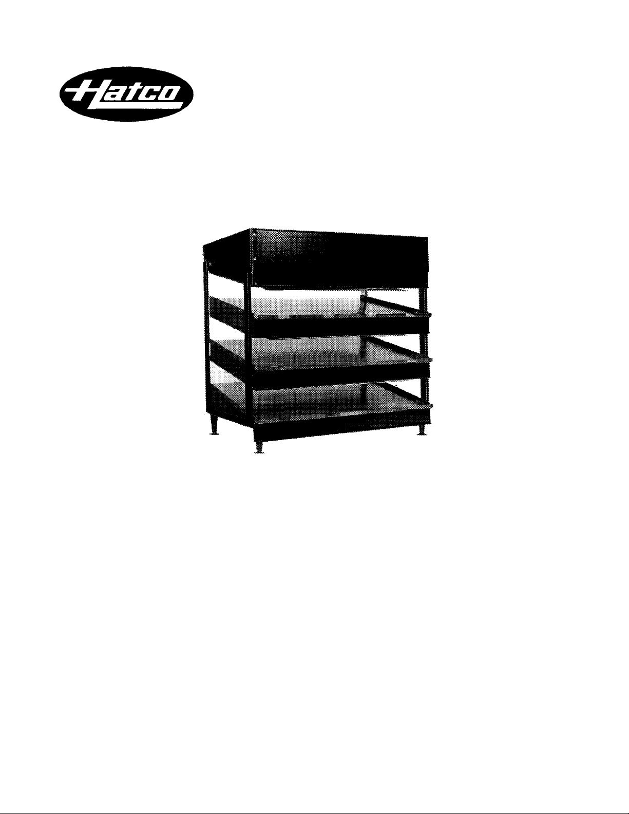
WAWA MERCHANDISING WARMER
Models GRSDSI-30T & GRSDSI-36T
HATCO CORPORATION MILWAUKEE, Wl 53234 U.S.A. (800)558-0607 (414)671-6350
Page 2
INSTALLATION & OPERATION. PROCEDURES Models GRSDSI-30T & GRSDSI-36T
Amp
Installation, maintenance and repair to be performed by qualified service personnel only.
SAFETY PRECAUTIONS
Locate the unit at the proper counter height, in an area that is
convenient for use. The location should be level to prevent the
cabinet or its contents from accidentally falling, and strong
enough to support the weight of the unit and food product
displayed. Place unit a minimum of 1" (3cm) from counter edge
to prevent unit from accidentally falling.
For safe and proper operation, the unit must be located a
reasonable distance from combustible walls and materials. If
safe distances are not maintained, discoloration or combustion
could occur.
Plug unit into an electrical outlet of the correct voltage, size
and plug configuration. If plug and receptacle do not match,
contact a qualified electrician to determine proper voltage and
size and install proper electrical outlet.
To prevent electrical shock, always unplug the unit before
performing cleaning, maintenance or repair.
Some exterior surfaces on the unit will get hot. Use caution
when touching these areas to avoid injury.
This product contains a hard-lube teflon coated surface and is
intended for PACKAGED FOOD CONTACT ONLY.
ELECTRICAL SPECIFICATIONS
Model Voltage Wattage
GRSDSI-30T
GRSDSI-36T
120/208-240 2450 10.3
120/208-240 2865 12.6
Plug Ship
Configuration Weight
NEMA L-14-20P
NEMA L-14-20P
200 Ibs.(91kg)
230lbs.(104kg)
DIME NSIONS
36 3/4" H (with legs attached) x 30" W x 25 1/4”D (93 x 76 x 64 cm)
36 3/4" H(with legs attached) x 36" W x 25 1/4” D (93 x 91 x 64 cm)
INSTALLATION
Safe and proper installation, unpacking and setup of this unit
requires a minimum of two (2) people.
1. Unpack and unwrap all parts.
2. The package includes:
2-Tempered Glass End Panels 1-GRSDSI Warmer
1-Bottom Front Sign Holder 4-Mounting Legs w/Anti
1-Upper Front Sign Holder -Skid Feet
1-Sign Holder Box 2-Side Sign Holders
1-Bag Miscellaneous Hardware
Do not lay unit on its back side (control panel side) or the
front side, damage to the unit could occur.
3. 4" (15 cm) Legs with Anti-Skid Feet: Attach self -adhesive anti-
skid pads to the bottom of each leg. Two people should
carefully tilt the unit on one of its ends and thread two of the
legs into the holes provided. Carefully tilt the warmer to the
other end and thread the two remaining legs into the holes
provided. Tighten until secure. If the unit is not level or rocking
occurs, the adjustable tip of each leg can be turned to correct
the condition.
4. Bottom Shelf Sign Holder (1 piece): Position the sign holder
over the screw holes.
NOTE: The hole-notch opening should be facing up.
Insert screws through the sign holder and fasten securely.
5. Side Sign Holders for Top (2 pieces): To install remove the
four (4) upper end plate screws on each side using a Phillips
screwdriver. With the lip edge facing outward, position the
sign holder(s) over the screw holes. Re-insert the screws
through the sign holder(s) and fasten securely.
NOTE: Install side sign holders before upper front sign holder.
6. Upper Sign Holder for Top (1 piece): With the lip edge facing
outward, position upper front sign holder over the front screw
holes (3 on each side). Secure the sign holder by placing a
screw in each hole through the front and a Keps-Nut on
back. Tighten securely.
7. Box for Signs: To install position the box with the two (2)
slotted screw holes over the two shoulder screws located at
the rear of the unit (right of the master on/off switch).
8. Glass Installation: Position the glass near the end of the unit.
Place one hand on the inside of the warmer against the glass
and the other hand on the outside against the glass.
Carefully lift the glass upward and position into the upper
mounting channel. Gently position bottom edge of the glass
into bottom channel.
OPERATION
To operate warmer, turn the master power switch to the "ON"
position. Each shelf (upper, middle and bottom) can be controlled individually by positioning the corresponding switch to the
"ON" position. Allow 30 minutes for warmer to heat up.
NOTE: Master on/off switch must be in the "ON" position for the
unit to function.
NOTE: This unit is equipped with three (3) dual setpoint controllers
that monitor and regulate the temperature of each shelf. The base
temperature SP1 is factory set at 179° F. (82° C). The upper
temperature SP2 is factory set at 272° F. (133" C).
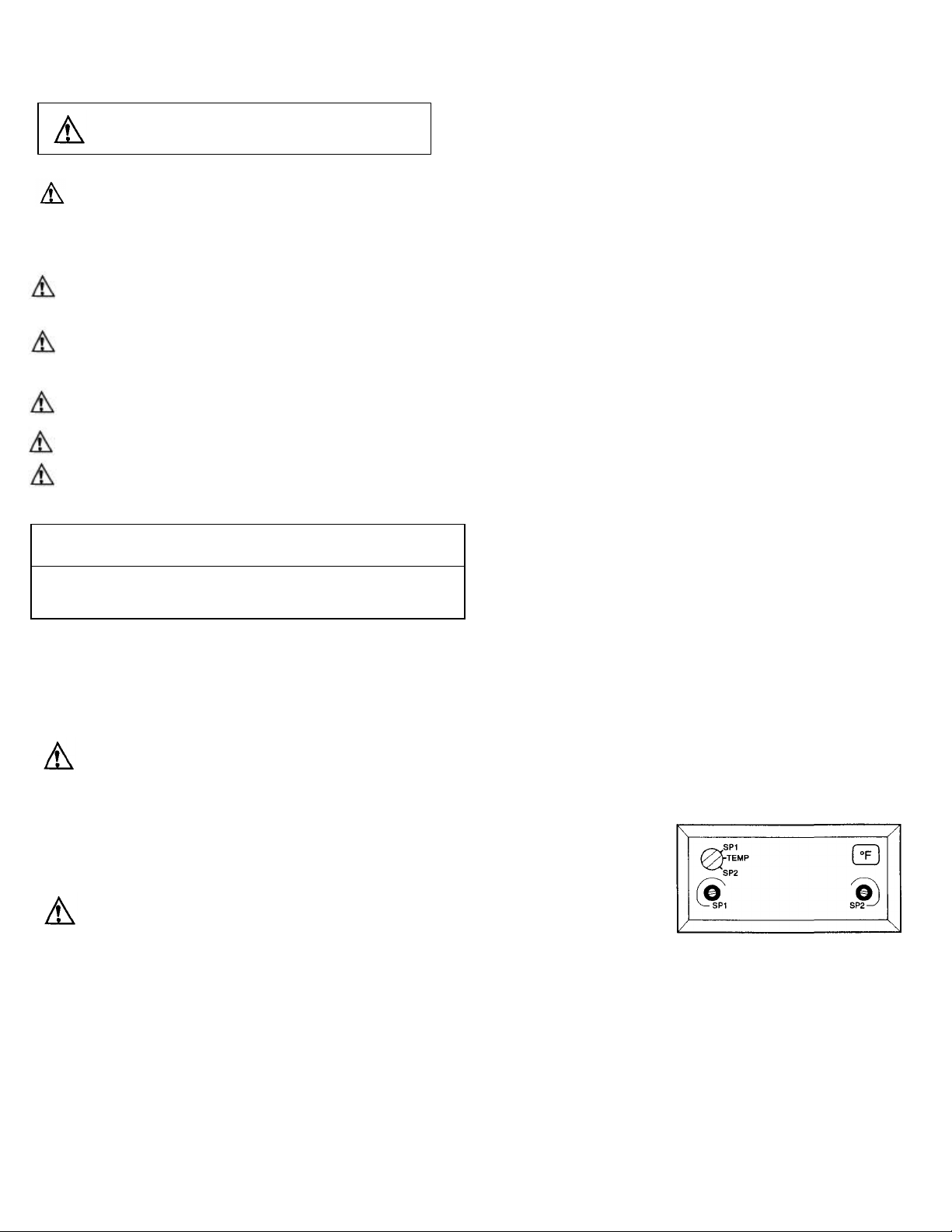
If the temperature controllers) require adjustment, follow these
steps:
1. Remove tamperproof cover using screwdriver.
2. Turn red mode switch to SP1 position for the base temperature and adjust by
turning adjustment
screw to the desired
setting. To adjust the
upper temperature
turn red mode switch
to SP2 position and
adjust screw to
desired setting. When
adjustments are completed, return red mode switch to the
TEMP position and reinstall tamperproof cover over
controllers.
Page 3

MAINTENANCE
1. Master On/Off Toggle Switch
02.19.007.00
1
11. Coated Light Bulb
- 60
Watt 02.30.04
3.00 9 2. On/Off Toggle Switch
-
Shelves
02.19.008A.00
3
12. Light Bulb Socket
- Single
02.30.051.00
3 3.
On/Off Indicator Plate
07.01.058.00
4
13. Light Bulb Socket
- Dual 02.30.047.00
3
5. Dual Control Temp Display
02.01.073.00
3
15. Cord Grip
02.20.226.00
1
7. Temperature Probe
-
Upper
02.01.146.00
3
Protective Wire Guard
(36"
unit) 04.08.178.00
6
9. Blanket Element
18. Rear Sign Box Assembly
04.15.915.00
1
Bottom Shelf
(30"
Unit) 02.05.213.00
1
19. Left Side Sign Holder
04.15.916.00
1
M
iddle Shelf
(30"
Unit) 02.05.214.00
1
20. Right Side Sign Holder
04.15.917.00
1
Upper Shelf
(30"
Unit) 02.05.214.00
1
21. Shelf Sign Holder
(30"
Unit) 04.15.926.00
3
Middle Shelf
(36"
Unit) 02.05.212.00
1
22. Upper Sign Holder
(30"
Unit) 04.15.925:86.
1
Upper Shelf
(36"
Unit) 02.05.212.00
1
Upper Sign Holder
(36"
Unit) 04.15.919.00
1
10. Overhead Heating Element
23. Plastic Legs with Pads
-
4"
Hi
gh 05.30.065.00
4
Infra-Black Assembly
(30"
Unit) R02.08.505.00
6
24. Rubber Pad*
05.30.065A.00
4
The Hatco GRSDSI warmers are designed for maximum durability and performance with minimum maintenance. To avoid
injury, turn the master power switch off, unplug the unit from
power source and allow to cool before performing any maintenance.
CLEANING
To preserve the finish of your unit, it is recommended that the
exterior and interior surfaces be wiped daily with a soft damp
cloth. Stubborn stains may be removed with a NON-ABRA SIVE, MILD CLEANER.
Use only NON-ABRASIVE CLEANERS. Abrasive
cleaners will scratch the hard-lube teflon finish of the
shelves, marring its appearance, making it susceptible to
soil accumulation and reducing the performance.
Clean the glass sides using a common glass cleaner.
To remove the glass sides, turn the unit off and wait until it is
cool. Place one hand on the inside against the glass and the
other hand on the outside against the glass. Lift the glass
REPLACEMENT PARTS LIST
Models GRSDSI-30T & GRSDSI-36T
upward and then outward away from the unit allowing the glass
to be removed from the channel. Reverse this procedure to
reinstall.
DISPLAY LIGHT BULB REPLACEMENT - The display lights
are incandescent 60 watt light bulbs which illuminate the product area. These bulbs have a special coating to guard against
injury and food contamination in the event of breakage.
To replace a light bulb, disconnect the power supply and wait
until the unit has cooled. Unscrew the light bulb from the unit
and replace it with a new specially coated incandescent bulb.
NOTE: Hatco shatter-resistance light bulbs meet N.S.F. standards for
food holding and display areas. For 120 volt applications, use Hatco
part #02.30.043.00.
Only bulbs which meet or exceed N.S.F. standards,
specifically designed for food holding areas may be used.
Breakage of bulbs not specially coated could result in
personal injury and /or food contamination.
Item Description Part No. Qty.
4. Transformer 120-24V 02.17.034.00 1
6. Temperature Probe-Lower 02.01.057.00 3
8. 24 Volt Relay R02.01.050.00 6
Bottom Shelf (36" Unit) 02.05.211.00 1
Infra-Black Assembly (36" Unit) R02.08.508.00 6
* Not shown.
Item Description Part No. Qty.
14. Power Cord with Plug 02.18.128.00 1
16. Protective Wire Guard (30" unit) 04.08.419.00 6
17. Glass End Panels 04.40.090.00 2
Shelf Sign Holder (36" Unit) 04.15.918.00 3
Page 4

P.O. Box 340500, Milwaukee, WI 53234-0500 U.S.A.
(800)558-0607 (414)671-6350 Parts & Service Fax (800) 690-2966 Int'l. Fax (414) 671-3976
HATCO CORPORATION
Web Site: www.hatcocorp.com
Printed in U.S.A. Form No. QRSDSIM -0298
 Loading...