

Page 1
WARNING
ADVERTENCIA
AVERTISSEMENT
Register Online!
hatcocorp.com
(see page 2)
S'inscrire en ligne!
(voir page 20)
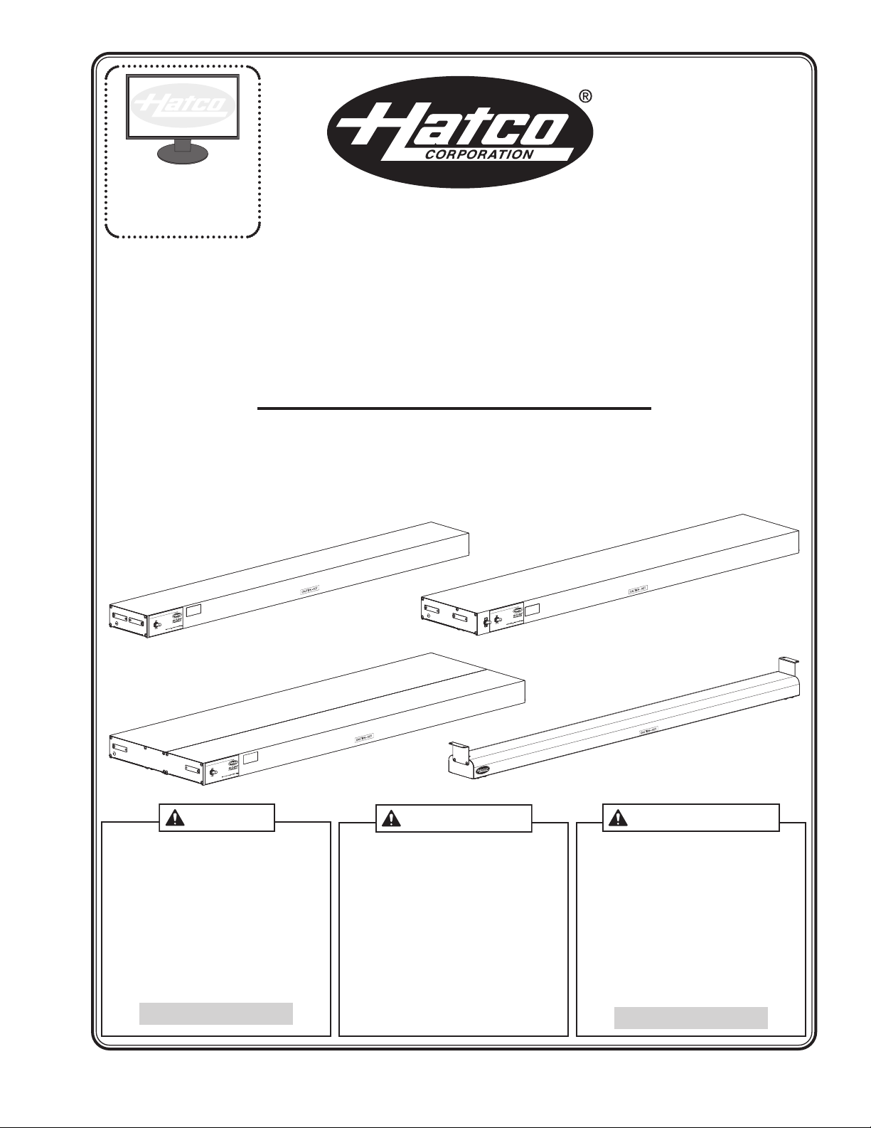
GLO-RAY
®
Infrared Strip Heaters
Rampes Chauffantes à Infrarouge
GR, GRH, GRL, GRHL, GRA, GRAH, GRAL,
GRAHL, GRN, GRNH Series/Série
Installation and Operating Manual
Manuel d'installation et d'utilisation
P/N 07.04.413.00
Do not operate this equipment unless you
have read and understood the contents of
this manual! Failure to follow the
instructions contained in this manual may
result in serious injury or death. This
manual contains important safety
information concerning the maintenance,
use, and operation of this product. If
you’re unable to understand the contents
of this manual, please bring it to the
attention of your supervisor. Keep this
manual in a safe location for future
reference.
English = p 2
No opere este equipo al menos que haya
leído y comprendido el contenido de este
manual! Cualquier falla en el seguimiento
de las instrucciones contenidas en este
manual puede resultar en un serio lesión
o muerte. Este manual contiene
importante información sobre seguridad
concerniente al mantenimiento, uso y
operación de este producto. Si usted no
puede entender el contenido de este
manual por favor pregunte a su
supervisor. Almacenar este manual en
una localización segura para la referencia
futura.
Ne pas utiliser cet équipement sans avoir
lu et compris le contenu de ce manuel !
Le non-respect des instructions
contenues dans ce manuel peut entraîner
de graves blessures ou la mort. Ce
manuel contient des informations
importantes concernant l'entretien,
l'utilisation et le fonctionnement de ce
produit. Si vous ne comprenez pas le
contenu de ce manuel, veuillez le signaler
à votre supérieur. Conservez ce manuel
dans un endroit sûr pour pouvoir vous y
référer plus tard.
Français = p 20
© 2015 Hatco Corporation
Page 2
NOTICE
CAUTION
WARNING
24 Hour 7 Day Parts and Service
Assistance available in the United States
and Canada by calling 800-558-0607.
CONTENTS
English
Important Owner Information ..............................................2
Introduction...........................................................................2
Important Safety Information...............................................3
Model Description.................................................................4
Model Designation................................................................4
Specifications........................................................................5
Plug Configurations ............................................................5
Dimensions.........................................................................5
Installation.............................................................................6
General...............................................................................6
Recommended Mounting Heights ......................................7
Minimum Clearance Requirements for Combustible
Surroundings.....................................................................7
Minimum Clearance Requirements for
Non-Combustible Surroundings........................................8
IMPORTANT OWNER INFORMATION
Record the model number, serial number, voltage, and
purchase date of your strip heater in the spaces below
(specification label located on the underside of the unit). Please
have this information available when calling Hatco for service
assistance.
Model No. ________________________________________
Serial No. ________________________________________
Voltage __________________________________________
Date of Purchase __________________________________
Installing Portable Units......................................................9
Installing Chain Suspended Units ....................................10
Installing Permanent Units................................................11
Electrical Information........................................................13
Operation.............................................................................14
General.............................................................................14
Maintenance ........................................................................15
Cleaning ...........................................................................15
Replacing Display Light Bulbs..........................................15
Troubleshooting Guide ......................................................16
Options and Accessories...................................................16
Limited Warranty.................................................................19
Authorized Parts Distributors............................Back Cover
Business
Hours: 8:00
Telephone: 800-558-0607; 414-671-6350
E-mail: partsandservice@hatcocorp.com
Fax: 800-690-2966 (Parts and Service)
AM to 5:00 PM Central Standard Time (CST)
(Summer Hours: June to September—
8:00
AM to 5:00 PM CST Monday–Thursday
8:00
AM to 2:30 PM CST Friday)
414-671-3976 (International)
Register your unit!
Completing online warranty registration will prevent delay in
obtaining warranty coverage. Access the Hatco website at
www.hatcocorp.com, select the Parts & Service pull-down
menu, and click on “Warranty Registration”.
INTRODUCTION
Hatco Glo-Ray®Infrared Strip Heaters ensure maximum food
holding and minimize the risk of food-borne illness. Optimum
safety and quality is the result of food held at the proper serving
temperatures using Glo-Ray’s pre-focused heat patterns. The
pre-focused heat pattern prevents foods from being overcooked in the middle and cooling off around the edges by
concentrating higher temperatures to the outer edges of holding
surfaces where heat loss is the greatest. Utilizing specially
designed reflectors to direct the heat from the element, GloRay Strip Heaters safely maintain peak serving temperatures
longer without cooking the food beyond the point of excellence.
Glo-Ray Infrared Strip Heaters are available from the factory
with or without shatter-resistant incandescent lights to illuminate
the warming area. These bulbs have a special coating that
guards against injury and food contamination in the event of
breakage.
Glo-Ray Infrared Strip Heaters are a product of extensive
research and field testing. The materials used were selected
for maximum durability, attractive appearance, and optimum
performance. Every unit is inspected and tested thoroughly
prior to shipment.
Additional information can be found by visiting our web site at
www.hatcocorp.com.
This manual provides the installation, safety, and operating
instructions for Glo-Ray Infrared Strip Heaters. Hatco
recommends all installation, operating, and safety instructions
appearing in this manual be read prior to installation or
operation of the Strip Heaters.
Safety information that appears in this manual is identified by
the following signal word panels:
WARNING indicates a hazardous situation which, if not
avoided, could result in death or serious injury.
CAUTION indicates a hazardous situation which, if not
avoided, could result in minor or moderate injury.
NOTICE is used to address practices not related to
personal injury.
2
Form No. GRM-0115
Page 3
English
WARNING
CAUTION
NOTICE
WARNING
IMPORTANT SAFETY INFORMATION
Read the following important safety information before using this equipment to avoid serious
injury or death and to avoid damage to equipment or property.
ELECTRIC SHOCK HAZARD:
• Units supplied without an electrical plug require a hardwired
connection to on-site electrical system. Connection must be
properly grounded and of correct voltage, size, and
configuration for electrical specifications of unit. Contact a
qualified electrician to determine and perform proper electrical
connection.
• Plug unit into a properly grounded electrical receptacle of the
correct voltage, size, and plug configuration. If plug and
receptacle do not match, contact a qualified electrician to
determine and install proper voltage and size electrical
receptacle.
• Turn OFF power switch, unplug power cord/turn off power at
circuit breaker, and allow unit to cool before performing any
cleaning, adjustments, or maintenance.
• DO NOT submerge or saturate with water. Unit is not
waterproof. Do not operate if unit has been submerged or
saturated with water.
• This unit is not “jet-proof” construction. Do not use jet-clean
spray to clean this unit.
• Do not steam clean or use excessive water on unit.
• Discontinue use if power cord is frayed or worn.
• Do not attempt to repair or replace a damaged power cord.
The cord must be replaced by Hatco, an Authorized Hatco
Service Agent, or a person with similar qualifications.
• Use only Genuine Hatco Replacement Parts when service is
required. Failure to use Genuine Hatco Replacement Parts will
void all warranties and may subject operators of the
equipment to hazardous electrical voltage, resulting in
electrical shock or burn. Genuine Hatco Replacement Parts
are specified to operate safely in the environments in which
they are used. Some aftermarket or generic replacement parts
do not have the characteristics that will allow them to operate
safely in Hatco equipment.
FIRE HAZARD:
• Locate unit the correct distance from combustible walls and
materials. If safe distances are not maintained, discoloration
or combustion could occur. Refer to specific installation and
mounting information in this manual for proper clearances.
• Make sure to follow the installation information listed below for
specific strip heaters. If safe distances are not maintained,
discoloration or combustion could occur.
a. Do not install standard wattage strip heaters (GR, GRA,
GRN, GRL, and GRAL Series) less than 10″ (254 mm) above
combustible surfaces.
b. Do not install high wattage strip heaters (GRH, GRHL,
GRAH, GRNH, GRAHL Series) less than 13-1/2″ (343 mm)
above combustible surfaces.
c. Do not install dual strip heaters above combustible surfaces.
e. Install all single strip heaters with a minimum distance of 3″
(76 mm) from a combustible wall or adjacent surface.
EXPLOSION HAZARD: Do not store or use gasoline or other
flammable vapors or liquids in the vicinity of this or any other
appliance.
Use only light bulbs that meet or exceed National Sanitation
Foundation (NSF) standards and are specifically designed for food
holding areas. Breakage of light bulbs not specially coated could
result in personal injury and/or food contamination.
This unit is not intended for use by children or persons with
reduced physical, sensory, or mental capabilities. Ensure proper
supervision of children and keep them away from the unit.
Make sure all operators have been instructed on the safe and
proper use of the unit.
Make sure food product has been heated to the proper food-safe
temperature before placing in unit. Failure to heat food product
properly may result in serious health risks. This unit is for holding
pre-heated food product only.
For installation with chains, make sure the chains have sufficient
strength and are securely fastened to both the unit and the mounting
location. Poorly installed chains may cause the unit to loosen and
fall. Do not place anything on top of units installed with chains.
This unit has no “user-serviceable” parts. If service is required on
this unit, contact an Authorized Hatco Service Agent or contact
the Hatco Service Department at 800-558-0607 or 414-671-6350;
fax 800-690-2966; or International fax 414-671-3976.
BURN HAZARD: Some exterior surfaces on the unit will get hot.
Use caution when touching these areas.
Standard and approved manufacturing oils may smoke up to 30
minutes during initial startup. This is a temporary condition.
Operate unit without food product until smoke dissipates.
Strip heaters equipped with incandescent lights that require a
circuit breaker larger than 20 amps for the heat element must have
a separate circuit breaker for the incandescent lights that is 20
amps or less.
To ensure safe and proper operation, refer to the Clearance
Requirements listed in the Installation section of this manual.
Installation of two or more separate units with less than
3″ (76 mm) between housings may result in premature failure of
component parts. Failure to provide proper spacing may result in
heat damage to electrical components.
Units are voltage-specific. Refer to specification label for electrical
requirements before beginning installation.
Do not add a decorative soffit to hide a pass-through mounted strip
heater. Excessive heat can cause unit failure.
To prevent premature failure of components due to excessive
heat, remote mounted control switches must be installed outside
the strip heater heat zone.
Damage to any countertop material caused by heat generated
from Hatco equipment is not covered under the Hatco warranty.
Contact the manufacturer of the countertop material for
application information.
Use non-abrasive cleaners and cloths only. Abrasive cleaners and
cloths could scratch the finish of the unit, marring its appearance
and making it susceptible to soil accumulation.
IMPORTANT—DO NOT use paper towel or glass cleaner to clean
plastic surfaces. Paper towel and glass cleaner may scratch the
material. Wipe off plastic surfaces using a soft, clean, waterdampened cloth.
Do not locate unit in area with excessive air movement around
unit. Avoid areas that may be subject to active air movements or
currents (i.e., near exhaust fans/hoods, air conditioning ducts, and
exterior doors).
Form No. GRM-0115
3
Page 4
MODEL DESCRIPTION
G R A H L - XX D
Glo-Ray
Housing Type:
A = Aluminum
N = Narrow Powder-Coated Steel
No Character = Stainless Steel Housing
L = Incandescent Light
No Character = Without Lights
D = Dual Elements
No Character = Single Element
Width (in inches)
H = High Wattage
No Character = Standard Wattage
All Models
Hatco Glo-Ray®Infrared Strip Heaters keep hot foods at
optimum serving temperatures longer. Foods do not dry out or
become discolored; even the most delicate dishes hold that “justprepared” look. The Glo-Ray pre-focused heat pattern directs
heat from a tubular element to bathe the entire holding surface.
Glo-Ray strip heaters can be ordered in standard or high
wattage configurations, stainless steel housings in lengths of
24″–96″ (610 mm–2438 mm), aluminum housings in lengths of
18″–144″ (457–3658 mm), or narrow design housings in lengths
of 18″–72″ (457–1829 mm).
All strip heaters have several mounting options and switch
locations. Optional infinite control switches, remote control
enclosures, incandescent lighting, and sneeze guards are
available also.
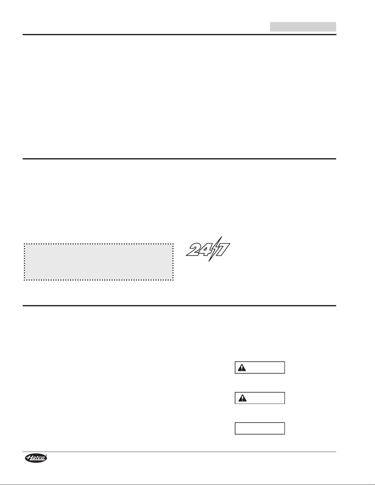
GR-XX, GRH-XX, GRL-XX, and GRHL-XX
Models
Stainless steel models are available with or without
incandescent lights
NOTE: Stainless steel strip heaters are not available with
sneeze guards.
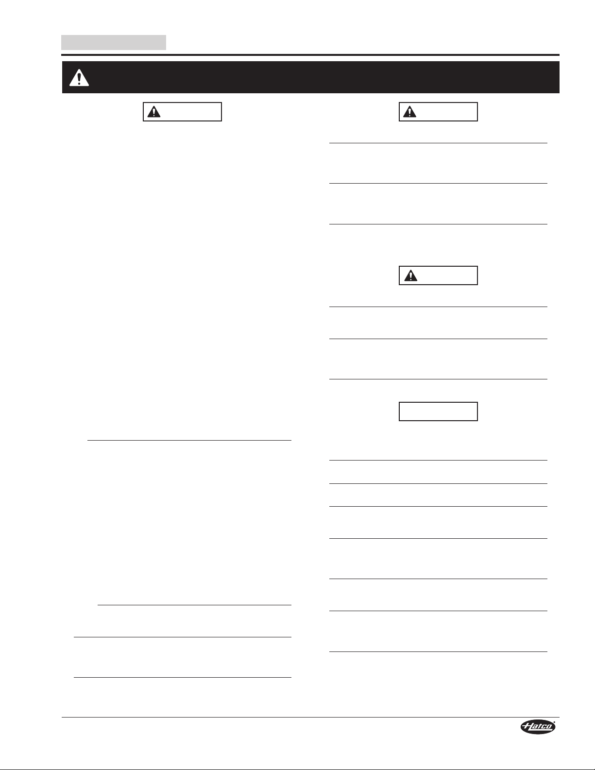
GRA-XX, GRAH-XX, GRAL-XX, and
GRAHL-XX Models
Aluminum, single element models are available either with or
without incandescent lights or sneeze guards.
English
GRA-48 Model
GRAHL-48 Model
GR-XXD, GRA-XXD, GRH-XXD, GRAH-XXD,
GRL-XXD, GRAL-XXD, GRHL-XXD, and
GRAHL-XXD Models
Dual models allow for side-by-side mounting of two or more strip
heaters to provide a wider holding area. Dual models are
constructed with a required 3″ (76 mm) or 6″ (152 mm) spacer
between heating elements.
Dual models are available either with or without incandescent
lights or sneeze guards (sneeze guards not available for
stainless steel models).
NOTE: Incandescent lights and sneeze guards are not
available for retrofit.
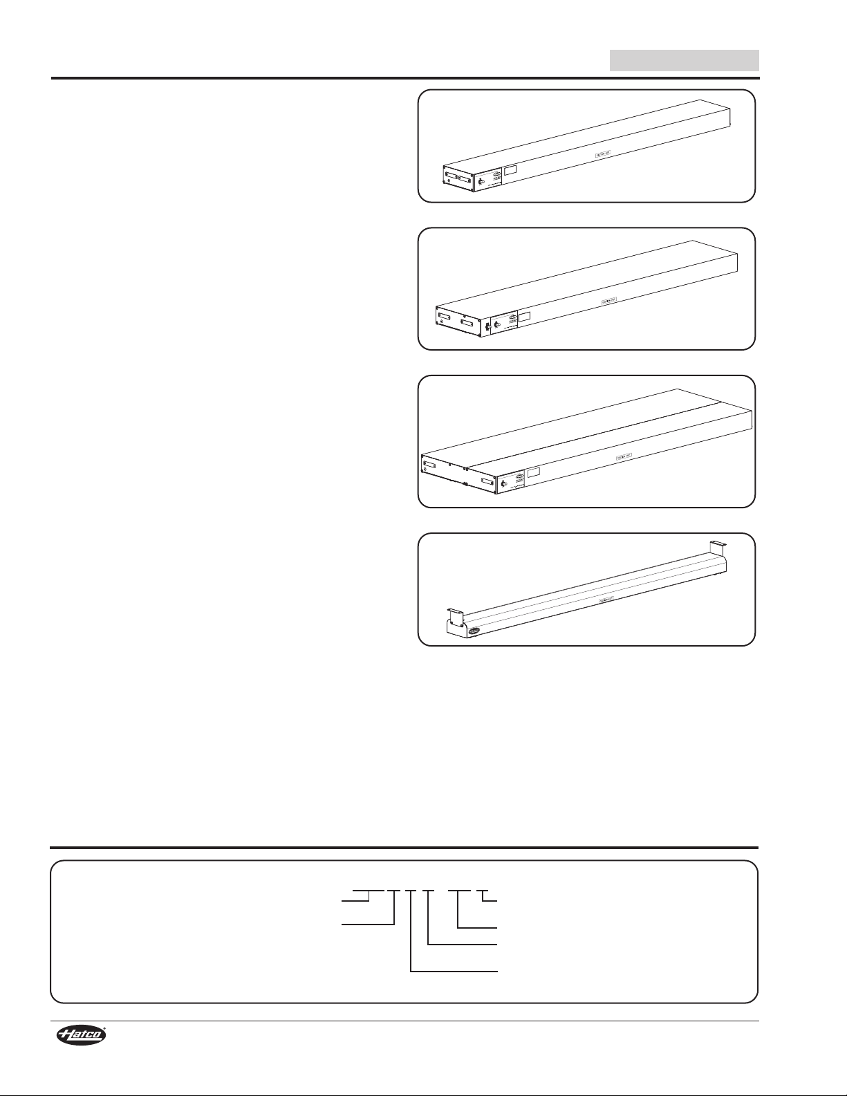
GRN-XX and GRNH-XX Models
Narrow models are available in stainless steel or powdercoated
steel in several Designer colors.
NOTE: Narrow design strip heaters are not available with lights,
sneeze guards, or as dual units.
MODEL DESIGNATION
GRAL-48D Model
GRN-48 Model
4
Form No. GRM-0115
Page 5
English
Single Element Models
(Shown with Optional Sneeze Guards)
A
D
C
B
A
B
C
A
D
C
B
Narrow Models
E
E
NOTE: Add 8-1/2" (216 mm) to Depth (D) and
1-3/4" (44 mm) to Height (E) if unit is
configured with an optional 14" (356 mm)
sneeze guard.
Dual Element Models
(Shown with Optional 9-3/8" Sneeze Guards)
WARNING
NEMA 5-15P
NEMA 5-20P
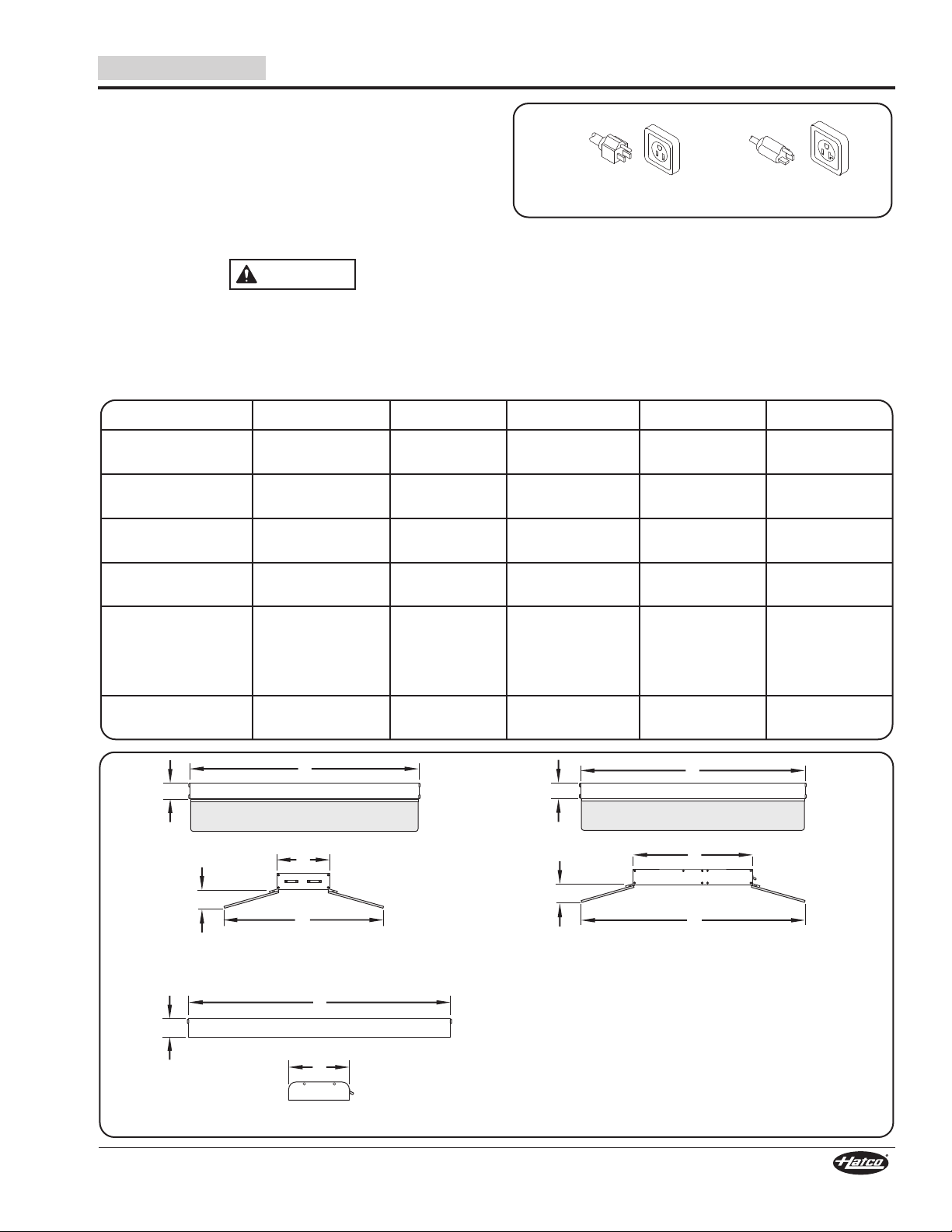
Plug Configurations
An attached 6’ (1829 mm) cord and plug is available as a
factory-installed option for certain units. These units must be
120 V (volt) models with built-in controls that are 72″ (1829 mm)
in width or less and mounted with a standard chain kit, C-leg
stand, or T-leg stand.
NOTE: Cord and plug configurations are not available for units
with adjustable tubular stands or non-adjustable tubular
stands.
ELECTRIC SHOCK HAZARD: Plug unit into a properly
grounded electrical receptacle of the correct voltage, size,
and plug configuration. If plug and receptacle do not
match, contact a qualified electrician to determine and
install proper voltage and size electrical receptacle.
Dimensions
Model Width (A) Height (B) Depth (C) Depth (D) Height (E)
SPECIFICATIONS
Plug Configuration
NOTE: Receptacle not supplied by Hatco.
NOTE: Refer to the wiring diagram supplied with the unit and
specification label attached to the unit for specific
electrical information. Also, refer to the “Electrical Rating
Charts” document on the Infrared Strip Heaters page of
the Hatco website (www.hatcocorp.com).
GR and GRH
GRA and GRAH
GRAL and GRAHL
GRL and GRHL
GR-, GRA-,
GRH-, GRAH-,
GRL-, GRAL-,
GRHL-, and
GRAHL-XXD
GRN and GRNH
18″–96″
(457–2438 mm)
18″–144″
(457–3658 mm)
18″–144″
(457–3658 mm)
18″–72″
(457–1829 mm)
18″–144″
(457–3658 mm)
18″–72″
(457–1829 mm)
2-1/2″
(63 mm)
2-1/2″
(63 mm)
2-1/2″
(63 mm)
2-1/2″
(63 mm)
2-1/2″
(63 mm)
2″
(51 mm)
6″
(152 mm)
6″
(152 mm)
9″
(229 mm)
9″
(229 mm)
3″ spacer:
15″ (381 mm)
6″ spacer:
18″ (457 mm)
4″
(102 mm)
--- ---
23″
(584 mm)
26″
(660 mm)
26″
(660 mm)
3″ spacer:
32″ (813 mm)
6″ spacer:
35″ (889 mm)
--- ---
4″
(102 mm)
4″
(102 mm)
4″
(102 mm)
4″
(102 mm)
Form No. GRM-0115
5
Page 6
INSTALLATION
WARNING
CAUTION
NOTICE
NOTICE
English
General
Use the information in this section to prepare for and install a
Glo-Ray
information in this section for the type of installation. Strip
heaters are shipped with most components pre-assembled.
Dual units are supplied with a required 3″ (76 mm) or
6″ (152 mm) spacer pre-assembled at the factory.
FIRE HAZARD:
To ensure safe and proper operation, refer to the Clearance
Requirements listed in the Installation section of this
manual.
Units are voltage-specific. Refer to specification label for
electrical requirements before beginning installation.
Do not add a decorative soffit to hide a pass-through
mounted strip heater. Excessive heat can cause unit
failure.
Damage to any countertop material caused by heat
generated from Hatco equipment is not covered under the
Hatco warranty. Contact the manufacturer of the
countertop material for application information.
NOTE: Contact the manufacturer of the countertop base
NOTE: To prevent delay in obtaining warranty coverage,
NOTE: If the unit is configured with optional equipment, see the
®
Infrared Strip Heater. Make sure to locate the specific
• Locate the unit the correct distance from combustible
walls and materials. If safe distances are not
maintained, discoloration or combustion could occur.
Refer to specific installation and mounting information
in this manual for proper clearances.
• Make sure to follow the installation information listed
below for specific strip heaters. If safe distances are not
maintained, discoloration or combustion could occur.
a. Do not install standard wattage strip heaters (GR,
GRA, GRN, GRL, and GRAL Series) less than 10″
(254 mm) above combustible surfaces.
b. Do not install high wattage strip heaters (GRH,
GRHL, GRAH, GRNH, GRAHL Series) less than
13-1/2″ (343 mm) above combustible surfaces.
c. Do not install dual strip heaters above combustible
surfaces.
e. Install all single strip heaters with a minimum
distance of 3″ (76 mm) from a combustible wall or
adjacent surface.
material for application information and surface
temperature limits before installing the unit.
1. Remove the unit from the shipping carton and remove all
packing materials.
complete online warranty registration. See the
IMPORTANT OWNER INFORMATION section for
details.
2. Remove tape and protective packaging from all surfaces
of the unit.
OPTIONSANDACCESSORIES section in this manual.
3. Install/mount the unit in an appropriate location.
a. Verify recommended mounting heights and minimum
clearance requirements are met for the appropriate
model. Refer to “Recommended Mounting Heights” and
“Minimum Clearance Requirements” in this section.
b. For portable unit installation, refer to “Installing Portable
Units” in this section.
c. For chain suspension installation, refer to “Installing
Chain Suspended Units” in this section.
d. For permanent unit installation, refer to “Installing
Permanent Units” in this section.
Dual Mounting
When mounting units side-by-side, a space not less than 3″
(76 mm) must be maintained between units. Dual units ordered
from the factory are shipped with a pre-assembled 3″ (76 mm)
or 6″ (152 mm) spacer.
NOTE: Dual units are available with aluminum housings only.
Installation of two or more separate units with less than 3″
(76 mm) between housings may result in premature failure
of component parts. Failure to provide proper spacing may
result in heat damage to electrical components.
Under Shelf Mounting
When mounting a unit under a shelf, use adjustable angle
brackets to assure proper spacing. Remote control enclosures
are recommended to keep switches out of the heat zone and
prevent premature failure.
Pass-Through
If a pass-through area is 12″–16″ (305–406 mm) deep, a
standard wattage or high wattage single unit can be used. For
a 20″–24″ (508–610 mm) deep pass-through area, a dual unit
in either standard or high wattage is recommended. Installation
of multiple units must have a minimum spacing of 3″ (76 mm)
between heaters.
T-Legs or C-Legs
Units must be 120 V and be equipped with a cord and plug. Do
not mount units longer than 72″ (1829 mm) on T-legs or C-legs.
Over Steam Table
When mounting over a steam table, a remote control enclosure
must be installed.
6
Form No. GRM-0115
Page 7
English
A
B
C
Shelf
Back Wall
Counter
4″–6″
(102–152 mm)
12″ (305 mm)
8″–11″
(203–279 mm)
Standard Wattage
Height
High Wattage
Height
11″–14″
(279–356 mm)
Add 3″ for
units with lights.
15″ (381 mm)
21″ (533 mm)
14″–18″
(356–457 mm)
10″–14″
(254–356 mm)
Standard Wattage
Height
High Wattage
Height
10″–14″
(254–356 mm)
Standard Wattage
Height
14″–18″
(356–457 mm)
18″ (457 mm)
24″ (610 mm)
High Wattage
Height
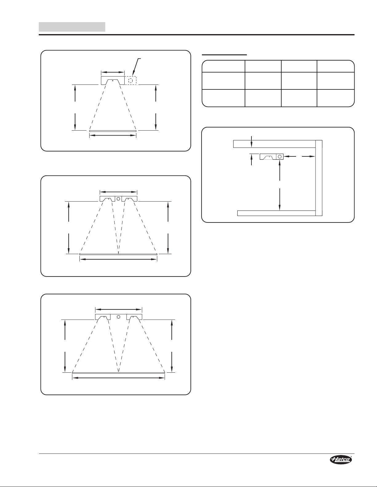
INSTALLATION
Recommended Mounting Heights
Recommended Element Height for the
GR, GRA, GRL, GRH, GRHL, GRN, GRAH, GRAL, GRNH, and
GRAHL models in all lengths (excluding dual models).
Minimum Clearance Requirements for
Combustible Surroundings
Models (A) (B) (C)
GRA and
GRAL
GRAH and
GRAHL
NOTE: Dual strip heaters cannot be installed in
combustible surroundings.
10″
(254 mm)
13-1/2″
(343 mm)
3″
(76 mm)
3″
(76 mm)
1″
(25 mm)
1″
(25 mm)
Recommended Element Height for dual models
Recommended Element Height for dual models
with a 6″ (152 mm) spacer in all lengths.
with a 3″ (76 mm) spacer in all lengths.
Combustible Clearance Requirements
NOTE: The size of heat patterns vary depending on the height
of the unit.
Form No. GRM-0115
7
Page 8
INSTALLATION
C
Shelf
Back Wall
Counter
A
B
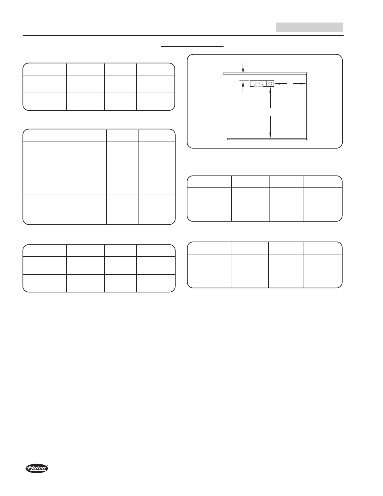
Minimum Clearance Requirements for Non-Combustible Surroundings
Corded Units with Built-In Switches
Models (A) (B)* (C)
English
GRA and
GRAL
GRAH and
GRAHL
10″
(254 mm)
11″
(279 mm)
---
---
Hardwired Units with Built-In Switches
Models
GRA and
GRAL
GRAH and
GRAHL
with Infinite
Control or
Indicator Light
GRAH and
GRAHL
with ON/OFF
Toggle Switch
(A) (B)* (C)
8″
(203 mm)
10″
(254 mm)
8″
(203 mm)
---
---
---
Hardwired Units with Remote Switches
Models (A) (B) (C)
GRA and
GRAL
GRAH and
GRAHL
8″
(203 mm)
8″
(203 mm)
0″
(0 mm)
0″
(0 mm)
3″
(76 mm)
3″
(76 mm)
1″
(25 mm)
1″
(25 mm)
1″
(25 mm)
0″
(0 mm)
0″
(0 mm)
Non-Combustible Clearance Requirements
Dual Units with Built-In Switches
Models (A) (B)* (C)
GRA-XXD
GRAH-XXD
GRAL-XXD
GRAHL-XXD
10″
(203 mm)
---
1″
(25 mm)
Dual Units with Remote Switches
Models (A) (B) (C)
GRA-XXD
GRAH-XXD
GRAL-XXD
GRAHL-XXD
8″
(203 mm)
3″
(76 mm)
0″
(0 mm)
* Must be a pass-through application—not allowed with back
wall installation.
8
Form No. GRM-0115
Page 9
English
CL-Low CL-High
11-1/8″
(283 mm)
12-1/4″
(311 mm)
Removed
Hanger Tabs
C-Leg
Hanger Tab
Screw
End Plate
Screw
12″
(305 mm)
Removed
Hanger Tabs
T-Leg
Hanger Tab
Screw
End Cover
Screw
Mounting
Bracket
INSTALLATION
Installing Portable Units
Single strip heaters under 6′ (1829 mm) long can be mounted on
C-Leg or T-Leg stands for portable use. Portable units are
available in 120 V only and are required to have a power cord
and plug connection.
NOTE: C-Legs and T-Legs are not to be used with dual strip
heater units.
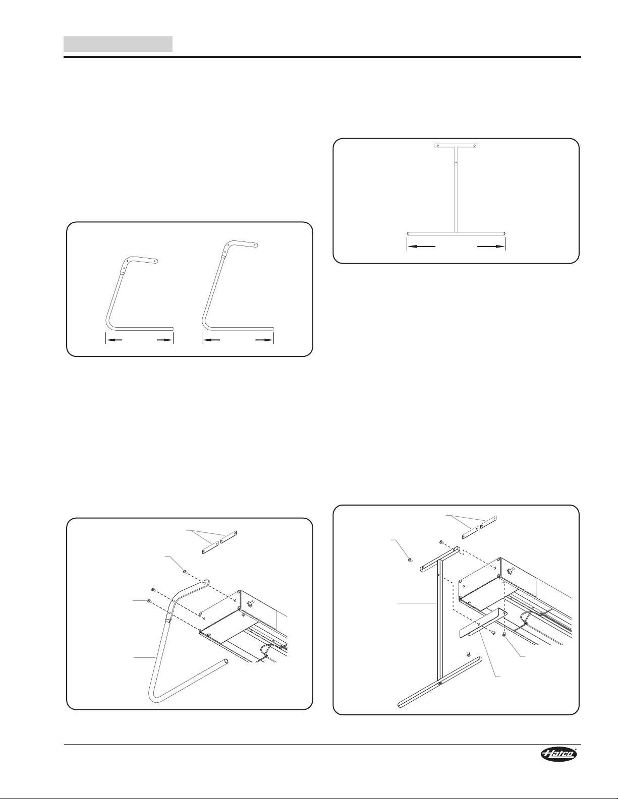
C-Leg Stand Mounting
Two types of C-Legs are available.
• CL-Low = 10″ (254 mm) height, for standard wattage
strip heaters up to 6′ (1829 mm) in width only.
• CL-High = 13-1/2″ (343 mm) height, for high wattage
strip heaters up to 6′ (1829 mm) in width only.
C-Leg Footprint Dimensions
Perform the following procedure to install a C-Leg stand on
each end of the unit.
1. Position the unit upside-down on a flat surface.
2. Install sneeze guard(s), if applicable (refer to the
OPTIONSAND ACCESSORIES section for details on
installing a sneeze guard).
3. Remove the two hanger tab screws and hanger tabs.
4. Remove the one lower end plate screw that aligns with the
lowest mounting hole on the C-Leg.
5. Align the three mounting holes on the C-Leg with the three
holes on the unit. Secure the leg to the unit with the three
screws removed in the previous steps.
T-Leg Stand Mounting
T-Leg stands are available in the following heights:
• Standard wattage units = 10″ (254 mm)
• High wattage units = 13-1/2″ (343 mm)
16″ (406 mm)
18″ (457 mm).
T-Leg Footprint Dimension
Perform the following procedure to install a T-Leg stand on each
end of the unit.
1. Position the unit upside-down on a flat surface.
2. Install sneeze guard(s), if applicable (refer to the
OPTIONSAND ACCESSORIES section for details on
installing a sneeze guard).
3. Align the mounting bracket with the end cover on the
underside of the unit, and remove the two screws on the
end cover that match up with the holes on the mounting
bracket.
4. Secure the mounting bracket to the unit with the two end
cover screws.
5. Remove the two hanger tab screws and hanger tabs.
6. Align the two mounting holes on the small “T” of the T-Leg
with the two hanger tab holes on the end of the unit. Secure
the leg to the unit with the hanger tab screws.
7. Align the single mounting hole on the vertical post of the TLeg with the hole on the mounting bracket. Secure from
the inside with the supplied screw.
Form No. GRM-0115
C-Leg Stand Mounting
T-Leg Stand Mounting
9
Page 10
INSTALLATION
CAUTION
Mounting Hole Distance =
Width (A) – 2-7/16″ (62 mm)
A
1-3/16″
(30 mm)
WARNING
“S” Hook
Connecting Chain
Hanger Ta b
Screw
Overhead Mounting
System
English
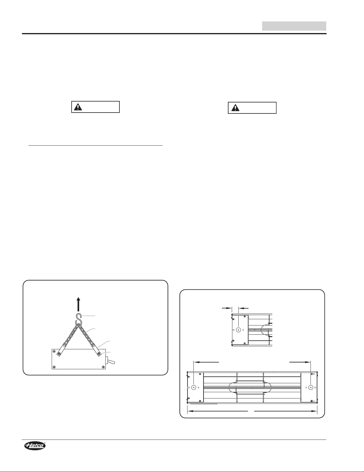
Installing Chain Suspended Units
Chain suspension mounting attaches a strip heater to an
overhead surface with the use of “S” hooks.
NOTE: Units ordered with the “S” hook option come with two
“S” hooks and two 6″ (152 mm) pieces of connecting
chain. Additional chain (P/N 05.03.020.00) can be
ordered from Hatco for the overhead mounting system
or another option can be determined by a qualified
installer.
For installation with chains, make sure the chains have
sufficient strength and are securely fastened to both the
unit and the mounting location. Poorly installed chains may
cause the unit to loosen and fall. Do not place anything on
top of units installed with chains.
To ensure safe and proper operation, refer to the Clearance
Requirements listed in the Installation section of this
manual.
NOTE: The strength of the chain supplied by Hatco is sufficient
to hold the weight of the unit securely only when
mounted properly.
1. Prepare the overhead mounting system for the “S” hooks.
Make sure the system is secure and is set up so the unit
will be suspended at a level, safe, and proper distance from
walls, counter, and food.
2. Loosen, but do not remove the screws securing the hanger
tabs on each end of the unit. Rotate the tabs up, then
tighten the screws securely.
3. Securely attach one of the 6″ (152 mm) connecting chains
between each pair of hanger tabs.
4. Attach an “S” hook to the center of each connecting chain.
5. Carefully lift the unit and attach the “S” hooks on each end
of the unit to the overhead mounting system. Make sure
the unit is level.
Installing Permanent Units
Strip heaters can be mounted permanently with tubular stands
or angle brackets. Permanent units are not available with a
power cord and plug connection. Refer to the proper permanent
mounting section for the installation procedure.
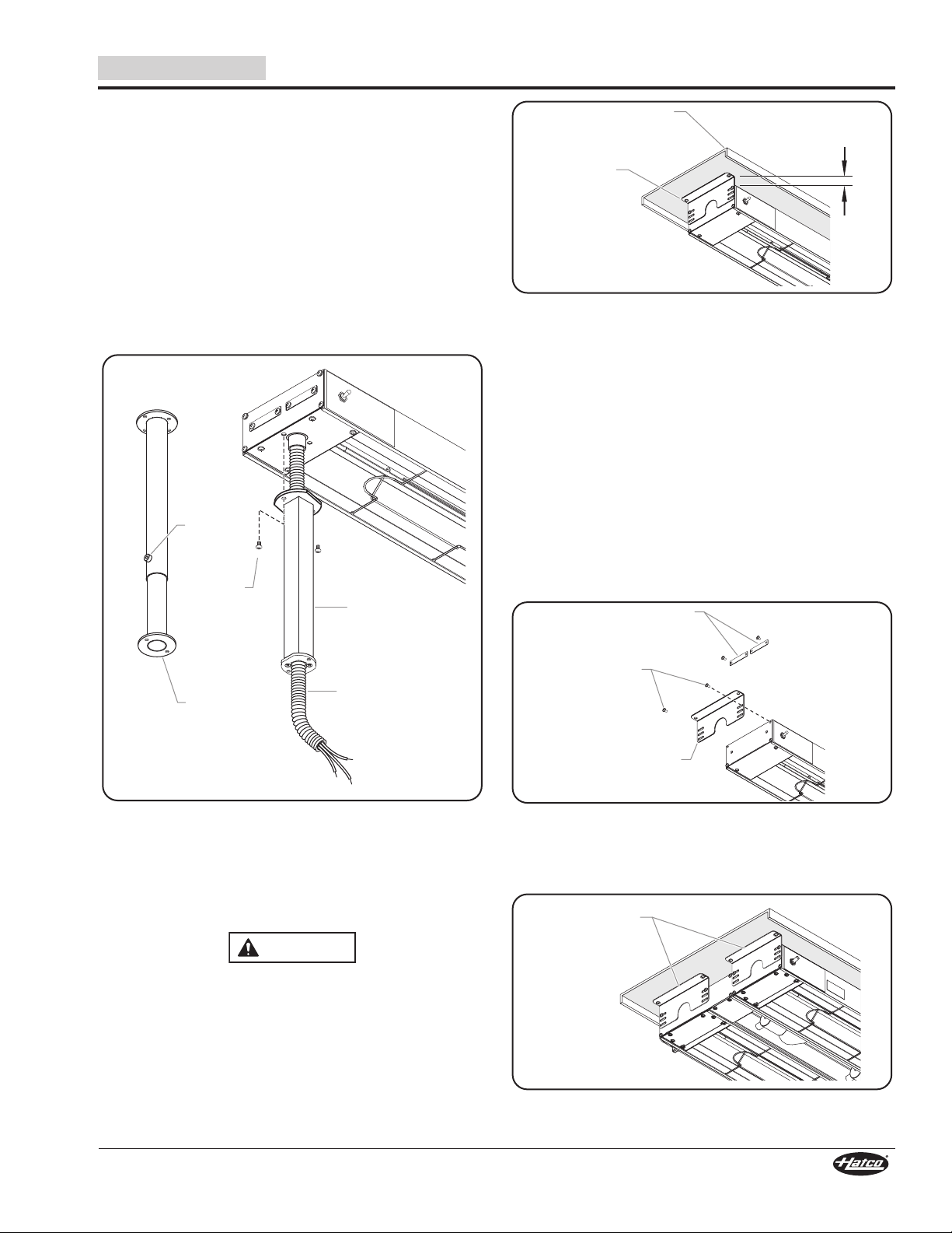
Tubular Stand Mounting
Tubular stand mounting permanently attaches the unit to a
countertop or serving table. All wiring may be concealed within
one of the tubular stands.
To ensure safe and proper operation, refer to the Clearance
Requirements listed in the INSTALLATION section of this
manual.
Non-adjustable tubular stands are available in aluminum,
Designer colors, or gloss finishes in heights from 10″–16″
(254–406 mm). Adjustable tubular stands are available in
stainless steel in heights from 10″–14″ (254–356 mm).
NOTE: Tubular stands are not field retrofittable.
NOTE: If wiring is to be concealed, a 1″ (25 mm) diameter hole
must be provided in the mounting surface under the
stand containing the wiring conduit.
1. Position the unit upside-down on a flat surface.
NOTE: Units for this application are supplied with the conduit
attached to one side of the unit. Conduit should not be
removed.
2. If applicable, prepare the mounting surface for concealing
wiring.
a. Cut a 1″ (25 mm) diameter hole into the mounting
surface at the appropriate location.
NOTE: The distance between the center of the two stands is
found by subtracting 2-7/16” (62 mm) from the overall
width of the strip heater.
b. Route the flexible conduit through the tubular stand and
into the mounting surface.
“S” Hook Mounting
10
Countertop Conduit Hole Dimension
Form No. GRM-0115
Page 11
English
Adjustable
Stand
Set
Screw
Mounting
Screw
Flexible
Conduit
Non-Adjustable
Stand
CAUTION
1″ (25 mm)
Gap
Minimum
Shelf with 3/4″ (19 mm)
flanged edge
Adjustable
Angle
Bracket
Removed
Hanger Tabs
Adjustable
Angle Bracket
End Plate
Screws
Two adjustable
angle brackets
on each end
for dual units.
3. Secure the conduit-side stand to the unit using the screws
supplied.
4. Align the opposite-side stand with the mounting holes at
the other end of the unit and secure the stand to the unit
using the screws supplied.
5. Secure the stands to the mounting surface.
NOTE: The adjustable stands can be raised or lowered by
turning the locking set screw counterclockwise one turn
with an Allen wrench. After loosening the set screw,
raise or lower the unit to the desired height and
retighten the screw. Do not loosen the screw more than
necessary.
NOTE: Two pairs of stands will be needed for mounting dual
units.
INSTALLATION
Flanged Edge Shelf Installation
NOTE: GRN Series units are supplied with matching Designer-
colored angle brackets that provide 1-1/2″ (38 mm)
clearance between the unit and an overshelf.
Adjustable Angle Bracket Mounting on Aluminum Models
Use the following procedure to install adjustable brackets on
each end of aluminum housing models (GRA, GRAH, GRAL,
and GRAHL).
1. Position the unit on a flat surface with the heating element
facing down.
2. Remove the two hanger tab screws and hanger tabs.
These items will not be needed.
3. Remove the two upper end plate screws.
4. Align the adjustable angle bracket with the end plate
mounting holes on the unit. Secure the angle bracket with
the previously removed end plate screws.
Adjustable Angle Bracket Mounting
Mounting a strip heater with adjustable angle brackets
permanently attaches the unit to the underside of a shelf. Units
can be mounted to a flat shelf or a shelf with rolled/flanged
edges. Adjustable angle brackets provide the necessary gap
between the unit and a combustible shelf.
To ensure safe and proper operation, refer to the “Minimum
Clearance Requirements” listed in the INSTALLATION
section of this manual.
NOTE: When mounting the unit under a shelf, it is
Use the optional adjustable angle brackets to mount the unit
below the lowest part of the rolled or flanged edge of the shelf
(a minimum gap of 1″ [25 mm] is required between the unit and
the underside of a rolled or flanged shelf to prevent heat
damage to the electrical system of the unit).
Form No. GRM-0115
Tubular Stand Mounting
recommended to use remote-mounted control switches.
Aluminum Model Adjustable Angle Bracket Installation
5. Fasten the angle brackets to the underside of the shelf
using appropriate fasteners (not supplied by Hatco).
NOTE: Two pairs of brackets will be needed for dual units.
Dual Unit Mounting
11
Page 12
INSTALLATION
Righ t A ngle Fittin g
Conduit
WARNING
Removed
Hanger Tabs
Stainless Steel
Adjustable
Angle Bracket
Hanger Tab
Screws
WARNING
CAUTION
English
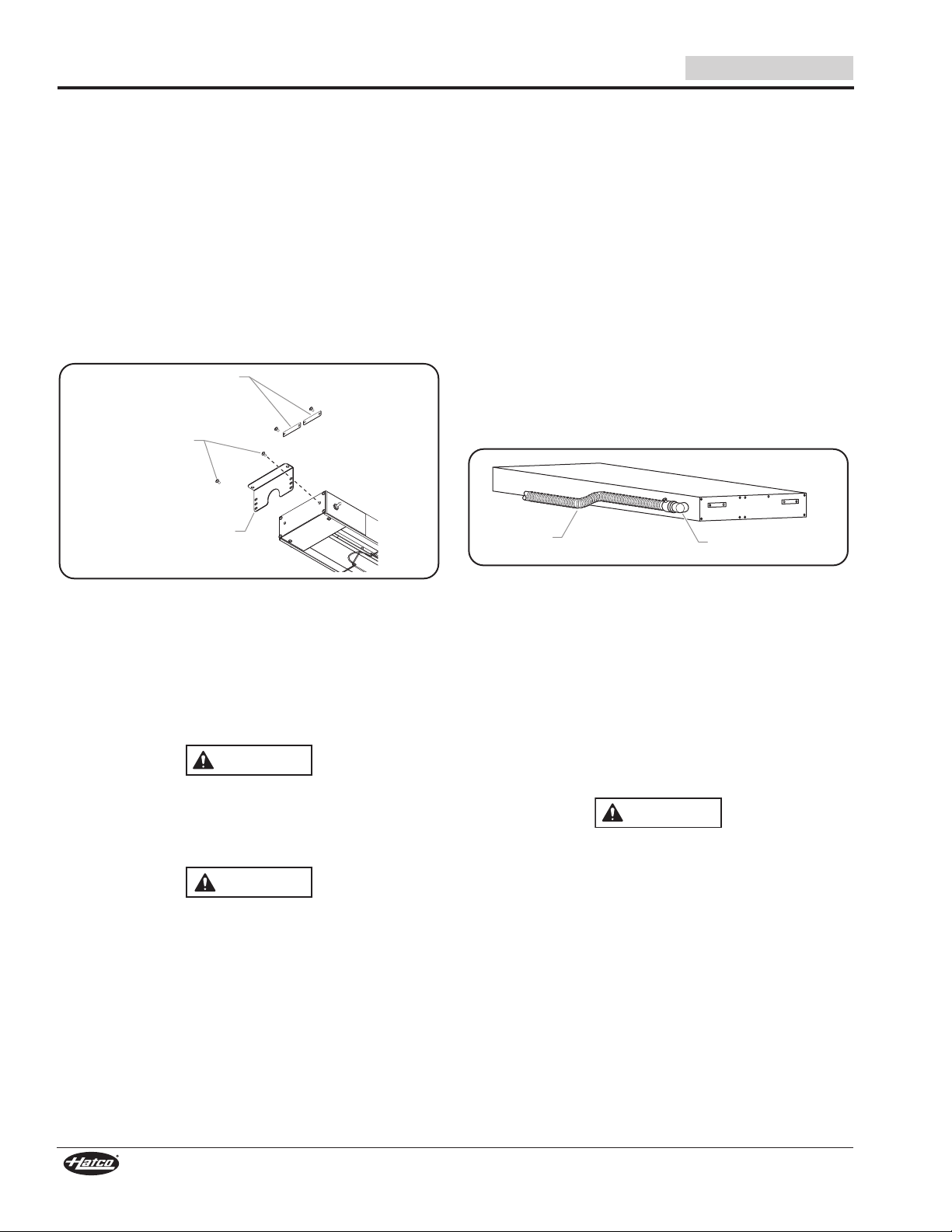
Adjustable Angle Bracket Mounting on
Stainless Steel Models
Use the following procedure to install adjustable angle brackets
on each end of stainless steel housing models (GR and
GRH models).
1. Position the unit on a flat surface with the heating element
facing down.
2. Remove the two hanger tab screws and hanger tabs.
3. Align the adjustable angle bracket with the hanger tab
mounting holes on the unit.
4. Secure the angle bracket with the previously removed
hanger tab screws.
5. Fasten the angle brackets to the underside of the shelf
using appropriate fasteners (not supplied by Hatco).
Power Supply
Install supply wire and connectors suitable for at least 194°F
(90°C).
• Use a minimum of No. 14 AWG copper wire for individual
circuits up to 15 amps.
• Use a minimum of No. 12 AWG copper wire for individual
circuits 15 to 20 amps.
• Use a minimum of No. 10 AWG copper wire for individual
circuits 20 to 25 amps.
• Use a minimum of No. 8 AWG copper wire for individual
circuits 25 to 30 amps.
NOTE: Refer to the wiring diagram supplied with the unit and
specifications label attached to the unit for specific
electrical information.
Conduit Connection
Units supplied with a right angle fitting and flexible conduit
attached have had all internal connections completed at the
factory. Attach the proper power supply leads to the high
temperature lead wires in the conduit.
Stainless Steel Model Adjustable Angle Bracket Installation
Electrical Information
Refer to the wiring diagram supplied with the unit and
specification label attached to the unit for specific electrical
information. Also, refer to the “Electrical Rating Charts”
document on the Infrared Strip Heaters page of the Hatco
website (www.hatcocorp.com).
ELECTRIC SHOCK HAZARD: For hardwired units, all
electrical connections must be in accordance with local
electrical codes and any other applicable codes.
Connections should be made by a qualified, licensed
electrician.
Strip heaters equipped with incandescent lights that
require a circuit breaker larger than 20 amps for the heat
element must have a separate circuit breaker for the
incandescent lights that is 20 amps or less.
NOTE: If the unit being installed is not shown or listed in this
manual, refer to the wiring diagram supplied with the
unit and the installation information on the unit for
further instructions.
Conduit Connections
Power Cord and Plug Models
Units can be supplied with a 6′ (1829 mm) power cord and plug
attached at the factory if the unit meets the following guidelines:
• 120 volt unit
• Single heating element
• 72″ (1829 mm) or less in length
• Built-in switch
• Portable mounting using C-Legs or T-Legs supplied by
Hatco or stationary mounting using “S” hooks and mounting
chain supplied by Hatco.
ELECTRIC SHOCK HAZARD: Plug unit into a properly
grounded electrical receptacle of the correct voltage, size,
and plug configuration. If plug and receptacle do not
match, contact a qualified electrician to determine and
install proper voltage and size electrical receptacle.
NOTE: Units intended for fixed or permanent mounting cannot
have a power cord attached and must be hardwired
according to local and national electrical codes.
12
Form No. GRM-0115
Page 13

English
NOTICE
D
O
N
O
T
I
N
S
T
A
L
L
E
N
C
L
O
S
U
R
E
I
N
T
H
I
S
A
R
E
A
D
O
N
O
T
I
N
S
T
A
L
L
E
N
C
L
O
S
U
R
E
I
N
T
H
I
S
A
R
E
A
Mounting
Screw
Mounting
Flange
Mounting
Flange
Heat
INSTALLATION
Remote Control Enclosures
Hatco remote control enclosures include switches, wire leads,
and/or indicator lights and are shipped ready for installation.
The RMB Series require one remote control enclosure per strip
heater. The RMB2 Series allows multiple strip heaters to be
connected to one remote control enclosure.
NOTE: Remote control enclosures are available in several
configurations depending on the model. All enclosures
are built in accordance with UL standards to
accommodate switches, indicator lights, and wiring. See
the OPTIONS AND ACCESSORIES section for more
information.
IMPORTANT NOTE:
Remote mounted enclosures and control switches must be
installed in a cool, dry location as far away from any heat zone
as possible. Do not mount enclosures or switches directly on,
under, or above unit. Do not mount enclosures or switches in
direct contact with any heated surface or near any steam
generating equipment.
Remote Mounted Control Switches
Optional remote mounted control switches include ON/OFF
toggle switches and infinite control switches. These switches
need to be installed into an approved electrical box/enclosure
(not supplied) by a qualified electrician. See the OPTIONS AND
ACCESSORIES section for more information.
NOTE: When two or more units are mounted where the heat
from one housing tends to raise the temperature of
another, the control switches should be installed in a
remote control enclosure. Units in a multiple installation
should use remote mounted control switches.
To prevent premature failure of components due to
excessive heat, remote mounted control switches must be
installed outside the strip heater heat zone.
Form No. GRM-0115
Remote Mounted Enclosure Installation Locations
13
Page 14

OPERATION
CAUTION
WARNING
ON/OFF (I/O)
Toggle Switch
Infinite
Control
Indicator Light
Infinite
Control
ON/OFF (I/O)
Toggle Switch
Indicator
Light
RMB Series
RMB2 Series
General
Glo-Ray®Infrared Strip Heaters are designed for ease of
operation. Use the following information and procedures to
operate the unit.
Read all safety messages in the IMPORTANT SAFETY
INFORMATION section before operating this equipment.
BURN HAZARD: Some exterior surfaces on unit will get
hot. Use caution when touching these areas.
Standard and approved manufacturing oils may smoke up
to 30 minutes during initial startup. This is a temporary
condition. Operate unit without food product until smoke
dissipates.
Controls
Strip heaters come standard with controls mounted to the unit
or with optional remote mounted controls. The following is a list
of the available controls for the strip heaters.
ON/OFF (I/O) Toggle Switch—Turns power on and off to the
heating elements and/or the lights (depending on control
configuration).
Infinite Control—Turns on the power and controls the
temperature of the heating elements. The infinite control is
available either built-in or on a remote control enclosure.
NOTE: Dual units cannot be equipped with built-in infinite
Lights ON/OFF Toggle Switch—Turns power on and off to the
lights.
Indicator Light—Illuminates when power is on, shuts off when
power is off.
NOTE: Toggle switches cannot be used on circuits that exceed
Startup
NOTE: Allow 15–20 minutes to reach operating temperature.
controls.
15 amps. Infinite controls cannot be used on circuits that
exceed 12.2 amps.
1. Turn on the heating element(s). The indicator light (if
equipped) will illuminate and the heating elements will
energize.
• If unit is equipped with a ON/OFF (I/O) toggle switch,
move the toggle switch to the ON (I) position.
• If unit is equipped with an optional infinite control(s), turn
the control to the desired setting.
2. On models equipped with display lights, move the light
ON/OFF (I/O) toggle switch to the ON (I) position.
English
Control Panel with ON/OFF (I/O) Toggle Switch
Remote Control Enclosures
NOTE: Refer to the OPTIONS AND ACCESSORIES section
for remote control enclosure information.
Shutdown
1. Move the ON/OFF (I/O) toggle switch to the OFF (O)
position or turn the optional infinite control(s) to the
OFF (O) position.
• The indicator light (if equipped) will shut off and the
heating elements will shut down.
2. On models equipped with display lights, move the light
ON/OFF (I/O) toggle switch to the OFF (O) position.
14
Form No. GRM-0115
Page 15

English
WARNING
NOTICE
WARNING
MAINTENANCE
General
Glo-Ray Infrared Strip Heaters are designed for maximum
durability and performance with minimum maintenance.
ELECTRIC SHOCK HAZARD:
• Turn OFF power switch, unplug power cord/turn off
power at circuit breaker, and allow unit to cool before
performing any cleaning, adjustments, or maintenance.
• DO NOT submerge or saturate with water. Unit is not
waterproof. Do not operate if unit has been submerged
or saturated with water.
• Do not steam clean or use excessive water on unit.
• This unit is not “jet-proof” construction. Do not use jetclean spray to clean this unit.
This unit has no “user-serviceable” parts. If service is
required on this unit, contact an Authorized Hatco Service
Agent or contact the Hatco Service Department at
800-558-0607 or 414-671-6350; fax 800-690-2966; or
International fax 414-671-3976.
Use only Genuine Hatco Replacement Parts when service
is required. Failure to use Genuine Hatco Replacement
Parts will void all warranties and may subject operators of
the equipment to hazardous electrical voltage, resulting in
electrical shock or burn. Genuine Hatco Replacement Parts
are specified to operate safely in the environments in which
they are used. Some aftermarket or generic replacement
parts do not have the characteristics that will allow them to
operate safely in Hatco equipment.
Replacing Display Light Bulbs
Use only light bulbs that meet or exceed National
Sanitation Foundation (NSF) standards and are specifically
designed for food holding areas. Breakage of light bulbs
not specially coated could result in personal injury and/or
food contamination.
The display light is an incandescent or optional halogen bulb
that illuminates the warming area. These bulbs have a special
coating to guard against injury and food contamination in the
event of breakage.
To replace a display light bulb:
1. Disconnect the power supply and wait until the unit has
cooled.
2. Unscrew the light bulb from the unit and replace it with a
new, specially-coated incandescent or optional halogen
bulb.
NOTE: Hatco shatter-resistant light bulbs meet NSF standards
for food holding and display areas. For 100, 120,
120/208, and 120/240 volt applications, use Hatco
P/N 02.30.043.00. For 200, 220/240, and 230 volt
applications, use Hatco P/N 02.30.058.00.
NOTE: Halogen bulbs are available as an option for aluminum
housing models only. For 120, 120/208, and 120/240
volt applications, use Hatco P/N 02.30.081.00.
Use non-abrasive cleaners and cloths only. Abrasive
cleaners and cloths could scratch the finish of the unit,
marring its appearance and making it susceptible to soil
accumulation.
IMPORTANT—DO NOT use paper towel or glass cleaner to
clean plastic surfaces. Paper towel and glass cleaner may
scratch the material. Wipe off plastic surfaces using a soft,
clean, water-dampened cloth.
Cleaning
To preserve the finish of the strip heater, it is recommended that
all surfaces be cleaned daily.
1. Turn off the unit and allow the unit to cool.
2. Wipe down all metal surfaces with a water-dampened, nonabrasive cloth. Stubborn stains may be removed with a
good stainless steel or non-abrasive cleaner. Clean hard
to reach areas using a small brush and mild soap.
3. Wipe dry the entire unit using a non-abrasive, dry cloth.
4. If equipped, clean the plastic sneeze guards using soft
cleaning cloths, mild soap, and water. NOTICE: Do not
use paper towel or glass cleaner on plastic surfaces—
scratching may occur.
Form No. GRM-0115
15
Page 16

TROUBLESHOOTING GUIDE
WARNING
WARNING
CAUTI
O
N
-
HO
T
G
L
O
-
RA
Y
F
o
o
d
w
a
r
m
e
r
H
A
T
C
O
C
O
R
P
.
M
I
L
W
A
U
K
E
E
,
W
I
U
.S
.
A
.
O
N
O
F
F
O
P
A
R
T
S
&
S
E
R
V
I
C
E
A
S
S
I
S
T
A
N
C
E
WWW
.
H
A
T
C
O
C
O
R
P
.
C
O
M
8
0
0
-5
5
8
-
0
6
0
7
H
AT
C
O
C
O
R
P
.
M
I
L
WA
U
K
E
E
,
W
I
U
.
S
.
A
.
O
N
O
F
F
O
Tab Screw
Acorn Nut
Support Bar
Sneeze Guard
Channel
English
This unit must be serviced by qualified personnel only.
Service by unqualified personnel may lead to electric
shock or burn.
ELECTRIC SHOCK HAZARD: Turn OFF power switch,
unplug power cord/turn off power at circuit breaker, and
allow unit to cool before performing any cleaning,
adjustments, or maintenance.
Symptom Probable Cause Corrective Action
Unit is turned “On” but there
is no heat.
Heat is inadequate. Unit mounted too high above target area. Lower unit, putting effective heat closer to target.
Heat is excessive. Unit mounted too close to target area. Check to see that installation is within specifications for
Control switches burn out. Unit mounted improperly. Move the unit the proper distance away from walls,
No power to unit. Check circuit breaker and reset as necessary.
Switch is defective. Contact Authorized Service Agent or Hatco for assistance.
Wiring is open. Contact Authorized Service Agent or Hatco for assistance.
Heating element defective. Contact Authorized Service Agent or Hatco for assistance.
Excessive air movement around strip
heater target area.
Restrict or redirect air movement (air conditioning duct
or exhaust fan) away from unit.
Incorrect power supply (low). Check power supply to unit, making sure it matches
rating on the unit. If power supply is incorrect, change to
match rating on unit.
type/model. Increase mounting height if too close.
Voltage supply too high. Check power supply to unit, making sure it matches
rating on unit. If power supply is incorrect, change to
match rating.
counters, and/or pass-through shelves. Refer to the
INSTALLATIONsection for guidelines.
Remote control enclosure is mounted
Move remote control enclosure away from the heat zone.
too close to the heat zone.
Switches used are not Hatco supplied. Genuine Hatco Parts are specified to operate safely and
properly in the environment in which they are used.
Contact Authorized Service Agent or Hatco to replace
switches with Genuine Hatco Replacement Parts.
OPTIONS AND ACCESSORIES
Sneeze Guards
Optional sneeze guards are available for aluminum models
only. They are available in sizes of 9-3/8″ (238 mm) and 14″
(356 mm). Sneeze guards can be installed on either one side or
both sides of the unit.
To install a sneeze guard:
1. Remove the protective paper from the sneeze guard.
2. Assemble each tab screw through the top of the sneeze
guard and through the support bar. Loosely thread an
acorn nut onto each of the tab screws below the support
bar.
3. Lift the sneeze guard assembly and carefully slide each of
the tab screws that are loosely attached to the sneeze
guard into the channel on the unit.
4. Align each end of the sneeze guard with the ends of the
unit and then tighten the acorn nuts to secure the sneeze
guard in position. Do not over-tighten the acorn nuts.
16
Installing Sneeze Guards
Form No. GRM-0115
Page 17

English
D
E
C
B
A
Side View
Top View
Front View
Toggle Switch
Infinite Control
Wiring
Access
Cover
Knockout
Terminal Block
Cover
Screw
Relay
Indicator
Light
OPTIONS AND ACCESSORIES
Remote Control Enclosures — RMB Series
RMB Series remote control enclosures are available in various
configurations for use with strip heaters. Remote control
enclosures locate controls away from the heat of the unit,
increasing the life span of the controls. All models are built in
accordance with UL standards with switches, indicator lights,
and wiring. Consult the factory for type and location of RMB
Series controls for enclosure.
NOTE: RMB Series remote control enclosures require one
Dimensions
remote control enclosure per strip heater.
1. Determine the area to mount the RMB box.
IMPORTANT NOTE:
Remote mounted enclosures and control switches must be
installed in a cool, dry location as far away from any heat zone
as possible. Do not mount enclosures or switches directly on,
under, or above unit. Do not mount enclosures or switches in
direct contact with any heated surface or near any steam
generating equipment.
Models
RMB-3
Series
RMB-7
Series
RMB-14
Series
RMB-16
Series
RMB-20
Series
Width
(A)
5-15/16″
(150 mm)3″(76 mm)
9-3/8″
(239 mm)3″(76 mm)
14-3/8″
(366 mm)3″(76 mm)
16-3/8″
(417 mm)3″(76 mm)
20-3/8″
(518 mm)3″(76 mm)
Depth
(B)
Height
(C)
2-5/8″
(67 mm)
2-5/8″
(67 mm)
2-5/8″
(67 mm)
2-5/8″
(67 mm)
2-5/8″
(67 mm)
Screw
Width
(D)
6-5/16″
(161 mm)
9-13/16″
(249 mm)
14-13/16″
(376 mm)
16-13/16″
(427 mm)
20-13/16″
(529 mm)
Screw
Height
(E)
1-5/8″
(41 mm)
1-5/8″
(41 mm)
1-5/8″
(41 mm)
1-5/8″
(41 mm)
1-5/8″
(41 mm)
3. Remove the wiring access cover on bottom of the control
enclosure by removing screws and sliding cover off.
4. Identify and remove the appropriate knockouts from the
control enclosure for the electrical connections.
5. Attach conduit connectors to the knockouts in the control
enclosure.
Removing Wiring Access Cover
6. Make the electrical connections between the unit and the
output terminals on the terminal block or wire leads inside
the control enclosure. Refer to the wiring diagrams included
with the unit and the RMB control enclosure.
NOTE: To ground the RMB, use either a separate ground wire,
metallic conduit, or other locally accepted method in
accordance with the National Electric Code (NEC) or
Canadian Electric Code (CEC).
7. Tie all ground leads (green and/or green/yellow leads)
together and terminate with a UL Listed wire nut.
8. Make the electrical connections between the power supply
and the input terminals on the terminal block or wire leads
inside the control enclosure. Refer to the wiring diagram
included with the RMB control enclosure.
NOTE: Verify which wire leads from the foodwarmer are for
phase, neutral, and/or lighting connections, as
applicable.
9. Make sure all wire connections are tight, and secure both
conduit runs to the conduit connectors.
10. Reinstall the wiring access cover on bottom of the control
enclosure.
11. Turn on power at the fused disconnect switch/circuit
breaker, turn on the unit, and test operation.
2. Secure the RMB to the mounting surface using appropriate
screws or fasteners.
• Use the mounting flange on each end of the RMB.
Control Enclosure Dimensions
NOTE: Sizing of the power supply wire leads and upstream
overcurrent protection must conform with National
Electric Code (NEC) requirements as well as all local
codes.
Form No. GRM-0115
17
Page 18

OPTIONS AND ACCESSORIES
Top View
A
B
C
E
Front View
Side View
D
B
A
E
D
C
WARNING
NOTICE
LINE
100V
120V
208V
240V
NEUTRAL
NEUTRAL
208V
240V
LOAD
NOTICE
English
Remote Control Enclosure — RMB2 Series
RMB2 Series remote control enclosures allow multiple strip
heaters to be wired to and controlled by a single enclosure. The
total amp draw of all connected strip heaters cannot exceed the
rating of the remote control enclosure. Consult the factory for
information regarding the proper RMB2 Series remote control
enclosure for a specific application. Refer to the Instruction
Sheet included with the enclosure for installation information.
RMB2 Series Dimensions
Models
RMB2-1R
RMB2-2R
Width
(A)
10-1/8″
(257 mm)
13-1/8″
(333 mm)
Width
(B)
11″
(279 mm)
14″
(356 mm)
Height
(C)
5-1/2″
(140 mm)
5-1/2″
(140 mm)
Depth
(D)
4-1/4″
(109 mm)
4-1/4″
(109 mm)
Height
(E)
4-5/8″
(116 mm)
4-5/8″
(116 mm)
Infinite Switch
Use the following procedure to install an infinite switch. An
infinite switch needs to be installed into an approved electrical
box/enclosure (not supplied) by a qualified electrician.
ELECTRIC SHOCK HAZARD: Turn OFF power switch,
disconnect unit from power source, and allow unit to cool
before performing any cleaning, adjustments, or maintenance.
To prevent premature failure of components due to
excessive heat, remote mounted control switches must be
installed outside the strip heater heat zone.
1. Verify unit is off and disconnected from the power source.
2. Install the infinite switch. Refer to the wiring diagram for
proper electrical connections. Make sure the switch is
installed with the “H1” terminal oriented on top. This will
ensure that the switch functions match the markings on
the switch label.
• Power In: L1 and L2 (for 100V and 120V units, L2 is
neutral)
• To Heating Element: H1 and H2
NOTE: The terminals on the infinite switch are specially
designed, high-temperature rated terminals that do not
require solder connections.
Dimensions — RMB2s
RMB2 Series Cutout Dimensions
Opening Cutout
Dimensions
Models
RMB2-1R
RMB2-2R
(A) (B) (C) (D) (E)
4-3/4″
(121 mm)
4-3/4″
(121 mm)
10-1/8″
(257 mm)
13-1/8″
(333 mm)
(29 mm)
(29 mm)
Cutout Dimensions — RMB2s
NOTE: Make sure the width of the cutout does not exceed the
dimension given for each size enclosure.
1-1/8″
1-1/8″
Screw Hole
Dimensions
2-1/2″
(64 mm)
2-1/2″
(64 mm)
10-7/16″
(265 mm)
13-7/16″
(341 mm)
The infinite switch must be installed using the terminals
and wires supplied with the switch. Failure to use the
supplied Genuine Hatco Replacement Parts will void all
warranties and may damage the equipment.
Infinite Switch Wiring Diagram (rear view)
NOTE: Make sure the switch is installed with the “H1” terminal
oriented on top (“12 o’clock” position), as shown above.
This will ensure that the switch functions match the
markings on the switch label.
Infinite Switch Kit Part Numbers
Part Number
Voltage
R02.19.160.00 100 volt
R02.19.018.00 120 volt
R02.19.017.00 208 volt
R02.19.019.00 240 volt
18
Form No. GRM-0115
Page 19

English
LIMITED WARRANTY
1. PRODUCT WARRANTY
Hatco warrants the products that it manufactures (the
“Products”) to be free from defects in materials and
workmanship, under normal use and service, for a period of one
(1) year from the date of purchase when installed and
maintained in accordance with Hatco’s written instructions or
18 months from the date of shipment from Hatco. Buyer must
establish the Product’s purchase date by registering the Product
with Hatco or by other means satisfactory to Hatco in its sole
discretion.
Hatco warrants the following Product components to be free
from defects in materials and workmanship from the date of
purchase (subject to the foregoing conditions) for the period(s)
of time and on the conditions listed below:
a) One (1) Year Parts and Labor PLUS One (1) Additional
Year Parts-Only Warranty:
Conveyor Toaster Elements (metal sheathed)
Drawer Warmer Elements (metal sheathed)
Drawer Warmer Drawer Rollers and Slides
Strip Heater Elements (metal sheathed)
Display Warmer Elements (metal sheathed air heating)
Holding Cabinet Elements (metal sheathed air heating)
Heated Well Elements — HW and HWB Series
(metal sheathed)
b) One (1) Year Parts and Labor PLUS Four (4) Years
Parts-Only Warranty:
3CS and FR Tanks
c) One (1) Year Parts and Labor PLUS Nine (9) Years
Parts-Only Warranty on:
Electric Booster Heater Tanks
Gas Booster Heater Tanks
d) Ninety (90) Day Parts-Only Warranty:
Replacement Parts
THE FOREGOING WARRANTIES ARE EXCLUSIVE AND IN
LIEU OF ANY OTHER WARRANTY, EXPRESSED OR
IMPLIED, INCLUDING BUT NOT LIMITED TO ANY IMPLIED
WARRANTY OF MERCHANTABILITY OR FITNESS FOR A
PARTICULAR PURPOSE OR PATENT OR OTHER
INTELLECTUAL PROPERTY RIGHT INFRINGEMENT.
Without limiting the generality of the foregoing, SUCH
WARRANTIES DO NOT COVER: Coated incandescent light
bulbs, fluorescent lights, heat lamp bulbs, coated halogen light
bulbs, halogen heat lamp bulbs, xenon light bulbs, LED light
tubes, glass components, and fuses; Product failure in booster
tank, fin tube heat exchanger, or other water heating equipment
caused by liming, sediment buildup, chemical attack, or
freezing; or Product misuse, tampering or misapplication,
improper installation, or application of improper voltage.
2. LIMITATION OF REMEDIES AND DAMAGES
Hatco’s liability and Buyer’s exclusive remedy hereunder will
be limited solely, at Hatco’s option, to repair or replacement
using new or refurbished parts or Product by Hatco or a Hatcoauthorized service agency (other than where Buyer is located
outside of the United States, Canada, United Kingdom, or
Australia, in which case Hatco’s liability and Buyer’s exclusive
remedy hereunder will be limited solely to replacement of part
under warranty) with respect to any claim made within the
applicable warranty period referred to above. Hatco reserves
the right to accept or reject any such claim in whole or in part.
In the context of this Limited Warranty, “refurbished” means a
part or Product that has been returned to its original
specifications by Hatco or a Hatco-authorized service agency.
Hatco will not accept the return of any Product without prior
written approval from Hatco, and all such approved returns shall
be made at Buyer’s sole expense. HATCO WILL NOT BE
LIABLE, UNDER ANY CIRCUMSTANCES, FOR
CONSEQUENTIAL OR INCIDENTAL DAMAGES, INCLUDING
BUT NOT LIMITED TO LABOR COSTS OR LOST PROFITS
RESULTING FROM THE USE OF OR INABILITY TO USE THE
PRODUCTS OR FROM THE PRODUCTS BEING
INCORPORATED IN OR BECOMING A COMPONENT OF
ANY OTHER PRODUCT OR GOODS.
Form No. GRM-0115
19
Page 20

AVIS
ATTENTION
AVERTISSEMENT
Service d'assistance et de pièces de
rechange disponible 7j/7, 24h/24 aux
États-Unis et au Canada en composant
le 800-558-0607.
SOMMAIRE
Français
Informations Importantes pour le Propriétaire .....................20
Introduction.........................................................................20
Consignes de Sécurité Importantes .................................21
Description du Modèle .......................................................22
Désignation du Modèle ......................................................23
Caractéristiques Techniques.............................................23
Configuration des Fiches..................................................23
Dimensions.......................................................................24
Installation...........................................................................25
Généralités .......................................................................25
Hauteurs Recommandées pour le Montage ....................26
Dégagement Minimum exigé en cas d'environnement
Combustible ....................................................................26
Dégagement Minimum Exigé en cas d'environnement
Non Combustible ............................................................27
Installation d'unités Mobiles..............................................28
Installation d'unités Suspendues à des Chaînes .............29
Installation d'unités Permanentes.....................................29
Informations sur le câblage électrique .............................31
Mode d'emploi.....................................................................33
Généralités .......................................................................33
Maintenance ........................................................................34
Nettoyage .........................................................................34
Remplacement du tube d'éclairage..................................34
Guide de Dépannage ..........................................................35
Options et Accessoires......................................................35
Garantie Limitée..................................................................38
Autorisés Distributeurs de Pièces........Couverture Arrière
INFORMATIONS IMPORTANTES POUR LE PROPRIÉTAIRE
Notez le numéro de modèle, le numéro de série, la tension et la
date d'achat de l'appareil dans les espaces ci-dessous (étiquette
de spécification située sur le côté de l'appareil). Veuillez avoir
cette information à portée de la main si vous appelez Hatco pour
assistance.
Modèle No. ______________________________________
Numéro de série __________________________________
Voltage __________________________________________
Date d’achat ______________________________________
Horaires
ouvrables: 8h00 à 17h00
Heure du Centre des États-Unis (CST)
(Horaires d’été : juin à septembre—
8h00 à 17h00 CST du lundi au jeudi
8h00 à 14h30 CST le vendredi)
Téléphone: 800-558-0607; 414-671-6350
Courriel: partsandservice@hatcocorp.com
Télécopieur: 800-690-2966 (Pièces et Service après-vente)
414-671-3976 (Internationale)
Enregistrez votre appareil!
Remplissez la garantie en ligne pour éviter les retards pour
faire jouer la garantie. Accédez au site Web Hatco
www.hatcocorp.com, sélectionnez le menu déroulant Parts
& Service, puis cliquez sur Warranty Registration.
INTRODUCTION
Les rampes chauffantes à infrarouge Glo-Ray®garantissent une
durée de conservation des aliments maximale et minimisent le
risque de maladie d'origine alimentaire. Une sécurité et une qualité
optimum sont le résultat de la conservation des aliments aux
bonnes températures de service en utilisant les schémas de
chaleur préétablis par Glo-Ray's. Le profil de chaleur pré-focalisé
empêche les aliments d'être trop cuits au milieu et tièdes sur les
bords, en concentrant des températures plus élevées vers les
bords extérieurs des surfaces de service, où la perte de chaleur
est la plus importante. Grâce à des réflecteurs spécialement
conçus pour diriger la chaleur à partir de l'élément, les rampes
chauffantes Glo-Ray permettent aux aliments de conserver des
températures de service bien réparties en toute sécurité, et ce
sans les cuire au-delà de leur point de cuisson optimale.
Les rampes chauffantes à infrarouge Glo-Ray sont disponibles
en sortie d'usine avec ou sans lampes à incandescence
résistantes à l'éclatement destinées à éclairer la zone de
maintien au chaud. Ces ampoules possèdent un enduit spécial
destiné à éviter toute blessure et toute contamination des
éléments en cas de casse.
Les rampes chauffantes à infrarouge Glo-Ray sont des produits
issus d'une recherche approfondie ; elles ont subi des essais
sur le terrain. Les matériaux utilisés ont été sélectionnés pour
un maximum de durabilité, d'aspect esthétique et de
performance optimum. Chaque appareil est minutieusement
inspecté et testé avant expédition.
Des renseignements supplémentaires sont disponibles sur
notre site Web à www.hatcocorp.com.
on
i
sat
i
l
i
'ut
l
en,
i
ret
u
n
l’e
onnem
ti
er
s
i
l
isse
a
r
d
rs
mb
se
'apparei
l
n
'ent
e
t
b
ent
d
a
in
s
e
d
le
enues
ont
c
.
l
ma
ce
s
n
a
str
n
ctio
u
dans
so
l
e
u
n
-Ra
Glo
e
d
e
d
n
Ce m
t le
e
a
H
i
d’
e m
c
e
L
identifiées par les mots indicateurs suivants :
AVERTISSEMENT indique une situation dangereuse qui, si
elle n’est pas évitée, peut provoquer la mort ou des
blessures graves.
ATTENTION indique une situation dangereuse qui, si elle
n’est pas évitée, peut provoquer des blessures légères ou
moyennes.
AVIS est utilisé pour des questions sans rapport avec des
blessures corporelles.
tco
ns
s
fo
tal
anuel
n
co
n
vo
l
at
sig
tio
c
u
on,
i
s
av
n
e
m
e
n
n
mma
co
e
r
éc
s
de
d’
ant
sé
e
d
s
e
ré
s
e
t d
n
e
d
n
et
é
t
uri
er
l
tal
ns
i
ité
r
cu
q
c
e
d
de
et d’
i
u
h
a
u
a
e
lir
fonc
ut
pa
p
ffe
i
ons pour l
i
ruct
nst
des i
t
ourni
f
anuel
.
y
s
t
n
20
Formulaire n° GRM-0115
Page 21

Français
AVIS
ATTENTION
AVERTISSEMENT
AVERTISSEMENT
CONSIGNES DE SÉCURITÉ IMPORTANTES
Lisez l'information de securite importante suivante avant d'utiliser cet équipement pour éviter
des dommages ou la mort sérieux et pour éviter d'endommager l'équipement ou la propriété.
DANGER DE DÉCHARGE ÉLECTRIQUE :
• Les appareils fournis sans câble et prise électrique nécessitent
une connexion câblée au système électrique sur place. La
connexion doit être correctement mise à la terre et doit
correspondre au voltage, à la taille et à la configuration
correspondant aux spécifications de l'appareil. Contactez un
électricien qualifié pour déterminer et installer la connexion
électrique adaptée.
• Branchez l'unité à une prise correctement reliée à la terre et
possédant le voltage, la dimension et la configuration
adéquats. Si la fiche et la prise ne correspondent pas,
contactez un électricien qualifié afin de déterminer et
d'installer une prise électrique possédant la taille et la tension
adéquate.
• Tournez le interrupteur sur « ARRÊT » pour éteindre la rampe,
débranchez le cordon d'alimentation/coupez le courant au
disjoncteur et laissez refroidir l'unité avant d'effectuer toute
opération de nettoyage, de réglage ou d'entretien.
• NE PAS immerger l’appareil ni le saturer d’eau. L’appareil n’est
pas étanche à l’eau. Ne pas le faire fonctionner s’il a été
immergé ou saturé d’eau.
• Ne pas nettoyer à la vapeur ni utiliser trop d’eau sur l’appareil.
• Cet appareil n’est pas étanche aux jets. Ne pas utiliser de jet
sous pression pour nettoyer l’appareil.
• Interrompez l'utilisation de l'unité si le cordon d'alimentation
est effiloché ou usé.
• N'essayez jamais de réparer ou de remplacer un cordon
d'alimentation endommagé. Celui-ci devra être remplacé par
Hatco, un agent de service agréé par Hatco ou une personne
possédant des qualifications similaires.
• Utilisez uniquement des pièces de rechange d'origine Hatco
lorsque l'entretien est nécessaire. Utilisez des pièces
détachées Hatco authentiques sous peine d'annuler toutes les
garanties et d'exposer l’utilisateur à des tensions électriques
dangereuses pouvant entraîner une électrocution ou des
brûlures. Les pièces de rechange authentiques Hatco sont
spécifiées pour fonctionner en toute sécurité dans les
environnements dans lesquels elles sont utilisées. Certaines
pièces de rechange génériques ou d'après-vente n'ont pas les
caractéristiques qui leur permettent d'opérer en toute sécurité
dans les équipements Hatco.
DANGER D’INCENDIE :
• Positionnez l'unité à bonne distance des murs et matériaux
combustibles. Si les distances de sécurité ne sont pas
respectées, une décoloration ou combustion peut avoir lieu.
Reportez-vous aux informations spécifiques d'installation et
de montage de ce manuel pour connaître les dégagements
adéquats.
• Assurez-vous de suivre les informations d'installation cidessous pour des rampes chauffantes spécifiques. Si les
distances de sécurité ne sont pas respectées, une
décoloration ou combustion peut avoir lieu.
a. N'installez pas de rampes chauffantes de puissance
standard (séries GR, GRA, GRN, GRL et GRAL) à moins de
254 mm (10″) au-dessus d'une surface combustible.
b. N'installez pas de rampes chauffantes à haute puissance
(séries GRH, GRHL, GRAH, GRNH, GRAHL) à moins de
343 mm (13 1/2″) au-dessus d'une surface combustible.
c. N'installez pas de rampes chauffantes doubles au-dessus
d'une surface combustible.
Cet appareil ne contient aucune pièce réparable par l’utilisateur.
Si cet appareil doit être réparé, contacter un réparateur Hatco
agréé ou le Service après-vente Hatco au 800-558-0607 ou
414-671-6350 ; télécopieur 800-690-2966; télécopieur internationale
414-671-3976.
N'utiliser que des ampoules électriques qui correspondent ou qui
surpassent les standards de la Fondation Nationale des Affaires
Sanitaires (NSF) et qui sont spécifiquement conçus pour les
espaces de conservation des aliments. La casse d'ampoules
électriques non enduites de manière spécifique pourrait entraîner
des lésions corporelles et/ou une contamination des aliments.
RISQUE D'EXPLOSION: Ne conservez pas ou n'utilisez pas
d'essence ou d'autres vapeurs ou liquides inflammables à
proximité de cet appareil ou de tout autre appareil.
Cet appareil ne doit pas être utilisé par des enfants ou des
personnes avec des capacités physiques, sensorielles ou
mentales diminuées. Assurez-vous que les enfants sont bien
surveillés et tenez-les à l'écart de l'appareil.
Assurez-vous que tous les opérateurs ont été formés à l'utilisation
sûre et correcte de l'appareil.
S'assurer que le produit alimentaire a été chauffé à une
température adaptée au maintien de sa salubrité avant de le mettre
dans l'appareil sous peine de risques graves pour la santé. Cet
appareil est destiné au maintien au chaud de produits alimentaires
préchauffés uniquement.
Pour l'installation avec des chaînes, assurez-vous que les chaînes
sont suffisamment résistantes et qu'elles sont solidement fixées à
la fois sur le réchauffeur de bande et sur l'espace de montage. Des
chaînes mal installées peuvent entraîner le relâchement et la chute
du réchauffeur. Ne rien placer sur des réchauffeurs installés avec
des chaînes.
DANGER DE BRÛLURE : Certaines surfaces extérieures de
l’appareil deviennent chaudes. Toucher ces zones de l’appareil
avec précaution.
Les graisses standards et approuvées utilisées lors de la
fabrication peuvent provoquer des fumées au cours du démarrage
initial pendant 30 minutes. Il s'agit d'un état temporaire. Utilisez
l'appareil sans produit alimentaire jusqu'à ce que la fumée
disparaisse.
Les rampes chauffantes équipées de lumières incandescentes qui
nécessitent un disjoncteur de plus de 20 ampères pour l'élément
chauffant doivent avoir un disjoncteur séparé pour les lumières
incandescentes de 20 ampères ou moins.
Assurez-vous que le fonctionnement est sûr et adapté. Référezvous aux « Exigences d'espace minimum » indiquées dans la
section Installation de ce manuel.
"L'installation de deux appareils ou plus avec moins de 3 po
(76 mm) entre les boîtiers peut entraîner le défaillance prématurée
des composants. L'incapacité à fournir un espacement adapté
peut entraînerdes dommages causés par la chaleur aux
composants électriques qui ne sont pas couverts par la garantie."
Les unités ne fonctionnent qu'à la tension spécifiée. Reportezvous à l'étiquette des caractéristiques des exigences électriques
avant de commencer l'installation.
Ne masquez pas une rampe chauffante montée sur un passe-plat
avec une sous-face décorative. Une température excessive peut
entraîner une panne de l'unité.
Formulaire n° GRM-0115
21
Page 22

CONSIGNES DE SÉCURITÉ IMPORTANTES
AVIS
AVIS
Français
Pour éviter une défaillance prématurée des composants due à une
chaleur excessive, les interrupteurs de commande à distance
doivent être installés à l'extérieur de la zone de chaleur des
rampes chauffantes.
Les dommages pouvant être causés au dessus de comptoir par
l'équipement de Hatco ne sont pas couverts par la garantie de
Hatco. Contactez le fabricant du comptoir pour les informations
concernant l'application.
DESCRIPTION DU MODÈLE
Tous les Modèles
Les rampes chauffantes à infrarouge Glo-Ray®de Hatco
gardent les aliments chauds à des températures de service
optimales plus longtemps. Les aliments ne se dessèchent et
ne se décolorent pas ; même les plats les plus délicats donnent
l'impression de tout juste sortir du fourneau. Le profil de chaleur
pré-focalisé de Glo-Ray dirige la chaleur émise par un élément
tubulaire afin qu'elle baigne entièrement la surface de service.
Les rampes chauffantes Glo-Ray peuvent être commandées
en configuration « puissance standard » ou « haute puissance
», avec des boîtiers en aluminium de 457 à 3 658 mm
(18″ à 144″) de long, des boîtiers en acier inoxydable de 610 à
2 438 mm (24″ à 996″) de long, ou des boîtiers de style étroit
en acier inoxydable de 457 à 1 829 mm (18″ à 72″) de long.
Toutes les rampes chauffantes bénéficient de plusieurs options
de montage et d'emplacement de l'interrupteur. Des
interrupteurs de commande en continu, des boîtiers de
commande à distance, l'éclairage à incandescence, et des
pare-haleine sont également proposés en option.
Utilisez seulement des nettoyants non abrasifs et des chiffons
doux. Les chiffons et nettoyant abrasifs pourraient érafler la
finition de l'unité, entachant son apparence et la rendant
susceptible à l'accumulation de saleté.
IMPORTANT : n'utilisez PAS de serviettes en papier ou de
nettoyant pour vitres pour nettoyer les surfaces en plastique. Les
serviettes en papier et le nettoyant pour vitres peuvent rayer
l'équipement. Essuyez les surfaces en plastique à l'aide d'un
chiffon doux, propre et humide.
Modèles GRN-XX et GRNH-XX
Les modèles étroits sont disponibles en acier inoxydable, en
acier enduit de poudre, ou en plusieurs couleurs Designer.
NOTA: Les rampes chauffantes de type étroit ne sont pas
disponibles avec des lampes ou des pare-haleine, et ne
sont pas disponibles en unité double.
Modèle GRA-48
Modèles GR-XX, GRL-XX, GRH-XX, et
GRHL-XX
Les modèles en acier inoxydable sont disponibles avec ou sans
les lampes à incandescence.
NOTA: Les rampes chauffantes en acier inoxydable ne
peuvent pas être munies de pare-haleine.
Modèles GRA-XX, GRAH-XX, GRAL-XX, et
GRAHL-XX
Les modèles à élément chauffant unique et à boîtier en
aluminium sont disponibles avec ou sans lampe à
incandescence.
Modèles GR-XXD, GRA-XXD, GRH-XXD,
GRAH-XXD, GRL-XXD, GRAL-XXD,
GRHL-XXD, et GRAHL-XXD
Les modèles doubles permettent d'installer côte à côte deux
rampes ou davantage afin de chauffer une surface de service
plus large (les modèles doubles sont construits avec l'entretoise
obligatoire de 76 mm [3″] ou 152 mm [6″] entre les éléments
de chauffage).
Les modèles doubles sont disponibles avec ou sans lampes à
incandescence ou pare-haleines (les pare-haleines ne sont pas
disponible avec les modèles en acier inoxydable).
NOTA: Ils ne peuvent pas être munis de lampes à
incandescence ni de pare-haleine une fois sortis d'usine.
Modèle GRAHL-48
Modèle GRAL-48D
Modèle GRN-48
22
Formulaire n° GRM-0115
Page 23

Français
AVERTISSEMENT
G R A H L - XX D
Glo-Ray
Type de Boîtier :
A = Aluminum
N = Acier, étroit, enduit de poudre
Pas de Lettre = Acier Inoxydable
Lumière Incandescente
Éléments Doubles
Largeur (en pouces)
H = Haute Puissance
Pas de Lettre = Puissance Standard
NEMA 5-15P
NEMA 5-20P
Configuration des fiches
Un cordon de 1 826 mm (6’) et une fiche d'alimentation peuvent
être installés en usine, en option, pour certaines unités. Ces
unités doivent être des modèles de 120 V avec commande
intégrée de 1 829 mm (72″) ou moins de long et montées avec
un ensemble de chaînes standard, ou montées sur un pied en
C ou en T.
NOTA: Les configurations avec cordons et prises d'alimentation
ne sont pas disponibles avec les appareils avec des
tiges tubulaires réglables ou non-réglables.
DANGER DE DÉCHARGE ÉLECTRIQUE: Brancher
l’appareil sur une prise de courant avec terre de tension, de
format et de configuration des broches corrects. Si la fiche
et la prise ne se correspondent pas, s’adresser à un
électricien qualifié pour déterminer et installer une prise
de courant de format et de tension corrects.
DÉSIGNATION DU MODÈLE
CARACTÉRISTIQUES TECHNIQUES
Configuration des fiches
NOTA: Prise non fournie par Hatco.
NOTA : Référez-vous au diagramme de câblage fourni avec
l'appareil et à l'étiquette de spécification attachée à
l'appareil pour obtenir des informations spécifiques
concernant l'électricité. En outre, se référer à la
"Electrical Rating Charts" document sur la page
Rampes Chauffantes à Infrarouge sur la site Hatco
(www.hatcocorp.com).
Formulaire n° GRM-0115
23
Page 24

CARACTÉRISTIQUES TECHNIQUES
Modèles à élément unique
(présentés avec le pare-haleine facultatif)
A
D
C
B
A
B
C
A
D
C
B
Modèles à double élément
(présentés avec le pare-haleine facultatif)
Modèles étroits
E
E
NOTA: Vous ajouterez 216 mm (8-1/2″) de profondeur
et 44 mm (1-3/4″) de hauteur si l'appareil est
configuré avec un pare-haleine optionnel de
356 mm (14″).
Dimensions
Français
Modéle
GR et GRH
GRA et GRAH
GRAL et GRAHL
GRL et GRHL
GR-, GRA-,
GRH-, GRAH-,
GRL-, GRAL-,
GRHL-, et
GRAHL-XXD
GRN et GRNH
Largeur
(A)
457–2438 mm
(18″–96″)
457–3658 mm
(18″–144″)
457–3658 mm
(18″–144″)
457–1829 mm
(18″–72″)
457–3658 mm
(18″–144″)
457–1829 mm
(18″–72″)
Hauteur
(B)
63 mm
(2-1/2″)
63 mm
(2-1/2″)
63 mm
(2-1/2″)
63 mm
(2-1/2″)
63 mm
(2-1/2″)
51 mm
(2″)
Profonduer
(C)
152 mm
(6″)
152 mm
(6″)
229 mm
(9″)
229 mm
(9″)
Espacement de
76 mm (3″):
381 mm (15″)
Espacement de
152 mm (6″):
457 mm (18″)
102 mm
(4″)
Profonduer
(D)
--- ---
584 mm
(23″)
660 mm
(26″)
660 mm
(26″)
Espacement de
76 mm (3″):
813 mm (32″)
Espacement de
152 mm (6″):
889 mm (35″)
--- ---
Hauteur
(E)
102 mm
(4″)
102 mm
(4″)
102 mm
(4″)
102 mm
(4″)
24
Formulaire n° GRM-0115
Page 25

Français
ATTENTION
AVIS
AVERTISSEMENT
AVIS
INSTALLATION
Généralités
Utilisez les informations contenues dans cette section pour
préparer et installer une rampe chauffante à infrarouge.
Assurez-vous d'appliquer les informations spécifiques au type
d'installation. Lors de l'expédition, la plupart des composants
des rampes chauffantes à infrarouge sont pré-assemblés. Les
unités doubles sont disponibles avec un espaceur nécessaire
de 76 mm (3″) ou 152 mm (6″) pré-assemblé à l'usine.
DANGER D’INCENDIE:
• Positionnez l'unité à bonne distance des murs et
matériaux combustibles. Si les distances de sécurité ne
sont pas respectées, une décoloration ou combustion
peut avoir lieu. Reportez-vous aux informations
spécifiques d'installation et de montage de ce manuel
pour connaître les dégagements adéquats.
• Assurez-vous de suivre les informations d'installation
ci-dessous pour des rampes chauffantes spécifiques.
Si les distances de sécurité ne sont pas respectées, une
décoloration ou combustion peut avoir lieu.
a. N'installez pas de rampes chauffantes de
puissance standard (séries GR, GRA, GRN, GRL et
GRAL) à moins de 254 mm (10″) au-dessus d'une
surface combustible.
b. N'installez pas de rampes chauffantes à haute
puissance (séries GRH, GRHL, GRAH, GRNH,
GRAHL) à moins de 343 mm (13-1/2″) au-dessus
d'une surface combustible.
c. N'installez pas de rampes chauffantes doubles
au-dessus d'une surface combustible.
NOTA: Pour éviter des retards dans l'obtention de la couverture
de la garantie, complétez l'enregistrement en ligne de
votre garantie. Lisez la section INFORMATIONS
IMPORTANTES POUR LE PROPRIETAIRE pour plus
de détails.
2. Retirez le ruban et l'emballage de protection de toutes les
surfaces de l'appareil.
NOTA: Si l'appareil dispose d'un équipement optionnel, lisez la
section OPTIONS ET ACCESSOIRES de ce manuel.
3. Installez/montez l'unité dans un endroit approprié.
a. Vérifiez que les hauteurs de montage recommandées
et les dégagements minimaux exigés soient respectés
pour le modèle approprié. Reportez-vous à « Hauteurs
recommandées de montage » et « Dégagement minimal
requis » dans cette section.
b. Pour l'installation d'une unité mobile, reportez-vous à «
Installation d'unités mobiles » dans cette section.
c. Pour l'installation d'unités suspendues par chaînes,
reportez-vous à « Installation d'unités suspendues par
des chaînes » dans cette section.
d. Pour l'installation d'une unité permanente, reportez-vous
à « Installation d'unités permanentes » dans cette section.
Montage Double
Lorsque vous montez des appareils côte à côte, un espace de
plus de 76 mm (3”) doit être maintenu entre les appareils. Les
unités doubles commandés à l'usine sont expédiées avec un
espaceur pré-assemblé de 76 mm (3”) ou de 152 mm (6”).
NOTA: Les unités doubles ne sont disponibles qu'avec des
boîtiers en aluminium.
Assurer un fonctionnement sûr et adapté. Référez-vous
aux "Exigences d'approbation minimum" indiquées dans
la section Installation de ce manuel.
Ne masquez pas une rampe chauffante montée sur un
passe-plat avec une sous-face décorative. Une température
excessive peut entraîner une panne de l'unité.
Les dommages pouvant être causés au dessus de
comptoir par l'équipement de Hatco ne sont pas couverts
par la garantie de Hatco. Contactez le fabricant du comptoir
pour les informations concernant l'application.
NOTA: Contactez le fabricant du matériel de base du comptoir
pour des informations concernant l'application et les
limites de température à la surface avant d'installer
l'appareil.
1. Retirez l'appareil du carton de livraison et retirez tous les
éléments d'emballage.
L'installation de deux appareils ou plus avec moins de
76 mm (3″) entre les boîtiers peut entraîner la défaillance
prématurée des composants. L'incapacité à fournir un
espacement adapté peut résulter en des dommages aux
composants électriques dus à la chaleur qui ne sont pas
couverts par la garantie.
Montage sous une étagère
Lorsque vous montez une unité sous une étagère, utilisez des
cornières pour assurer un espacement approprié. Les
compartiments de contrôle à distance sont recommandés pour
maintenir les interrupteurs en dehors de la zone de chaleur et
pour éviter toute défaillance prématurée.
Passage des Plats
Si la zone de passe-plat est profonde de 305 mm à 406 mm
(12″ à 16″), vous pouvez utiliser une unité simple de puissance
standard ou de haute puissance. Pour une profondeur de zone
de passe-plat de 508 mm à 610 mm (20″ à 24″), nous vous
recommandons d'utiliser une unité double de puissance
standard ou de haute puissance. L'installation d'unités multiples
requiert un espacement minimum de 76 mm (3″) entre les
rampes chauffantes.
Pieds en T ou en C
Les appareils doivent être alimentés en 120 V et équipés d'un
cordon et d'une prise d'alimentation. N'installez pas des unités
de plus de 1829 mm (72″) de long sur des pieds en T ou en C.
Au-dessus d'un Tableau de Vapeur
Lors du montage au-dessus d'un tableau de vapeur, un
compartiment de contrôle à distance doit être installé.
Formulaire n° GRM-0115
25
Page 26

INSTALLATION
A
B
C
Étagère
Mur arrière
Comptoir
Hauteur pour
puissance
standard
Hauteur pour
haute puissance
Ajoutez 76 mm (3″)
pour les unités
munies d'éclairage.
102–152 mm
(4″–6″)
305 mm (12″)
203–279 mm
(8″–11″)
279–356 mm
(11″–14″)
Hauteur pour
puissance standard
Hauteur pour
haute puissance
381 mm (15″)
533 mm (21″)
356–457 mm
(14″–18″)
254–356 mm
(10″–14″)
Hauteur pour
puissance
standard
Hauteur
pour haute
puissance
254–356 mm
(10″–14″)
356–457 mm
(14″–18″)
457 mm (18″)
610 mm (24″)
Français
Hauteurs recommandées pour le montage
Hauteur d'élément recommandée pour les modèles GR, GRA, GRH,
GRN, GRAH, GRAL, GRNH, et GRAHL de toute longueur (à
l'exclusion des modèles doubles).
Dégagement minimum exigé en cas
d'environnement combustible
Modèles (A) (B) (C)
GRA et 254 mm 76 mm 25 mm
GRAL (10″) (3″) (1″)
GRAH et 13-1/2″ 76 mm 25 mm
GRAHL (343 mm) (3″) (1″)
NOTA: Les doubles rampes chauffantes ne peuvent pas
être installées dans un environnement combustible.
Hauteur d'élément recommandée pour les modèles doubles GRA-D,
GRAH-D, GRAL-D et GRAHL-D de toute longueur avec une
Hauteur d'élément recommandée pour les modèles doubles GRA-D,
GRAH-D, GRAL-D et GRAHL-D de toute longueur avec une
entretoise de 3″ (76 mm).
entretoise de 6″ (152 mm).
Dégagements obligatoires vis-à-vis des matières combustibles
NOTA: La taille de la zone de chauffe varie en fonction de la
hauteur de l'unité.
26
Formulaire n° GRM-0115
Page 27

Français
C
Étagère
Mur arrière
Comptoir
A
B
Dégagement minimum exigé en cas d'environnement non combustible
Unités avec cordon et interrupteurs intégrés
Modèles (A) (B)* (C)
INSTALLATION
GRA et
GRAL
GRAH et
GRAHL
254 mm
(10″)
279 mm
(11″)
---
---
---
---
76 mm
76 mm
Unités câblées avec interrupteurs intégrés
Modèles
GRA et
GRAL
GRAH et GRAHL
Avec la chaleur
infinie de
contrôle ou de
l'indicateur
Lumière
GRAH et GRAHL
Avec ON/OFF
interrupteur à
bascule
(A) (B)* (C)
203 mm
(8″)
254 mm
(10″)
203 mm
(8″)
---
---
---
---
---
---
25 mm
25 mm
25 mm
Unités câblées avec interrupteurs à distance
Modèles (A) (B) (C)
GRA et
GRAL
GRAH et
GRAHL
203 mm
(8″)
203 mm
(8″)
0 mm
(0″)
0 mm
(0″)
0 mm
0 mm
(3″)
(3″)
(1″)
(1″)
(1″)
(0″)
(0″)
Dégagements obligatoires vis-à-vis des
matières non combustibles
Unités doubles avec interrupteurs intégrés
Modèles (A) (B)* (C)
GRA-XXD
GRAH-XXD
GRAL-XXD
GRAHL-XXD
254 mm
(10″)
---
---
25 mm
(1″)
Unités doubles avec interrupteurs à distance
Modèles (A) (B) (C)
GRA-XXD
GRAH-XXD
GRAL-XXD
GRAHL-XXD
* Doit être une application de passe-plat, non autorisée
avec les installations adossées à un mur.
203 mm
(8″)
76 mm
(3″)
0 mm
(0″)
Formulaire n° GRM-0115
27
Page 28

INSTALLATION
CL-Low CL-High
11-1/8″
(283 mm)
12-1/4″
(311 mm)
Languette de
suspension
supprimée
Pied en C
Vis de la languette
de suspension
Vis de la plaque
d'extrémité
12″
(305 mm)
Languette de
suspension
supprimée
Pied en T
Vis de la
languette de
suspension
Vis de
couvercle
Support
d'assemblage
Français
Installation d'unités mobiles
Les unités chauffantes simples de moins de 1829 mm (72″) de
longueur peuvent être montées sur un pied en C ou en T pour
une utilisation mobile. Les unités mobiles sont disponibles en
120 V uniquement et doivent avoir un cordon d'alimentation et
une fiche.
NOTA: Les pieds en C ou en T ne doivent pas être utilisés avec
les unités à double rampe chauffante.
Installation sur un pied en C
Deux types de pieds en C sont disponibles.
• CL-Low = 254 mm (10″) de hauteur, pour les rampes
chauffantes de puissance standard allant
jusqu'à 1 524 mm (5’) de long uniquement.
• CL-High = 343 mm (13 1/2″) de hauteur, pour les rampes
chauffantes de haute puissance allant jusqu'à
1 524 mm (5’) de long uniquement.
Dimensions de l'empreinte d'un pied en C
Suivez la procédure suivante pour installer un pied en C à
chaque extrémité de l'unité.
1. Positionnez l'unité à l'envers sur une surface plane.
2. Installez le(s) pare-haleine, le cas échéant (voir la section
OPTIONS ET ACCESSOIRES pour plus de détails sur
l'installation d'un pare-haleine).
3. Retirez les deux vis des languettes de suspension et les
languettes de suspension.
4. Retirez la vis de la plaque d'extrémité qui s'aligne avec le
trou de montage le plus bas sur le pied en C.
5. Alignez les trois trous de montage du pied en C avec les
trois trous sur l'unité. Fixez le pied à l'unité avec les trois vis
retirées lors des étapes précédentes.
Installation sur un pied en T
Les pieds en T sont disponibles avec les hauteurs suivantes :
• Unités de puissance standard = 254 mm (10″)
• Unités de forte puissance = 343 mm (13-1/2″)
406 mm (16″)
457 mm (18″).
Dimensions de l'empreinte d'un pied en T
Suivez la procédure suivante pour installer un pied en T à
chaque extrémité de l'unité.
1. Positionnez l'unité à l'envers sur une surface plane.
2. Installez le(s) pare-haleine, le cas échéant (voir la section
OPTIONS ET ACCESSOIRES pour plus de détails sur
l'installation d'un pare-haleine).
3. Alignez le support de montage avec le couvercle
d'extrémité sur la face inférieure de l'unité et ôtez de la
plaque d'extrémité les deux vis qui correspondent aux trous
sur le support de montage.
4. Fixez le support à l'unité avec les deux vis de la plaque
d'extrémité.
5. Retirez les deux vis des languettes de suspension et les
languettes de suspension.
6. Alignez les deux trous de montage sur le petit « T » du pied
en T avec les deux trous des languettes de suspension à
l'extrémité de l'unité. Fixez le pied à l'unité avec les vis des
languettes de suspension.
7. Alignez le trou de montage unique sur le montant vertical
du pied en T avec le trou sur le support de montage. Vissez
de l'intérieur avec les vis fournies.
Pied en C
28
Montage du pied en T à l'extrémité de la rampe
Formulaire n° GRM-0115
Page 29

Français
AVERTISSEMENT
Crochet en "S"
Chaîne de connexion
Languette du
support
Vis
Système de montage
en hauteur
ATTENTION
Distance du trou de montage =
Largeur (A) - 62 mm (2-7/16″)
A
30 mm (1-3/16″)
INSTALLATION
Installation d'unités suspendues à des
chaînes
La suspension par des chaînes fixe l'unité à un point d'attache
plus élevé en utilisant des crochets en S. Les unités
suspendues à des crochets en S sont disponibles uniquement
en 120 V et doivent avoir un cordon d'alimentation et une fiche.
NOTA: Les appareils commandés avec l'option crochet en "S"
sont livrés avec deux crochet en "S" et deux chaînes de
152 mm (6″) de longueur. Une chaîne supplémentaire
(P/N 05.03.020.00) peut être commandée auprès d'Hatco
pour le système de montage du dessus, ou une autre
option peut être déterminée par un installateur qualifié.
Pour l'installation avec des chaînes, assurez-vous que les
chaînes sont suffisamment résistantes et qu'elles sont
solidement fixées à la fois sur l'appareil et sur le support de
montage. Des chaînes mal installées peuvent entraîner le
relâchement et la chute du réchauffeur. Ne rien placer sur
le dessus des réchauffeurs installés avec des chaînes.
Assurer un fonctionnement sûr et adapté. Référez-vous
aux "Exigences d'approbation minimum" indiquées dans
la section Installation de ce manuel.
NOTA : La résistance de la chaîne fournie par Hatco est
suffisante pour retenir le poids de l'unité de manière
sûre, uniquement pour un montage adapté.
1. Préparez le système de montage supérieur pour les
crochets en "S". Assurez-vous que le système est sécurisé
et est installé de manière à ce que l'appareil soit suspendu
à un niveau et à une distance sécurisée et adaptée des
murs, du comptoir et des aliments.
2. Desserrez, mais ne retirez pas les vis sécurisant les
languettes de support à chaque extrémité de l'appareil.
Faites pivoter les languettes vers le haut, puis resserrez
solidement les vis.
3. Attachez solidement une des chaînes de connexion de
6″ (152 mm) entre chaque paire de languettes de support.
4. Attachez un crochet en "S" au centre de chaque chaîne de
connexion.
5. Levez l'appareil avec précaution et attachez les crochets en
"S" à chaque extrémité de l'appareil au système de montage
supérieur. Assurez-vous que l'appareil est à niveau.
Installation d'unités permanentes
Les unités chauffantes peuvent être montées de façon permanente
en utilisant des pieds tubulaires ou des cornières. Les unités
permanentes ne sont pas disponibles avec un cordon d'alimentation
et une fiche. Reportez-vous à la section appropriée sur le montage
permanent pour connaître la procédure d'installation.
Montage du support tubulaire
Les pieds tubulaires fixent définitivement l'unité à un comptoir
ou une table de service. Tout le câblage peut être dissimulé
dans un des pieds tubulaires.
Assurer un fonctionnement sûr et adapté. Référez-vous
aux "Exigences d'approbation minimum" indiquées dans
la section Installation de ce manuel.
Les pieds tubulaires non réglables sont disponibles en
aluminium, en couleurs Designer ou avec une finition brillante,
et avec une hauteur de 254 à 406 mm (10″ à 16″). Les pieds
tubulaires réglables sont disponibles en acier inoxydable avec
une hauteur de 254 à 356 mm (10″ à 14″).
NOTA: Les supports tubulaires ne peuvent pas être mis à
niveau dans la zone.
NOTA: Si le câblage doit être dissimulé, un trou de 25 mm (1″)
de diamètre devra être créé dans la surface de montage
et centré sous le pied contenant le conduit de câblage.
1. Positionnez l'appareil à l'envers sur une surface plate.
NOTA : Les unités pour cette application sont fournis avec la
conduite attachée à un des côtés de l'appareil. La
conduite ne doit pas être retirée.
2. Le cas échéant, préparez la surface de montage pour la
dissimulation des câbles.
a. Percez un trou de 25 mm (1″) de diamètre dans la
surface de montage à l'endroit approprié.
NOTA: La distance entre le centre des deux pieds est obtenue
en soustrayant 62 mm (2 7/16″) de la largeur totale de
la rampe chauffante.
b. Faites passer le conduit flexible dans le pied tubulaire et
dans la surface de montage.
Formulaire n° GRM-0115
Montage du crochet en "S"
Dimension du trou pour le conduit
3. Fixez le pied qui contient la conduite à l'unité grâce aux vis
fournies.
29
Page 30

INSTALLATION
Pied Réglable
Vis de
Réglage
Vis de
Montage
Conduit
Flexible
Pied non
Réglable
ATTENTION
Languette de
suspension
supprimée
Cornière
réglable
Vis d'extrémité
de plaque
Deux cornières
ajustables à chaque
extrémité pour
les unités doubles.
Espace minimum
de 25 mm (1″)
Étagère avec une bordure
retournée de 19 mm (3/4″)
Cornière
ajustable
4. Alignez le pied du côté opposé avec les trous de montage
à l'autre extrémité de l'unité et fixez-le avec les vis fournies.
5. Fixez les pieds à la surface de montage.
NOTA: Les pieds réglables peuvent être élevés ou abaissés en
tournant d'un tour la vis de blocage dans le sens
antihoraire avec une clé Allen. Après avoir desserré la
vis de réglage, ajustez la hauteur de l'unité à la hauteur
désirée et resserrez la vis. Ne desserrez pas la vis plus
que nécessaire.
NOTA: Deux paires de supports tubulaires seront nécessaires
pour monter les unités doubles.
Français
Installation d'une étagère à bordure retournée
Montage avec cornières réglable sur les modèles en aluminium
Utilisez la procédure suivante pour installer des cornières
réglables à chaque extrémité des modèles à boîtier en
aluminium (GRA, GRAH, GRAL, et GRAHL).
1. Positionnez l'unité sur une surface plate, les éléments
chauffants face au sol.
2. Retirez les deux vis des languettes de suspension et les
languettes de suspension. Ces éléments ne seront pas
nécessaires.
3. Retirez les deux vis de la plaque de l'extrémité supérieure.
4. Alignez les cornières ajustables aux trous de montage de la
plaque de l'extrémité de l'appareil. Sécurisez la cornière avec
les vis retirées précédemment de la plaque de l'extrémité.
Montage de la cornière
Le montage d'une rampe chauffante avec des cornières
réglables fixe de manière permanente l'appareil sur le côté
inférieur d'un plateau. Les appareils peuvent être montés sur un
plateau plat ou sur un plateau avec des bordures enroulées ou
retournées. Les cornières réglables fournissent l'espace
nécessaire entre l'appareil et un plateau combustible.
Assurer un fonctionnement sûr et adapté. Référez-vous aux
"Exigences d'approbation minimum" indiquées dans la
section Installation de ce manuel.
NOTA: Lors du montage de l'unité sous une étagère, il est
Utilisez les cornières de réglage (en option) pour monter l'unité sous
la partie la plus basse de la bordure d'étagère enroulée ou
retournée (un espace minimum de 1″ (25 mm) est nécessaire entre
l'unité et le dessous d'une étagère enroulée ou retournée pour éviter
que la chaleur n'endommage le système électrique de l'unité).
NOTA: Les unités de série GRN sont fournies avec des
recommandé d'utiliser des interrupteurs de commande
à distance.
cornières de couleur Designer appariée qui assurent un
dégagement de 1-1/2″ (38 mm) entre la rampe
chauffante et l'étagère.
Montage du support tubulaire
Installation des cornières réglables pour
modèle en aluminium
5. Fixez la cornière sous l'étagère en utilisant les fixations
adaptées (non fournies par Hatco).
NOTA: Deux paires de supports seront nécessaires pour les
unités doubles.
Montage des unités doubles
30
Formulaire n° GRM-0115
Page 31

Français
Languette de
suspension
supprimée
Cornière réglable
en acier
inoxydable
Vis de la
languette de
suspension
AVERTISSEMENT
Encastrement à
Angle Droit
Conduite
INSTALLATION
Montage avec cornières réglables sur les modèles en
acier inoxydable
Utilisez la procédure suivante pour installer les cornières
réglables à chaque extrémité du boîtier en acier inoxydable
pour les modèles concernés (GR et GRH).
1. Positionnez l'unité sur une surface plane, l'élément
chauffant face au sol.
2. Retirez les deux vis des languettes de suspension et les
languettes de suspension.
3. Alignez la cornière réglable avec les trous de montage de
la languette de suspension sur l'unité.
4. Fixez la cornière avec les vis de la languette retirées
précédemment.
5. Fixez la cornière sous l'étagère en utilisant les fixations
adaptées (non fournies par Hatco).
Alimentation électrique
Installez un câble d'alimentation et des connecteurs adaptés
pour une température d'au moins 194°F (90°C).
• Utilisez au minimum un câble en cuivre n°14 AWG pour les
circuits individuels allant jusqu'à 15 ampères.
• Utilisez au minimum un câble en cuivre n°12 AWG pour les
circuits individuels allant de 15 à 20 ampères.
• Utilisez au minimum un câble en cuivre n°10 AWG pour les
circuits individuels allant de 20 à 25 ampères.
• Utilisez au minimum un câble en cuivre n°8 AWG pour les
circuits individuels allant de 25 à 30 ampères.
Connexion de la conduite
Les connexions des appareils fournis avec une conduite
correspondant au bon angle et flexible ont toutes été réalisées à
l'usine. Raccorder à la bonne alimentation électrique mène à de
hautes températures dans les câbles électriques dans la conduite.
NOTA: Référez-vous au diagramme de câblage fourni avec
l'appareil et à l'étiquette de spécification attachée à
l'appareil pour obtenir des informations spécifiques
concernant l'électricité.
Installation de la cornière réglable pour modèle
en acier inoxydable
Informations sur le câblage électrique
Référez-vous au diagramme de câblage fourni avec l'appareil
et à l'étiquette de spécification attachée à l'appareil pour obtenir
des informations spécifiques concernant l'électricité. En outre,
se référer à la "Electrical Rating Charts" document sur la page
Rampes Chauffantes à Infrarouge sur la site Hatco
(www.hatcocorp.com).
DANGER DE DÉCHARGE ÉLECTRIQUE: Pour les appareil
câblés, toutes les connexions électriques doivent être
conformes aux codes électriques locaux et à tous les
autres codes applicables. Les connexions doivent être
effectuées par un électricien qualifié et agréé.
NOTA: Si l'appareil à installer n'apparaît pas dans ce manuel,
référez-vous au diagramme de câblage fourni avec
l'appareil et les informations d'installation de l'appareil
pour plus d'instructions.
Connexion de la conduite
Modèles à cordon d'alimentation et fiches électriques
Les unités peuvent être livrées munies d'un cordon
d'alimentation de 1 829 mm (72″) et d'une fiche installée à
l'usine si l'appareil est conforme aux directives suivantes :
• Unité de 120 volts
• Élément chauffant unique
• Longueur de 1 829 mm (72″) ou moins
• Interrupteur intégré
• Montage mobile utilisant les pieds en C ou en T fournis par
Hatco, ou montage fixe utilisant les crochets en S et les
chaînes de montage fournis par Hatco.
NOTA: Les unités destinées à une installation fixe ou
permanente ne peuvent pas être munies d'un cordon
d'alimentation et doivent être câblées selon les codes
électriques locaux et nationaux.
Formulaire n° GRM-0115
31
Page 32

INSTALLATION
N
E
P
A
S
I
N
S
T
A
L
L
E
R
L
E
B
O
Î
T
I
E
R
À
C
E
T
E
N
D
R
O
I
T
N
E
P
A
S
I
N
S
T
A
L
L
E
R
L
E
B
O
Î
T
I
E
R
À
C
E
T
E
N
D
R
O
I
T
Vis de montage
Bride
d'assemblage
Bride
d'assemblage
Chaleur
Français
Boîtiers de commande à distance
Les boîtiers de commande à distance de Hatco comportent des
interrupteurs, des câbles électriques et/ou des indicateurs
lumineux et sont expédiés prêts pour l'installation.
La série RMB nécessite un boîtier de commande à distance par
réchauffeur de bande. La série RMB2 permet à plusieurs
réchauffeurs de bande d'être connectés à un boîtier de
commande à distance.
NOTA: Des boîtiers de commande à distance sont disponibles
en plusieurs configurations selon le modèle. Tous les
boîtiers sont construits conformément aux normes UL
pour accueillir les interrupteurs, les voyants et le
câblage. Pour plus de détails, consultez la section
OPTIONS ET ACCESSOIRES.
REMARQUE IMPORTANTE : Les interrupteurs et les boîtiers
de commande montés à distance doivent être installés dans
un endroit frais et sec aussi loin que possible de toute zone
de chaleur. Ne montez pas les interrupteurs ou les boîtiers
de commande directement sur, en dessous ou au-dessus de
l'appareil. Ne montez pas les interrupteurs ou les boîtiers de
commande directement en contact avec une surface chauffée
ou près d'un équipement générant de la vapeur.
Interrupteurs de commande à distance installés
Les interrupteurs de commande à distance, en option, incluent
les interrupteurs MARCHE/ARRÊT et les interrupteurs de
commande en continu. Ces interrupteurs doivent être installés
par un électricien qualifié dans une boîte/un boîtier électrique
approuvé (non fourni). Pour plus de détails, consultez la section
OPTIONS ET ACCESSOIRES.
NOTA: Lorsque deux appareils ou plus son montés là où la
chaleur d'un boîtier tend à augmenter la température
d'un autre, les interrupteurs de contrôle doivent être
installés dans un comportement de contrôle à distance.
Les appareils dans une installation multiple doivent
utiliser des compartiments de contrôle à distance.
32
Formulaire n° GRM-0115
Emplacements pour l'installation du boîtier de commande à distance intégré
Page 33

AVERTISSEMENT
ATTENTION
Contrôle
infini
Interrupteur à
bascule lumineux
ON/OFF (I/O)
Indicateur
lumineux
Contrôle
infini
Interrupteur à
bascule
ON/OFF (I/O)
Indicateur
lumineux
Série RMB
Série RMB2
Français
Généralités
Les rampes chauffantes à infrarouge Glo-Ray®sont conçues
pour une utilisation facile. Utilisez les informations et les
procédures suivantes pour faire fonctionner l'appareil.
Lire tous les messages de sécurité de la section Consignes
de sécurité importantes avant d’utiliser ce matériel.
DANGER DE BRÛLURE : Certaines surfaces extérieures de
l’appareil deviennent chaudes. Toucher ces zones de
l’appareil avec précaution.
Contrôles
Les rampes chauffantes sont livrées standard avec des
commandes montées sur l'unité, ou avec des commandes à
distance en option. Vous trouverez ci-dessous la liste des
commandes disponibles pour les rampes chauffantes.
Interrupteur à bascule ON/OFF (I/O)—Allume et éteint les
éléments chauffants et/ou les lumières.
Contrôle infini—Coupe l'alimentation et contrôle la température
des éléments chauffants. La commande en continu est disponible
soit intégrée, soit dans un boîtier de commande à distance.
NOTA: Les unités doubles ne peuvent pas être équipées de
Interrupteur à bascule marche/arrêt de l'éclairage—Allume
ou éteint les lumières.
Indicateur lumineux—Éclaire lorsque le courant est allumé,
éteint lorsque le courant est éteint.
NOTA: Les interrupteurs à levier ne peuvent pas être utilisés
Démarrage
NOTA: Atteindre la température de fonctionnement demande
commandes en continu intégrées.
sur des circuits qui dépassent 15 ampères. La
commande en continu ne peut pas être utilisée sur des
circuits qui dépassent 12,2 ampères.
1. Allumez l'élément chauffant (ou les éléments chauffants).
L'indicateur lumineux (si l'unité est en équipée) s'éclairera,
et les éléments chauffants seront alimentés.
• Si l'unité est équipée d'un interrupteur à bascule MARCHE/
ARRÊT (I/O), placez-le en position MARCHE (I).
• Si l'unité est équipée de commande(s) en continu (en
option), tournez la commande sur le réglage désiré.
15-20 minutes.
2. Sur les modèles équipés d'éclairage, placez l'interrupteur
à bascule MARCHE/ARRÊT de l'éclairage en position
MARCHE (I).
MODE D'EMPLOI
Panneau de configuration avec interrupteur à bascule
MARCHE/ARRÊT (I/O)
Compartiments de contrôle à distance
NOTA: Référez-vous à la section OPTIONS ET
ACCESSOIRES pour des informations sur les
compartiments de contrôle à distance.
Arrêt
1. Placez l'interrupteur à bascule ON/OFF (I/O) sur la position
OFF (O) et/ou placez le(s) contrôle(s) infini(s) sur la
position OFF (O).
• L'indicateur lumineux (s'il est équipé) s'éteindra, et les
éléments chauffants s'éteindront.
2. Pour des appareils avec des lumières d'affichage, placez
Interrupteur à bascule lumineux ON/OFF (I/O) sur la
position OFF(O).
Formulaire n° GRM-0115
33
Page 34

MAINTENANCE
AVERTISSEMENT
AVIS
AVERTISSEMENT
Français
Généralités
Les rampes chauffantes à infrarouge Glo-Ray sont conçues
pour une durabilité et des performances maximum, avec un
entretien minimum.
DANGER DE DÉCHARGE ÉLECTRIQUE :
• Tournez le interrupteur sur « ARRÊT » pour éteindre la
rampe, débranchez le cordon d'alimentation/coupez le
courant au disjoncteur et laissez refroidir l'unité avant
d'effectuer toute opération de nettoyage, de réglage ou
d'entretien.
• NE PAS immerger l’appareil ni le saturer d’eau.
L’appareil n’est pas étanche à l’eau. Ne pas le faire
fonctionner s’il a été immergé ou saturé d’eau.
• Ne pas nettoyer à la vapeur ni utiliser trop d’eau sur
l’appareil.
• Cet appareil n’est pas étanche aux jets. Ne pas utiliser
de jet sous pression pour nettoyer l’appareil.
• Utilisez uniquement des pièces de rechange d'origine
Hatco lorsque l'entretien est nécessaire. Utilisez des
pièces détachées Hatco authentiques sous peine
d'annuler toutes les garanties et d'exposer l’utilisateur
à des tensions électriques dangereuses pouvant
entraîner une électrocution ou des brûlures. Les pièces
de rechange authentiques Hatco sont spécifiées pour
fonctionner en toute sécurité dans les environnements
dans lesquels elles sont utilisées. Certaines pièces de
rechange génériques ou d'après-vente n'ont pas les
caractéristiques qui leur permettent d'opérer en toute
sécurité dans les équipements Hatco.
Cet appareil ne contient aucune pièce réparable par
l’utilisateur. Si cet appareil doit être réparé, contacter un
réparateur Hatco agréé ou le Service après-vente Hatco au
800-558-0607 ou 414-671-6350 ; télécopieur 800-690-2966;
télécopieur internationale 414-671-3976.
Nettoyage
Pour préserver la finition de la rampe chauffante à infrarouge
Glo-Ray, effectuez la procédure de nettoyage suivante
quotidiennement.
Utilisez seulement des nettoyants non abrasifs et des
chiffons doux. Les chiffons et nettoyant abrasifs pourraient
érafler la finition de l'unité, entachant son apparence et la
rendant susceptible à l'accumulation de saleté.
IMPORTANT : n'utilisez PAS de serviettes en papier ou de
nettoyant pour vitres pour nettoyer les surfaces en
plastique. Les serviettes en papier et le nettoyant pour
vitres peuvent rayer l'équipement. Essuyez les surfaces en
plastique à l'aide d'un chiffon doux, propre et humide.
1. Éteindre l'appareil, débrancher le cordon d'alimentation et
laisser refroidir l'appareil.
2. Essuyez toutes les surfaces métalliques avec un tissu doux
humide. Les taches tenaces s'enlèvent avec un bon
nettoyant non abrasif. Nettoyer les zones difficiles d'accès
avec une petite brosse et du savon doux.
3. Essuyez l'intégralité de l'unité en utilisant un chiffon doux
et sec.
4. Si votre appareil est équipé de pare-haleines en plastique,
nettoyez-les à l'aide d'un chiffon doux, de savon doux et
d'eau. AVIS : N'utilisez pas de serviette en papier ou un
nettoyant pour vitres sur des surfaces en plastique.
Leur contact pourrait rayer votre matériel.
Remplacement du tube d'éclairage
N'utiliser que des ampoules électriques qui correspondent
ou qui surpassent les standards de la Fondation Nationale
des Affaires Sanitaires (NSF) et qui sont spécifiquement
conçues pour les espaces de conservation des aliments.
La casse d'ampoules électriques non enduites de manière
spécifique pourrait entraîner des lésions corporelles et/ou
une contamination des aliments.
La lumière de la vitrine est assurée par une ampoule à
incandescence ou à halogène, en option, qui éclaire l'espace de
chauffage. Cette ampoule a un enduit spécial pour éviter toute
blessure et toute contamination des éléments en cas de casse.
Pour remplacer une ampoule lumineuse :
1. Déconnectez l'alimentation électrique et attendez que
l'appareil soit refroidi.
2. Dévissez l'ampoule d'éclairage de l'appareil et remplacezla par une nouvelle ampoule à incandescence ou à
halogène, en option, spécialement enduite.
NOTA: Les ampoules lumineuses résistantes aux chocs
d'Hatco répondent aux standards de la NSF pour la
conservation de la nourriture et des zones d'étalage.
Pour les applications 100, 120, 120/208, et 120/240
volts, utilisez P/N 02.30.043.00 d'Hatco. Pour les
applications 200, 220/240, et 230 volts, utilisez P/N
02.30.058.00 d'Hatco.
NOTA: Les ampoules halogènes sont disponibles en option.
Pour les applications 120, 120/208, 120/240, et 100/200
volts, utilisez les pièces numéro 02.30.081.00 d'Hatco.
34
Formulaire n° GRM-0115
Page 35

Français
AVERTISSEMENT
AVERTISSEMENT
CAUTI
O
N
-
HO
T
G
L
O
-
RA
Y
F
o
o
d
w
a
r
m
e
r
H
A
T
C
O
C
O
R
P
.
M
I
L
W
A
U
K
E
E
,
W
I
U
.S
.
A
.
O
N
O
F
F
O
P
A
R
T
S
&
S
E
R
V
I
C
E
A
S
S
I
S
T
A
N
C
E
WWW
.
H
A
T
C
O
C
O
R
P
.
C
O
M
8
0
0
-5
5
8
-
0
6
0
7
H
AT
C
O
C
O
R
P
.
M
I
L
WA
U
K
E
E
,
W
I
U
.
S
.
A
.
O
N
O
F
F
O
Patte vissable
Écrou borgne
Barre de support
Pare-haleine
Rainure
GUIDE DE DÉPANNAGE
La réparation de cet appareil doit être confiée
exclusivement à du personnel qualifié. Les réparations par
des personnes non qualifiées peuvent provoquer des
décharges électriques et des brûlures.
Tournez le interrupteur sur « ARRÊT » pour éteindre la rampe,
débranchez le cordon d'alimentation/coupez le courant au
disjoncteur et laissez refroidir l'unité avant d'effectuer toute
opération de nettoyage, de réglage ou d'entretien.
Symptômes Causes Probables Action Correctrice
L'appareil est sur
ON, mais il n'y a
pas de chaleur.
La chaleur est
inadaptée.
La chaleur est
excessive.
Les interrupteurs
de commande ont
grillé.
Pas d'alimentation au niveau de l'appareil. Vérifiez le disjoncteur et redémarrez si nécessaire.
L'interrupteur est défectueux. Contactez votre agent de maintenance agréé ou Hatco.
Le câblage est ouvert. Contactez votre agent de maintenance agréé ou Hatco.
Élément chauffant défectueux. Contactez votre agent de maintenance agréé ou Hatco.
L'appareil est monté trop haut par
rapport à la zone cible.
Mouvement d'air excessif autour de la
zone cible du réchauffeur de bande.
Alimentation électrique incorrecte
(basse).
Baissez l'appareil, permettant de cibler plus efficacement la
chaleur.
Restreignez ou redirigez le mouvement de l'air (conduit d'air
conditionné ou ventilateur) à distance de l'appareil.
Vérifiez l'alimentation électrique de l'appareil, assurez-vous qu'il
corresponde aux valeurs sur l'appareil. Si l'alimentation électrique
est incorrecte, changez pour correspondre aux valeurs sur l'appareil.
L'appareil est monté trop près de la zone
cible.
Vérifiez pour vérifier que l'installation est conforme aux
spécifications pour le type/modèle Augmentez la hauteur du
montage s'il est trop proche.
La tension est trop élevée. Vérifiez l'alimentation électrique de l'appareil, assurez-vous qu'il
correspond aux valeurs sur l'appareil. Si l'alimentation électrique
est incorrecte, changez pour correspondre aux valeurs.
L'unité n'a pas été installée
correctement.
Déplacez l'unité à bonne distance des murs, comptoirs, et/ou
étagères de passe-plat. Reportez-vous à la section
INSTALLATION pour obtenir des directives.
Le boîtier de commande à distance est
Éloignez le boîtier de commande de la zone de chauffe.
installé trop près de la zone de chauffe.
Les interrupteurs utilisés ne sont pas
fournis par Hatco.
Les pièces authentiques Hatco sont conçues pour fonctionner de
manière sûre et adaptée dans l'environnement dans lequel elles
sont utilisées. Contactez un agent agréé ou Hatco pour remplacer
des interrupteurs par des pièces de remplacement authentiques
Hatco.
Pare-haleine
Les pare-haleine sont disponibles en option pour les modèles en
aluminium uniquement. Ils sont disponibles en tailles de
238 mm (9 3/8″) et 356 mm (14″). Les pare-haleine peuvent être
installés sur un seul côté ou des deux côtés de l'unité.
Pour installer un pare-haleine :
1. Retirez le papier protecteur du pare-haleine.
2. Faites passer chacune des pattes vissables par le dessus
du pare-haleine et au travers de la barre de support. Vissez
sans le serrer un écrou borgne sur chacune des pattes audessous de la barre de support.
3. Soulevez l'ensemble pare-haleine et supports et glissez
soigneusement chacune des pattes fixées (mais non
serrées) au pare-haleine dans la rainure sur l'unité.
4. Alignez chaque extrémité du pare-haleine avec les extrémités
de l'unité puis serrer les écrous borgnes pour fixer le parehaleine en position. Ne serrez pas trop les écrous borgnes.
Formulaire n° GRM-0115
OPTIONS ET ACCESSOIRES
Installation du pare-haleine
35
Page 36

OPTIONS ET ACCESSOIRES
D
E
C
B
A
Vue du dessus
Vue de face
Vue de côté
Interrupteur
à bascule
Contrôle infini
Couvercle
d'accès
au câblage
Entrée
défonçable
Bloc de
bornes
Vis du
couvercle
Relais
Témoin
lumineux
Français
Compartiment de contrôle à distance—RMB
Les compartiments de contrôle à distance de la série RMB sont
disponibles dans des tailles et des configurations différentes
pour une utilisation avec des réchauffeurs de bande. Les
compartiments de contrôle à distance déplacent les contrôles à
distance de la chaleur constante de l'appareil, augmentant la
longévité des contrôles Tous les modèles sont construits
conformément aux standards UL avec des interrupteurs, des
indicateurs lumineux et des câblages. Consultez l'usine pour
connaître le type et l'emplacement des contrôles de la série
RMB pour le compartiment.
NOTA: Les compartiments de contrôle à distance de la série
REMARQUE IMPORTANTE :
Les interrupteurs et les boîtiers de commande montés à
distance doivent être installés dans un endroit frais et sec aussi
loin que possible de toute zone de chaleur. Ne montez pas les
interrupteurs ou les boîtiers de commande directement sur, en
dessous ou au-dessus de l'appareil. Ne montez pas les
interrupteurs ou les boîtiers de commande directement en
contact avec une surface chauffée ou près d'un équipement
générant de la vapeur.
Dimensions
RMB-14
RMB-16
RMB-20
2. Installez le boîtier RMB sur la surface de montage en
RMB nécessitent un compartiment de contrôle à
distance par réchauffeur de bande.
1. Déterminez la zone de montage du boîtier RMB.
Modèle
RMB-3
Série
RMB-7
Série
Série
Série
Série
Largeur
150 mm
(5-15/16″)
239 mm
366 mm
(14-3/8″)
417 mm
(16-3/8″)
518 mm
(20-3/8″)
(A)
(9-3/8″)
Profonduer
(B)
76 mm
(3″)
76 mm
(3″)
76 mm
(3″)
76 mm
(3″)
76 mm
(3″)
Dimensions de la série RMB
Hauteur
(C)
67 mm
(2-5/8″)
67 mm
(2-5/8″)
67 mm
(2-5/8″)
67 mm
(2-5/8″)
67 mm
(2-5/8″)
Largeur
de la
vis (D)
161 mm
(6-5/16″)
249 mm
(9-13/16″)
376 mm
(14-13/16″)
427 mm
(16-13/16″)
529 mm
(20-13/16″)
utilisant les vis ou les fixations appropriées.
• Utilisez la bride de montage à chaque extrémité du
boîtier RMB.
Hauteur
de la
vis (E)
41 mm
(1-5/8″)
41 mm
(1-5/8″)
41 mm
(1-5/8″)
41 mm
(1-5/8″)
41 mm
(1-5/8″)
NOTA: Le dimensionnement des câbles d'alimentation et la
protection contre les surtensions en amont doivent être
conformes aux exigences du Code national de
l'électricité américain (NEC) et de tous les codes locaux.
3. Enlevez le couvercle d'accès au câblage sur le dessous
du boîtier de commande en retirant les vis et en faisant
glisser le couvercle.
4. Repérez et retirez les entrées défonçables appropriées du
boîtier de commande pour le raccordement électrique.
5. Fixez des raccords de conduit aux entrées défonçables du
boîtier de commande.
Enlever le couvercle d'accès au câblage
6. Procédez au raccordement électrique entre l'appareil et les
bornes de sortie du bornier ou les câbles électriques à
l'intérieur du boîtier de commande. Consultez les schémas
de câblage inclus avec l'appareil et le boîtier de commande
RMB.
NOTE: Pour mettre à la terre le boîtier RMB, utilisez un fil
séparé de mise à la terre, un conduit métallique ou une
autre méthode conforme au Code national de
l'électricité américain (NEC) ou au Code canadien de
l'électricité (CEC).
7. Attachez tous les fils de mise à la terre (fils verts et/ou
verts/jaunes) ensemble avec un serre-fils homologué UL.
8. Procédez au raccordement électrique entre l'alimentation
et les bornes d'entrée du bornier ou les câbles électriques
à l'intérieur du boîtier de commande. Consultez les
schémas de câblage inclus avec le boîtier de commande
RMB.
NOTA: Vérifiez quels câbles électriques du présentoir sont des
connecteurs de phase, neutre et/ou d'éclairage, selon le
cas.
9. Assurez-vous que tous les raccordements sont bien serrés
et fixez les deux conduits aux raccords de conduit.
10. Remettez le couvercle d'accès au câblage sur le dessous
du boîtier de commande.
11. Mettez l'interrupteur-sectionneur à fusibles/le disjoncteur
sous tension, allumez l'appareil et vérifiez son
fonctionnement.
36
Formulaire n° GRM-0115
Page 37

Français
B
A
E
D
C
Vue du dessus
A
B
C
E
Vue de face
Vue de côté
D
CHARGÉE
100V
120V
208V
240V
NEUTRE
NEUTRE
208V
240V
LIGNE
AVERTISSEMENT
AVIS
AVIS
OPTIONS ET ACCESSOIRES
Compartiment de contrôle à distance—RMB2
Les compartiments de contrôle à distance de la série RMB2
permettent à plusieurs réchauffeurs de bande d'être câblé et
contrôlés par un compartiment unique. L'ampérage total de tous
les réchauffeurs de bande connectés ne peut pas excéder la
notation du compartiment de contrôle à distance. Consultez
l'usine pour des informations concernant le compartiment de
contrôle à distance de la série RMB2 adapté pour une application
spécifique. Pour plus d'informations sur l'installation, consultez la
fiche d'instructions incluse avec le boîtier de commande.
Dimensions de la série RMB2
Modèle
RMB2-1R
RMB2-2R
Largeur
(A)
257 mm
(10-1/8″)
333 mm
(13-1/8″)
Largeur
(B)
279 mm
(11″)
356 mm
(14″)
Hauteur
(C)
140 mm
(5-1/2″)
140 mm
(5-1/2″)
Profonduer
(D)
109 mm
(4-1/4″)
109 mm
(4-1/4″)
Hauteur
(E)
116 mm
(4-5/8″)
116 mm
(4-5/8″)
Commutateur à progression
Suivez la procédure suivante pour installer un commutateur à
progression. Ce commutateur doit être installé par un électricien
qualifié dans une boîte/un boîtier électrique homologué (non fourni).
DANGER DE DÉCHARGE ÉLECTRIQUE : Tournez le
interrupteur sur « ARRÊT » pour éteindre la rampe,
débranchez le cordon d'alimentation/coupez le courant au
disjoncteur et laissez refroidir l'unité avant d'effectuer toute
opération de nettoyage, de réglage ou d'entretien.
Pour éviter une défaillance prématurée des composants
due à une chaleur excessive, les interrupteurs de
commande à distance doivent être installés à l'extérieur de
la zone de chaleur des rampes chauffantes.
1. Vérifiez que l'appareil est éteint et déconnecté de la source
d'alimentation.
2. Installez le commutateur à progression. Consultez le schéma de
câblage pour un raccordement électrique approprié. Assurezvous que le commutateur est installé avec la borne H1 orientée
vers le haut. Vous vous assurez ainsi que les fonctions du
commutateur correspondent aux repères sur l'étiquette.
• Courant entrant : L1 et L2 (pour des appareils de 100 et
120 V, L2 est neutre)
• Vers l'élément de chauffe : H1 et H2
NOTA: Les bornes du commutateur à progression sont des
bornes spécialement conçues pour des températures
élevées qui ne nécessitent pas de raccordement à braser.
Dimensions de la découpe de la série RMB2
Modèle
RMB2-1R
RMB2-2R
NOTA: Assurez-vous que la largeur de la découpe ne dépasse
Formulaire n° GRM-0115
Dimensions de la série RMB2
Dimensions de la
découpe de l’ouverture
Dimensions de la
cavité pour la vis
(A) (B) (C) (D) (E)
356 mm
(4-3/4″)
356 mm
(4-3/4″)
Dimensions de la découpe de la série RMB2
pas la dimension donnée pour chaque taille de boîtier.
257 mm
(10-1/8″)
333 mm
(13-1/8″)
29 mm
(1-1/8″)
29 mm
(1-1/8″)
64 mm
(2-1/2″)
64 mm
(2-1/2″)
265 mm
(10-7/16″)
341 mm
(13-7/16″)
Le commutateur à progression doit être installé à l'aide des
bornes et des câbles fournis avec le commutateur. Si vous
n'utilisez pas les pièces de rechange d'origine fournies par
Hatco, cela annulera toutes les garanties et peut
endommager votre équipement.
Schéma de câblage du commutateur à progression (vue arrière)
NOTA: Assurez-vous que le commutateur est installé avec la
borne H1 orientée vers le haut (à la position 12 heures),
comme indiqué ci-dessus. Vous vous assurez ainsi que
les fonctions du commutateur correspondent aux
repères sur l'étiquette.
Références des commutateurs à progression
Référence Tension Référence Tension
R02.19.160.00 100 V R02.19.018.00 120 V
R02.19.017.00 208 V R02.19.019.00 240 V
37
Page 38

GARANTIE LIMITÉE
Français
1. GARANTIE DU PRODUIT
Hatco garantit que les produits qu'il fabrique (les « Produits »)
sont exempts de défauts de matériel et de fabrication, dans des
conditions normales d'utilisation et de maintenance, pour une
période d'un (1) an à partir de la date d'achat à condition que
l'appareil soit installé et entretenu conformément aux
instructions écrites de Hatco ou 18 mois après la date de
l'expédition par Hatco. L'acheteur doit prouver la date d'achat
du Produit par l'enregistrement du produit auprès de Hatco ou
par d'autres moyens satisfaisants pour Hatco, à sa seule
discrétion.
Hatco garantit que les composants du Produit suivants sont
exempts de défauts de matériel et de fabrication à partir de la
date d'achat (sous réserve des conditions précédentes) pour
la ou les périodes de temps et en fonction des conditions listées
ci-dessous :
a) Garantie d'un (1) an pour les pièces et la main-d'œuvre
PLUS un an (1) supplémentaire pour les pièces
uniquement :
Éléments du grille-pain à convoyeur (enveloppe métallique)
Éléments des tiroirs chauffants (enveloppe métallique)
Tiroirs, roues et glissières des tiroirs chauffants
Éléments des rampes chauffantes (enveloppe métallique)
Éléments des vitrines chauffantes
(enveloppe métallique, air chauffant)
Éléments des armoires de stockage
(enveloppe métallique, air chauffant)
Éléments des compartiments chauffants —
série HW et HWB (enveloppe métallique)
b) Garantie d'un (1) an pour les pièces et la main-d'œuvre
PLUS quatre (4) ans pour les pièces uniquement :
Cuves 3CS et FR
c) Garantie d'un (1) an pour les pièces et la main-d'œuvre
PLUS neuf (9) ans pour les pièces uniquement :
Cuves des appareils de chauffage d'appoint électriques
Cuves des appareils de chauffage d'appoint à gaz
d) Garantie de quatre-vingt-dix (90) jours pour les
pièces uniquement :
Pièces de rechange
LES GARANTIES PRÉCÉDENTES SONT EXCLUSIVES ET
REMPLACENT TOUTES AUTRES GARANTIES,
EXPRESSES OU IMPLICITES, COMPRENANT, MAIS NE SE
LIMITANT PAS À, TOUTES GARANTIES IMPLICITES DE
QUALITÉ MARCHANDE OU DE FINALITÉ PARTICULIÈRE
OU TOUS BREVETS OU TOUTES AUTRES ATTEINTES AUX
DROITS DE LA PROPRIÉTÉ INTELLECTUELLE. Sans
restreindre la portée générale des énoncés précédents, CES
GARANTIES NE COUVRENT PAS : Ampoules d'éclairage à
incandescence enduites, lumières fluorescentes, ampoules de
lampes chauffantes, ampoules d'éclairage à halogène enduites,
ampoules de lampes chauffantes au xénon, tubes d'éclairage
DEL, composants en verre et fusibles ; défaut de produit dans
la cuve d'un appareil de chauffage d'appoint, dans un
échangeur de chaleur à tubes à ailettes ou tout autre
équipement de chauffage d'eau causé par la calcification,
l'accumulation de sédiments, la réaction d'un produit chimique
ou le gel ; ou une mauvaise utilisation, une manipulation ou une
mauvaise application, une installation inappropriée du Produit
ou l'utilisation d'une tension inappropriée.
2. LIMITES DES RECOURS ET DES DOMMAGES
La responsabilité de Hatco et la seule voie de recours de
l'Acheteur prévues par les présentes seront limitées
exclusivement, au gré de Hatco, à la réparation ou au
remplacement à l'aide de pièces ou de Produits nouveaux ou
remis à neuf par Hatco ou un centre de réparation agréé par
Hatco (sauf si l'Acheteur se situe hors des États-Unis, du
Canada, du Royaume-Uni ou de l'Australie, auquel cas la
responsabilité de Hatco et la seule voie de recours de
l'Acheteur seront limitées exclusivement au remplacement des
pièces concernées par la garantie) à l'égard de toute
revendication effectuée dans les délais de garantie applicables
mentionnés ci-dessus. Hatco se réserve le droit d'accepter ou
de rejeter toute réclamation en partie ou dans son intégralité.
Dans le cadre de cette Garantie limitée, « remis à neuf » signifie
une pièce ou un Produit dont les caractéristiques techniques
d'origine ont été restaurées par Hatco ou un centre de
réparation agréé par Hatco. Hatco n'acceptera aucun retour de
Produits sans qu'il n'ait auparavant donné son accord écrit, et
tous ces retours approuvés doivent être effectués aux seuls
frais de l'Acheteur. HATCO NE SERA PAS TENU
RESPONSABLE, DANS AUCUNE CIRCONSTANCE, DES
DOMMAGES CONSÉCUTIFS OU INDIRECTS,
COMPRENANT, MAIS NE SE LIMITANT PAS À, LES COÛTS
DE MAIN-D'ŒUVRE OU PERTES DE PROFITS DUS À UNE
UTILISATION OU À UNE IMPOSSIBILITÉ D'UTILISER LES
PRODUITS OU DUS AU FAIT QUE LES PRODUITS ONT ÉTÉ
INTÉGRÉS DANS OU QU'ILS SONT DEVENUS UN
COMPOSANT DE TOUT AUTRE PRODUIT OU BIEN.
38
Formulaire n° GRM-0115
Page 39

English
NOTES
Form No. GRM-0115
39
Page 40

HATCO CORPORATION
P.O. Box 340500
Milwaukee, WI 53234-0500 U.S.A.
800-558-0607 414-671-6350
Parts and Service Fax 800-690-2966
International Fax 414-671-3976
partsandservice@hatcocorp.com
www.hatcocorp.com
AUTHORIZED PARTS DISTRIBUTORS • AUTORISÉS DISTRIBUTEURS DE PIÈCES
ALABAMA
ones McLeod Appl. Svc.
J
irmingham 205-251-0159
B
RIZONA
A
Service Solutions Group
Phoenix 602-234-2443
yassee Equipment Co.
B
hoenix 602-252-0402
P
CALIFORNIA
Industrial Electric
Commercial Parts & Service, Inc.
Huntington Beach 714-379-7100
Chapman Appl. Service
San Diego 619-298-7106
P & D Appliance
Commercial Parts & Service, Inc.
S. San Francisco 650-635-1900
COLORADO
awkins Commercial Appliance
H
nglewood 303-781-5548
E
FLORIDA
Whaley Foodservice Repair
Jacksonville 904-725-7800
3Wire Nass Service Co., Inc.
Orlando 407-425-2681
B.G.S.I.
Pompano Beach 954-971-0456
Comm. Appliance Service
Tampa 813-663-0313
GEORGIA
TWC Services
Mableton 770-438-9797
Heritage Service Group
Norcross 866-388-9837
Southeastern Rest. Svc.
Norcross 770-446-6177
HAWAII
Burney’s Comm. Service, Inc.
Honolulu 808-848-1466
Food Equip Parts & Service
Honolulu 808-847-4871
ILLINOIS
Parts Town
Lombard 708-865-7278
Eichenauer Elec. Service
Decatur 217-429-4229
Midwest Elec. Appl. Service
Elmhurst 630-279-8000
Cone’s Repair Service
Moline 309-797-5323
INDIANA
GCS Service
Indianapolis 800-727-8710
IOWA
oodwin Tucker Group
G
es Moines 515-262-9308
D
ENTUCKY
K
Service Solutions Group
Lexington 859-254-8854
ervice Solutions Group
S
ouisville 502-451-5411
L
LOUISIANA
Chandlers Parts & Service
Baton Rouge 225-272-6620
ARYLAND
M
Electric Motor Service
Baltimore 410-467-8080
CS Service
G
ilver Spring 301-585-7550
S
MASSACHUSETTS
Ace Service Co., Inc.
Needham 781-449-4220
MICHIGAN
Bildons Appliance Service
Detroit 248-478-3320
ommercial Kitchen Service
C
ay City 989-893-4561
B
idwest Food Equip. Service
M
randville 616-261-2000
G
MINNESOTA
GCS Service
Minnetonka 800-822-2303
MISSOURI
General Parts
Kansas City 816-421-5400
Commercial Kitchen Services
St. Louis 314-890-0700
Kaemmerlen Parts & Service
St. Louis 314-535-2222
NEBRASKA
Anderson Electric
Omaha 402-341-1414
NEVADA
Burney’s Commercial
Las Vegas 702-736-0006
Hi. Tech Commercial Service
N. Las Vegas 702-649-4616
NEW JERSEY
Jay Hill Repair
Fairfield 973-575-9145
Service Plus
Flanders 973-691-6300
x20365
NEW YORK
cme American Repairs, Inc.
A
rooklyn 718-456-6544
B
Alpro Service Co.
Brooklyn 718-386-2515
ppliance Installation
A
uffalo 716-884-7425
B
uffy’s Equipment Services, Inc.
D
uffalo 800-836-1014
B
3Wire Northern
Plattsburgh 800-634-5005
Duffy’s Equipment Services, Inc.
Sauquoit 800-836-1014
.B. Brady, Inc.
J
yracuse 315-422-9271
S
NORTH CAROLINA
Authorized Appliance
Charlotte 704-377-4501
HIO
O
Akron/Canton Comm. Svc. Inc.
Akron 330-753-6634
ervice Solutions Group
S
incinnati 513-772-6600
C
Commercial Parts and Service
Columbus 614-221-0057
lectrical Appl. Repair Service
E
rooklyn Heights 216-459-8700
B
E. A. Wichman Co.
Toledo 419-385-9121
KLAHOMA
O
Hagar Rest. Service, Inc.
Oklahoma City 405-235-2184
Krueger, Inc.
Oklahoma City 405-528-8883
OREGON
Ron’s Service, Inc.
Portland 503-624-0890
PENNSYLVANIA
Elmer Schultz Services
Philadelphia 215-627-5401
FAST Comm. Appl. Service
Philadelphia 215-288-4800
Appliance Installation & Service
Pittsburgh 412-809-0244
K & D Service Co.
Harrisburg 717-236-9039
Electric Repair Co.
Reading 610-376-5444
RHODE ISLAND
Marshall Electric Co.
Providence 401-331-1163
SOUTH CAROLINA
Whaley Foodservice Repair
Lexington 803-996-9900
TENNESSEE
Camp Electric
Memphis 901-527-7543
TEXAS
CS Service
G
ort Worth 800-433-1804
F
Armstrong Repair Service
Houston 713-666-7100
ooking Equipment Specialist
C
esquite 972-686-6666
M
ommercial Kitchen Repair Co.
C
an Antonio 210-735-2811
S
UTAH
La Monica’s Rest. Equip. Service
Murray 801-263-3221
VIRGINIA
Daubers
Norfolk 757-855-4097
aubers
D
pringfield 703-866-3600
S
WASHINGTON
3Wire Restaurant Appliance
Seattle 800-207-3146
WISCONSIN
A.S.C., Inc.
Madison 608-246-3160
A.S.C., Inc.
Milwaukee 414-543-6460
CANADA
LBERTA
A
ey Food Equipment Service
K
Edmonton 780-438-1690
BRITISH COLUMBIA
Key Food Equipment Service
Vancouver 604-433-4484
Key Food Equipment Service
Victoria 250-920-4888
MANITOBA
Air Rite, Inc.
Winnipeg 204-895-2300
NEW BRUNSWICK
EMR Services, Ltd.
Moncton 506-855-4228
ONTARIO
R.G. Henderson Ltd.
Toronto 416-422-5580
Choquette - CKS, Inc.
Ottawa 613-739-8458
QUÉBEC
Choquette - CKS, Inc.
Montreal 514-722-2000
Choquette - CKS, Inc.
Québec City 418-681-3944
UNITED KINGDOM
Marren Group
Northants +44(0)1933 665313
Register your unit online!
See IMPORTANT OWNER INFORMATION
section for details.
S'inscrire en ligne!
Printed in U.S.A. January 2015 P/N 07.04.413.00 Form No. GRM-0115
Lisez la section INFORMATIONS IMPORTANTES
POUR LE PROPRIETAIRE pour plus de informations.
 Loading...