

Page 1
Register Online!
hatcocorp.com
WARNING
ADVERTENCIA
AVERTISSEMENT
(see page 2)
Installation and Operating Manual
®
FLAV-R-SAVOR
Portable Holding Cabinet
Culver’s FSHC-5W Series
P/N 07.04.627.00
Do not operate this equipment unless you
have read and understood the contents of
this manual! Failure to follow the
instructions contained in this manual may
result in serious injury or death. This
manual contains important safety
information concerning the maintenance,
use, and operation of this product. If
you’re unable to understand the contents
of this manual, please bring it to the
attention of your supervisor. Keep this
manual in a safe location for future
reference.
No opere este equipo al menos que haya
leído y comprendido el contenido de este
manual! Cualquier falla en el seguimiento
de las instrucciones contenidas en este
manual puede resultar en un serio lesión
o muerte. Este manual contiene
importante información sobre seguridad
concerniente al mantenimiento, uso y
operación de este producto. Si usted no
puede entender el contenido de este
manual por favor pregunte a su
supervisor. Almacenar este manual en
una localización segura para la referencia
futura.
Ne pas utiliser cet équipement sans avoir
lu et compris le contenu de ce manuel !
Le non-respect des instructions
contenues dans ce manuel peut entraîner
de graves blessures ou la mort. Ce
manuel contient des informations
importantes concernant l'entretien,
l'utilisation et le fonctionnement de ce
produit. Si vous ne comprenez pas le
contenu de ce manuel, veuillez le signaler
à votre supérieur. Conservez ce manuel
dans un endroit sûr pour pouvoir vous y
référer plus tard.
© 2015 Hatco Corporation
Page 2
CONTENTS
WARNING
NOTICE
CAUTION
24 Hour 7 Day Parts and Service
Assistance available in the United States
and Canada by calling 800-558-0607.
Important Owner Information ..............................................2
Introduction...........................................................................2
Important Safety Information...............................................3
Model Description.................................................................4
Model Designation................................................................4
Specifications........................................................................5
Plug Configuration...............................................................5
Electrical Rating Chart ........................................................5
Dimensions .........................................................................5
Installation.............................................................................6
General ...............................................................................6
Adjusting the Top Shelf........................................................7
Reversing the Access Door.................................................7
IMPORTANT OWNER INFORMATION
Record the model number, serial number, voltage, and
purchase date of the unit in the spaces below (specification
label located on the back of the unit). Please have this
information available when calling Hatco for service assistance.
Model No. ________________________________________
Serial No. ________________________________________
Voltage __________________________________________
Date of Purchase __________________________________
Operation...............................................................................8
General ...............................................................................8
Setting the Air Temperature .................................................9
Setting the Humidity Level ..................................................9
Food Holding Guide ............................................................9
Maintenance ........................................................................10
General .............................................................................10
Daily Cleaning ...................................................................10
Removing Lime and Mineral Deposits...............................11
Troubleshooting Guide ......................................................12
Error Codes.......................................................................12
Limited Warranty.................................................................13
Replacement Parts List ......................................................14
Authorized Parts Distributors............................Back Cover
Business
Hours: 7:00
Telephone: 800-558-0607; 414-671-6350
E-mail: partsandservice@hatcocorp.com
Fax: 800-690-2966 (Parts and Service)
AM to 5:00 PM Central Standard Time (CST)
(Summer Hours: June to September—
7:00
AM to 5:00 PM CST Monday–Thursday
7:00
AM to 4:00 PM CST Friday)
414-671-3976 (International)
Register your unit!
Completing online warranty registration will prevent delay in
obtaining warranty coverage. Access the Hatco website at
www.hatcocorp.com, select the Parts & Service pull-down
menu, and click on “Warranty Registration”.
INTRODUCTION
Hatco Flav-R-Savor®Portable Holding Cabinets are designed to
hold prepared foods for prolonged periods of time while
maintaining that “just-made” quality. They provide the best
environment for food products by regulating the air temperature
while at the same time balancing the humidity level. The use of
controlled, moisturized heat maintains serving temperature and
food texture longer than conventional dry holding equipment.
The Flav-R-Savor air flow pattern is designed to maintain
consistent cabinet temperature without drying out foods. The
precise combination of heat and humidity creates a “blanket”
effect around the food. The air flow rate enables the cabinet to
rapidly recover temperature after opening and closing the door.
Flav-R-Savor Portable Holding Cabinets are products of
extensive research and field testing. The materials used were
selected for maximum durability, attractive appearance, and
optimum performance. Every unit is inspected and tested
thoroughly prior to shipment.
This manual provides the installation, safety, and operating
instructions for a Flav-R-Savor Portable Holding Cabinet. Hatco
recommends all installation, operating, and safety instructions
appearing in this manual be read prior to installation or
operation of the unit.
Additional information can be found by visiting our web site at
www.hatcocorp.com.
ed by
i
f
i
dent
s i
s manual
hi
S
owi
l
the fol
WARNING indicates a hazardous situation which, if not
avoided, could result in death or serious injury.
CAUTION indicates a hazardous situation which, if not
avoided, could result in minor or moderate injury.
NOTICE is used to address practices not related to personal
injury.
ng s
gnal
i
word
panel
appears i
hat
on t
i
ormat
nf
y i
et
af
n t
:
s
i
2
Form No. FSHC5WM-0415
Page 3
IMPORTANT SAFETY INFORMATION
NOTICE
CAUTION
WARNING
WARNING
Read the following important safety information before using this equipment to avoid
serious injury or death and to avoid damage to equipment or property
.
ELECTRIC SHOCK HAZARD:
• Plug unit into a properly grounded electrical receptacle
of the correct voltage, size, and plug configuration. If
plug and receptacle do not match, contact a qualified
electrician to determine and install proper voltage and
size electrical receptacle.
• Turn OFF power switch, unplug power cord, and allow
unit to cool before performing any cleaning,
adjustments, or maintenance.
• DO NOT submerge or saturate with water. Unit is not
waterproof. Do not operate if unit has been submerged
or saturated with water.
• Unit is not weatherproof. Locate unit indoors where
ambient air temperature is a minimum of 70°F (21°C).
• This unit is not “jet-proof” construction. Do not use jetclean spray to clean this unit.
• Do not steam clean or use excessive water on unit.
• Turn power switch OFF and allow unit to cool before
draining water reservoir.
• Do not pull unit by power cord.
• Discontinue use if power cord is frayed or worn.
• Do not attempt to repair or replace a damaged power
cord. Cord must be replaced by Hatco, an Authorized
Hatco Service Agent, or a person with similar
qualifications.
• This unit must be serviced by qualified personnel only.
Service by unqualified personnel may lead to electric
shock or burn.
• Use only Genuine Hatco Replacement Parts when
service is required. Failure to use Genuine Hatco
Replacement Parts will void all warranties and may
subject operators of the equipment to hazardous
electrical voltage, resulting in electrical shock or burn.
Genuine Hatco Replacement Parts are specified to
operate safely in the environments in which they are
used. Some aftermarket or generic replacement parts
do not have the characteristics that will allow them to
operate safely in Hatco equipment.
FIRE HAZARD: Locate unit a minimum of 1″ (25 mm) from
combustible walls and materials. If safe distances are not
maintained, combustion or discoloration could occur.
Make sure food product has been heated to the proper
food-safe temperature before placing in unit. Failure to
heat food product properly may result in serious health
risks. This unit is for holding pre-heated food product only.
Hatco Corporation is not responsible for actual food
product serving temperature. It is the responsibility of the
user to ensure that food product is held and served at a
safe temperature.
Make sure all operators have been instructed on the safe
and proper use of the unit.
This unit is not intended for use by children or persons
with reduced physical, sensory, or mental capabilities.
Ensure proper supervision of children and keep them away
from the unit.
This unit has no “user-serviceable” parts. If service is
required on this unit, contact an Authorized Hatco Service
Agent or contact the Hatco Service Department at
800-558-0607 or 414-671-6350; fax 800-690-2966; or
International fax 414-671-3976.
BURN HAZARD:
• Some exterior surfaces on unit will get hot. Use caution
when touching these areas.
• Turn off unit and allow it to cool before draining water
from water reservoir.
Locate unit in an area that is convenient for use. The
location should be level to prevent unit or its contents from
falling accidentally and strong enough to support the
weight of the unit and contents.
Do not overfill water reservoir. Overfilling can cause water
to leak onto floor and create a slipping hazard.
Transport unit in upright position only. Make sure all water
is drained prior to transport.
Do not lay unit on side with control panel or damage to unit
could occur. Make sure all water is drained prior to laying
unit on its side.
Use non-abrasive cleaners and cloths only. Abrasive
cleaners and cloths could scratch finish of unit, marring
its appearance and making it susceptible to soil
accumulation.
Use of distilled water in water reservoir of humidified units
is recommended. If non-distilled water is used, reservoir
will require periodic cleaning and deliming (refer to
MAINTENANCE section for cleaning procedure). Product
failure caused by liming or sediment buildup is not covered
under warranty.
Clean unit daily to avoid malfunctions and maintain sanitary
operation.
Form No. FSHC5WM-0415
3
Page 4
MODEL DESCRIPTION
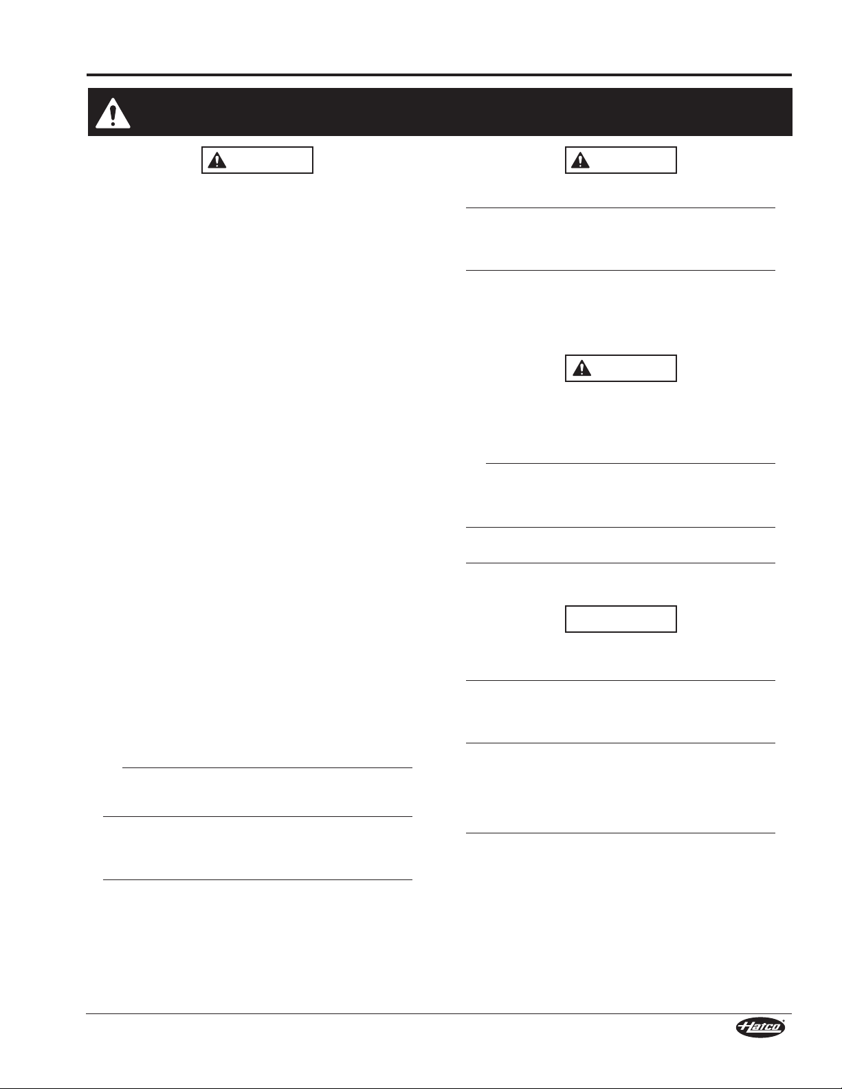
4" (102 mm)
Swivel Caster
4" (102 mm)
Caster
POWER ON/OFF (I/O)
Switch
Glass
Access
Door
F S H C - 5 W 1 - E E
Flav-R-Savor
Holding Cabinet
Number of Shelves
Wide Cabinet Capacity
Energy Efficient
Number of Doors
The Flav-R-Savor®Portable Holding Cabinet is constructed of
sturdy stainless steel. It features electronically-controlled heat,
low velocity convected air, a humidity system, and a heavy-duty,
insulated, glass access door. The access door can be hinged
left or right, depending on the application. The digital
temperature controller is easily accessible. The POWER
ON/OFF (I/O) switch features a safety cover. The unit is made
portable by using 4″ (102 mm) casters—the front two being
swivel casters with wheel locks. Units come standard in
Designer black, are available in optional stainless steel. An
attached 6′ (1829 mm) power cord and plug is standard.
The interior of the cabinet is equipped with five pairs of
adjustable, stainless steel pan slides. These pan slides are
designed to hold full size sheet pans, several steam table pan
sizes (full, half, and third), and Gastronorm pans.
Flav-R-Savor Portable Holding Cabinet (36" [914 mm] Top)
MODEL DESIGNATION
4
Form No. FSHC5WM-0415
Page 5
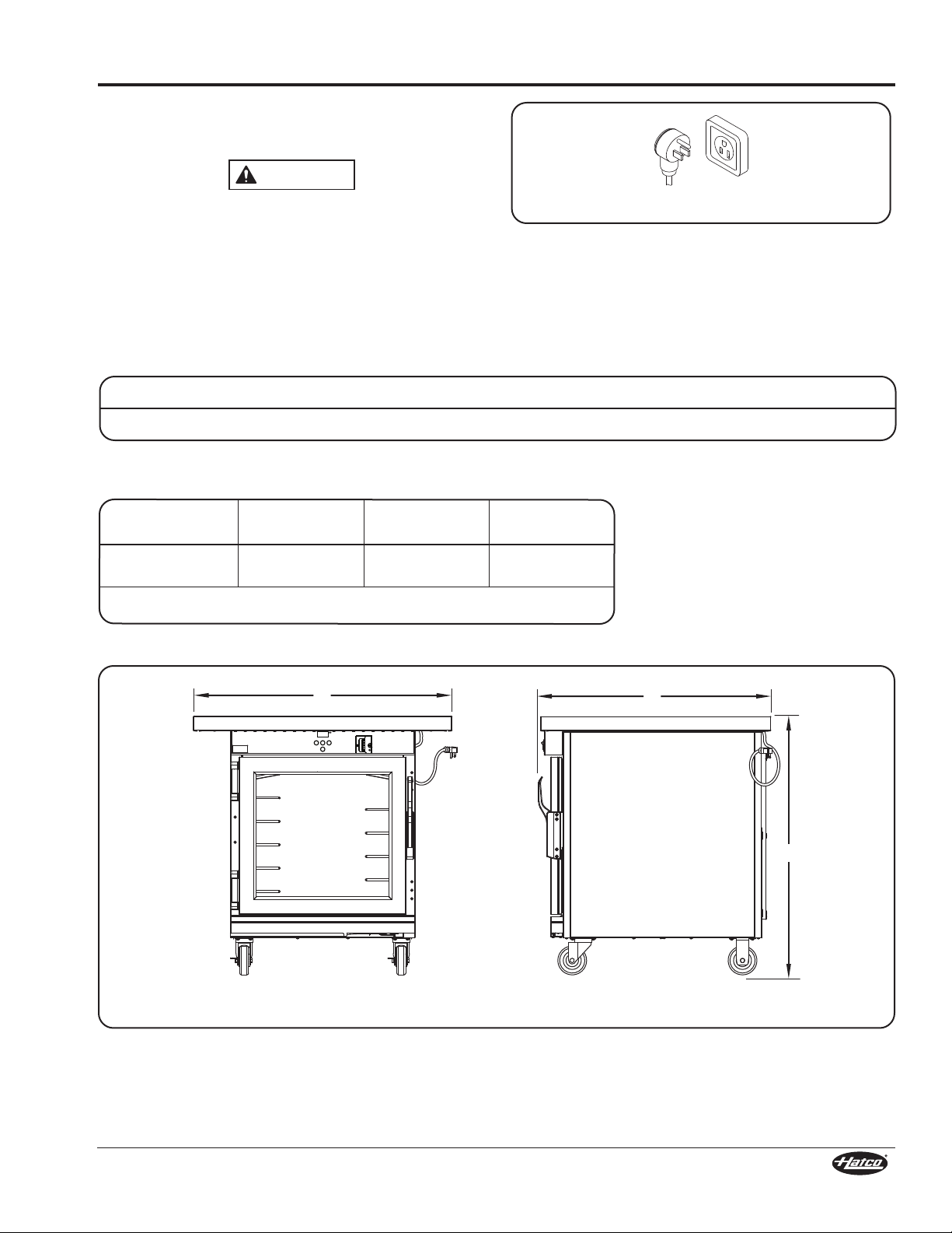
SPECIFICATIONS
WARNING
A
B
C
Front View Side View
F
NEMA 5-15P
Plug Configuration
Units are supplied from the factory with an electrical cord and
plug installed.
ELECTRIC SHOCK HAZARD: Plug unit into a properly
grounded electrical receptacle of the correct voltage, size,
and plug configuration. If the plug and receptacle do not
match, contact a qualified electrician to determine and
install the proper voltage and size electrical receptacle.
NOTE: The specification label is located on the back of the unit.
See label for serial number and verification of unit
electrical information.
NOTE: Receptacle not supplied by Hatco.
Electrical Rating Chart
Model Humidified Voltage Watts Amps Hertz Plug Configuration Shipping Weight
FSHC-5W1-EE Yes 120 1118 9.3 60 NEMA 5-15P 250 lbs. (113 kg)
Dimensions
Plug Configuration
Width
Model
FSHC-5W1-EE
Interior Capacity: 20-15/16" W x 26-5/8" D x 18-3/16" H (532 x 676 x 462 mm)
* Also available in 26" (661 mm) and 32" (813 mm) width.
(A)*
36″
(914 mm)
Depth
(B)
32-3/8″
(821 mm)
Height
(C)
36″
(914 mm)
Form No. FSHC5WM-0415
5
Page 6

INSTALLATION
WARNING
CAUTION
NOTICE
Adjustable Pan Slide
Drip Tray
Built-In Water Reservoir
Drain Hose and Valve
Reservoir Cover
Swivel Caster
Mounting Screw
Angle pan slide
hook into slot and
rotate pan slide down.
Front
Shelf Support
Slot
General
The Flav-R-Savor Portable Holding Cabinet is shipped with
most components installed and ready for operation. The
following installation instructions must be performed before
plugging in and operating the cabinet.
ELECTRIC SHOCK HAZARD: Unit is not weatherproof.
Locate the unit indoors where the ambient air temperature
is a minimum of 70°F (21°C).
FIRE HAZARD: Locate unit a minimum of 1″ (25 mm) from
combustible walls and materials. If safe distances are not
maintained, combustion or discoloration could occur.
Locate unit in an area that is convenient for use. The
location should be level to prevent unit or its contents from
falling accidentally and strong enough to support the
weight of the unit and contents.
1. Remove the unit from the carton.
2. Remove all loose items shipped inside the cabinet such as
the box containing the adjustable pan slides, the casters,
etc...
NOTE: To prevent delay in obtaining warranty coverage,
complete online warranty registration. See the
IMPORTANT OWNER INFORMATION section for
details.
3. Remove tape and protective packaging from all surfaces of
the unit.
4. Install the 4″ (102 mm) casters onto the bottom of the cabinet.
Do not lay unit on side with control panel or damage to unit
could occur. Make sure all water is drained prior to laying
unit on its side.
a. Carefully lay the unit on its back side. This step requires
two people.
NOTE: Place a piece of cardboard between the cabinet and the
floor to prevent marring the cabinet finish.
b. Install the two swivel casters to the front of the unit using
mounting screws (provided). Tighten securely.
c. Install the two stationary casters to the back of the unit
using mounting screws (provided). Tighten securely.
d. Return the unit to its upright position. This step requires
two people.
5. Unpack the adjustable pan slides from the box and install
them inside the cabinet. There are ten adjustable pan
slides—five on each side of the cabinet. Four shelf
supports, two on each side of the cabinet, support the pan
slides.
To install each pan slide:
a. Align the hooks at each end of the pan slide with the
desired slots on the front and rear shelf supports.
b. Angle the pan slide hooks into the slots and let the pan
slide rotate down into position.
6. Place the reservoir cover over the built-in water reservoir.
Installing the Components
6
Form No. FSHC5WM-0415
Page 7

7. Place the unit in the desired location.
Adjustable
Top Shelf
Screw
Strike plate screw plugs
moved to these holes.
Hinge screw plugs
moved to these holes
(top and bottom).
Strike
Plate
Hinge Cover
Hinge Screw
Glass Access
Door
Handle
Screw
Strike Plate
Screw
• Locate the unit in an area where the ambient air
temperature is constant and a minimum of 70°F (21°C).
Avoid areas that may be subject to active air movements
or currents (i.e., near exhaust fans/hoods and air
conditioning ducts).
• Make sure the unit is located on solid, level flooring.
• Make sure the unit is at the proper height in an area
convenient for use.
Adjusting the Top Shelf (Side to Side)
The top shelf of the unit can be adjusted from side to side in 1"
(25 mm) increments. Use the following procedure to adjust the
top shelf.
1. Remove the two screws holding the top shelf in place.
2. Move the top shelf to either side until it is in the desired
location.
3. Make sure the screw holes on the top shelf align with the
screw holes on the unit. Install the screws into place.
Tighten securely.
INSTALLATION
Removing the Access Door
5. Remove the two strike plate screws that secure the strike
plate to the cabinet.
6. Transfer the screw plugs from the strike plate holes on the
opposite side of the cabinet to the open holes where the
strike plate was just removed.
7. Install the strike plate on the opposite side of the cabinet
using the original hardware.
8. Rotate the door 180° and install on the opposite side of
cabinet using the original hardware.
9. Install the handle to the door in the upright position using
the original hardware.
10. Slide the hinge covers back into place on the door hinges.
Reversing the Access Door
The access door is field reversible to allow it to be hinged on
either the right or left side. Use the following procedure to
reverse the door.
1. Remove the four handle screws securing the handle to the
2. Slide the hinge covers off of the door hinges.
3. At each door hinge, remove the three hinge screws that
NOTE: The hinges remain mounted to the access door.
4. Transfer the screw plugs from the hinge screw holes on
Form No. FSHC5WM-0415
Adjusting the Top Shelf
door. Remove the handle.
secure the hinges to the cabinet frame. Remove the
access door.
the opposite side of the cabinet to the open holes where
the hinges were just removed.
Reversing and Installing the Access Door
7
Page 8

OPERATION
WARNING
NOTICE
CAUTION
Water
Reservoir
Fill Line
CAUTION
POWER ON/OFF (I/O) Switch
Digital Temperature
Controller
WARNING
General
Use the following procedures to operate a Flav-R-Savor
Portable Holding Cabinet.
Read all safety messages in the IMPORTANT SAFETY
INFORMATION section before operating this equipment.
Startup
1. Plug the unit into a properly grounded electrical receptacle
of the correct voltage, size, and plug configuration. See the
SPECIFICATIONS section for details.
Use of distilled water in water reservoir of humidified units
is recommended. If non-distilled water is used, reservoir
will require periodic cleaning and deliming (refer to
MAINTENANCE section for cleaning procedure). Product
failure caused by liming or sediment buildup is not covered
under warranty.
2. Fill the built-in water
reservoir with distilled water.
To fill the water reservoir:
a. Open the access door.
b. Remove the reservoir
cover.
c. Slowly pour water into
the water reservoir until
the water level reaches
the fill line on the back
of the reservoir. Do not
fill water above this line.
d. Replace the reservoir cover.
e. Close the access door.
NOTE: Clean the water reservoir daily to extend the life of the
electrical and mechanical components and to keep
cleaning easy. If “hard” water is used, the reservoir will
require periodic cleaning and de-liming. Refer to the
MAINTENANCE section for de-liming instructions.
Do not overfill water pan. Overfilling can cause water to
leak onto floor and create a slipping hazard.
NOTE: The capacity of the water reservoir is approximately four
(4) quarts (3.8 liters).
3. Move the POWER ON/OFF (I/O) switch to the ON (I) position.
• The heating system will start up.
• The CABINET TEMPERATURE display will show the
current temperature of the cabinet or “LO”. “LO”
indicates the cabinet temperature is below 70°F (21°C).
BURN HAZARD: Some exterior surfaces on the unit will get
hot. Use caution when touching these areas.
4. Set the air temperature to 180°F (82°C). Refer to the
“Setting the Air Temperature” procedure in this section for
more information.
5. Set the humidity to level 1. Refer to the “Setting the
®
Humidity Level” procedure in this section for more
information.
Controls
6. Allow 30 minutes to preheat the cabinet with a full pan of
water before loading preheated food product. The unit is
ready when the CABINET TEMPERATURE display shows
180°F (82°C) as the temperature.
7. Place a sheet pan and wire rack OR a full size 2" deep
stainless steel pan with a wire rack on the center shelf.
• Place additional pans and racks on the racks starting
from the top and moving to the bottom. No more than
three pans should be used in the cabinet at a time.
8. Place cooked and drained chicken on the wire rack bone
side down.
• Chicken may be held for up to 3 hours and must maintain
an internal temperature of 165°F (74°C).
9. If chicken is not sold within 3 hours, place chicken in an
individual container with label and date (do not cover until
cool). Store in refrigerator.
• Do not store warm chicken with cooled chicken.
• Use chicken within 48 hours or discard.
10. If refrigerated chicken is unused within 48 hours, place
chicken in freezer until needed. This requires a 24 hour
thaw time.
Make sure food product has been heated to the proper
food-safe temperature before placing in unit. Failure to heat
food product properly may result in serious health risks.
This unit is for holding pre-heated food product only.
Shutdown
1. Move the POWER ON/OFF (I/O) Switch to the OFF (O)
position and allow the unit to cool.
2. Perform the “Daily Cleaning” procedure in the
MAINTENANCE section of this manual.
8
Form No. FSHC5WM-0415
Page 9

OPERATION
Setting the Air Temperature
Use the following procedure to set or change the air
temperature.
1. Press the key to enter temperature mode (“tSP” will
appear on the CABINET TEMPERATURE display).
2. Press the key again to show the current temperature
setting.
3. Press the key or key to reach the desired
temperature. The temperature range is 80°–200°F
(27°–93°C) in single degree increments. Culver’s
recommends 180°F (82°C) for this unit.
4. After the desired temperature is set, wait 15 seconds
without pushing any keys for the cabinet temperature
display to return automatically to operational mode.
Setting the Humidity Level
Use the following procedure to set the humidity level on
humidified units.
1. Press the key to enter humidity mode (“hSP” will
appear on the CABINET TEMPERATURE display).
2. Press the key again to show the current humidity level.
3. Press the key or key to reach the desired humidity
level. Humidity range is 0 through 5 (0 is the lowest amount
of humidity and 5 is the highest). Culver’s recommends
humidity level 1 for this unit.
Setting the Humidity Level
4. After the desired humidity level is set, wait 15 seconds
without pushing any keys for the cabinet temperature
display to return automatically to operational mode.
Setting the Air Temperature
NOTE: Temperature and humidity settings may vary depending
upon product make-up and consistency. The CABINET
TEMPERATURE display shows the lowest temperature
point inside the cabinet, not the product temperature.
The capacity of the water reservoir permits uninterrupted
operation for approximately 7–9 hours, depending on the
settings and how frequently the door is opened. Check the
water level in the reservoir regularly, and re-fill when necessary.
The water reservoir refill capacity is approximately four (4)
quarts (3.8 liters). WARNING! Electric Shock Hazard — Do
not overfill water reservoir.
Food Holding Guide
Type of Food
Biscuits 4 Hours 3 140 60
Chicken Pieces (Fried) 4 Hours 1 170 77
Croissants 4 Hours 1 140 60
Fruit Pies 3-1/2 Hours 3 140 60
Onion Rings 1/2 to 2 Hours 1 180 82
Pizza — Thick Crust
Thin Crust
Maximum
Holding Time
1 Hour
1 Hour
Humidity
Setting
1
2
Air Temperature Setting
°F °C
185
180
85
82
Pretzels 3 Hours 3 140 60
Wrapped Sandwiches 2 Hours 3 170 77
NOTE: All times and settings are recommendations only and may vary depending on product preparation, cooking time, and
Form No. FSHC5WM-0415
internal food temperature.
9
Page 10

MAINTENANCE
WARNING
WARNING
NOTICE
Drip Tray
Hose Valve
(closed position)
Hose Valve
(closed position)
Drain
Hose
General
The Flav-R-Savor Portable Holding Cabinet is designed for
maximum durability and performance with minimum
maintenance.
ELECTRIC SHOCK HAZARD:
• Turn OFF power switch, unplug power cord, and allow
unit to cool before performing any cleaning,
adjustments, or maintenance.
• DO NOT submerge or saturate with water. Unit is not
waterproof. Do not operate if unit has been submerged
or saturated with water.
• Unit is not weatherproof. Locate unit indoors where
ambient air temperature is a minimum of 70°F (21°C).
• This unit is not “jet-proof” construction. Do not use jetclean spray to clean this unit.
• Do not steam clean or use excessive water on unit.
• Do not clean unit when it is energized or hot.
• This unit must be serviced by qualified personnel only.
Service by unqualified personnel may lead to electric
shock or burn.
This unit has no “user-serviceable” parts. If service is
required on this unit, contact an Authorized Hatco Service
Agent or contact the Hatco Service Department at
800-558-0607 or 414-671-6350; fax 800-690-2966; or
International fax 414-671-3976.
NOTE: The internal blower motor is permanently lubricated and
requires no maintenance.
Daily Cleaning
To preserve the finish of the unit as well as maintain
performance, it is recommended that the unit be cleaned daily.
ELECTRIC SHOCK HAZARD: Turn OFF power switch,
unplug power cord, and allow unit to cool before
performing any cleaning, adjustments, or maintenance.
6. Flush the water reservoir with fresh water.
7. Wipe the interior of the water reservoir until it is dry with a
clean, non-abrasive cloth.
8. Squeeze the hose valve to close the drain hose.
NOTE: If the water used has an excessive amount of lime or
mineral content, follow the “Removing Lime and Mineral
Deposits” procedure for periodic cleaning and deliming
of the water reservoir. Unit failure caused by liming or
sediment buildup is not covered under warranty.
Draining the Water Reservoir
9. Wipe down all the interior and the exterior surfaces using
a clean, damp cloth. Stubborn stains may be removed with
a good non-abrasive cleaner. Hard to reach areas should
be cleaned with a small brush and mild soap.
10. Wipe dry with a clean, non-abrasive cloth.
Use non-abrasive cleaners and cloths only. Abrasive
cleaners and cloths could scratch finish of unit, marring
its appearance and making it susceptible to soil
accumulation.
Clean unit daily to avoid malfunctions and maintain sanitary
operation.
1. Move the POWER ON/OFF (I/O) switch to the OFF (O)
position, unplug power cord, and allow the unit to cool.
2. Remove and wash all food pans.
3. Locate the drain hose with hose valve near the bottom,
right side of the cabinet underneath the drip tray.
CAUTION! Burn Hazard—Water in reservoir is hot
during operation. Allow to cool before draining.
4. Position a 2-1/2″ (64 mm) deep, full size food pan under
the drain stopper to catch draining water.
5. Unlatch the hose valve to open the drain hose and empty
the reservoir.
10
Form No. FSHC5WM-0415
Page 11

Removing Lime and Mineral Deposits
NOTICE
Use the following procedure for periodic cleaning and deliming
of the water reservoir on humidified models.
Use of distilled water in water reservoir of humidified units
is recommended. If non-distilled water is used, reservoir
will require periodic cleaning and deliming. Product failure
caused by liming or sediment buildup is not covered under
warranty.
NOTE: The lime and mineral content of the water used for daily
operation will determine how often the deliming
procedure must be performed.
NOTE: Perform this procedure when the unit will not be used
for a period of time, such as the end of the day.
(Recommended monthly)
1. Move the POWER ON/OFF (I/O) switch to the OFF (O)
position. Allow the unit to cool.
2. Remove and wash all food pans.
3. Remove the reservoir cover.
4. Fill the water reservoir with a mixture of 75% water and
25% white vinegar. Do not use flavored vinegar.
5. Replace the reservoir cover.
6. Turn on the unit.
7. Set both the air temperature and humidity level to their
highest settings and allow the unit to run for 30 minutes.
8. Move the POWER ON/OFF (I/O) switch to the OFF (O)
position, unplug power cord, and allow the unit to cool.
9. Drain the vinegar mixture and rinse reservoir thoroughly.
10. Continue to fill and drain the water reservoir with clean
water until the deliming solution is rinsed through and the
reservoir is clean.
11. After the unit has cooled down, perform the “Daily
Cleaning” procedure in this section.
12. Plug the unit into its power source and fill the reservoir as
usual for daily operation. Refer to the procedure in the
OPERATION section of this manual.
MAINTENANCE
Form No. FSHC5WM-0415
11
Page 12

TROUBLESHOOTING GUIDE
WARNING
WARNING
This unit must be serviced by trained and qualified
personnel only. Service by unqualified personnel may lead
to electric shock or burn.
Symptom Probable Cause Corrective Action
Unit is plugged in, but nothing
works.
Unit operates, but is not circulating
air inside cabinet.
Unit not turned on. Move POWER ON/OFF (I/O) switch to the ON
No power to unit. Check electrical receptacle and verify that
Power cord connections are loose or
disconnected.
Power cord is damaged. Contact Authorized Service Agent or Hatco for
Defective POWER ON/OFF (I/O) switch. Contact Authorized Service Agent or Hatco for
Defective digital temperature controller. Contact Authorized Service Agent or Hatco for
Blower motor defective. Contact Authorized Service Agent or Hatco for
Incorrect voltage supplied to blower motor. Contact Authorized Service Agent or Hatco for
ELECTRIC SHOCK HAZARD: Turn OFF power switch,
unplug power cord, and allow unit to cool before
performing any cleaning, adjustments, or maintenance.
(I) position.
power supply matches specifications on unit. If
receptacle is not working, check circuit breaker
and reset, or plug unit into a different known
working receptacle.
Contact Authorized Service Agent or Hatco for
assistance.
assistance.
assistance.
assistance.
assistance.
assistance.
Unit is leaking. The hose valve is not tight enough. Tighten drain hose by squeezing the hose
Unit is not producing any “hot air”
inside cabinet.
Unit is heating, but is not producing
humidity inside cabinet.
Error Codes
The following error codes may appear on the CABINET
TEMPERATURE display to indicate an error in the operating
condition of the unit.
E1 = Air temperature sensor malfunctioning. Contact Authorized
Service Agent or Hatco for assistance.
E2 = Humidity sensor malfunctioning. Contact Authorized
Service Agent or Hatco for assistance.
Safety high-limit is tripped or open. Contact Authorized Service Agent or Hatco for
Incorrect voltage supplied to heating
element.
Blower motor not working. Contact Authorized Service Agent or Hatco for
Air heating element(s) defective. Contact Authorized Service Agent or Hatco for
Water reservoir is empty. Fill water reservoir with clean water.
Humidity is set too low. Increase humidity level. Refer to “Setting the
Incorrect voltage supplied to water heating
element or heating element defective.
Troubleshooting Questions?
If you continue to have problems resolving an issue, please
contact the nearest Authorized Hatco Service Agency or Hatco
for assistance. To locate the nearest Service Agency, log onto
the Hatco website at www.hatcocorp.com and click on
Find Service Agent, or contact the Hatco Parts and Service
Team at:
Telephone: 800-558-0607 or 414-671-6350
e-mail: partsandservice@hatcocorp.com
Fax: 800-690-2966 or 414-671-3976
valve.
assistance.
Contact Authorized Service Agent or Hatco for
assistance.
assistance.
assistance.
Humidity Level” in the OPERATION section.
Contact Authorized Service Agent or Hatco for
assistance.
12
Form No. FSHC5WM-0415
Page 13

LIMITED WARRANTY
1. PRODUCT WARRANTY
Hatco warrants the products that it manufactures (the
“Products”) to be free from defects in materials and
workmanship, under normal use and service, for a period of
one (1) year from the date of purchase when installed and
maintained in accordance with Hatco’s written instructions or
18 months from the date of shipment from Hatco. Buyer must
establish the Product’s purchase date by registering the Product
with Hatco or by other means satisfactory to Hatco in its sole
discretion.
Hatco warrants the following Product components to be free
from defects in materials and workmanship from the date of
purchase (subject to the foregoing conditions) for the period(s)
of time and on the conditions listed below:
a) One (1) Year Parts and Labor PLUS One (1) Additional
Year Parts-Only Warranty:
Conveyor Toaster Elements (metal sheathed)
Drawer Warmer Elements (metal sheathed)
Drawer Warmer Drawer Rollers and Slides
Strip Heater Elements (metal sheathed)
Display Warmer Elements (metal sheathed air heating)
Holding Cabinet Elements (metal sheathed air heating)
Heated Well Elements — HW and HWB Series
(metal sheathed)
b) One (1) Year Parts and Labor PLUS Four (4) Years
Parts-Only Warranty:
3CS and FR Tanks
c) One (1) Year Parts and Labor PLUS Nine (9) Years
Parts-Only Warranty on:
Electric Booster Heater Tanks
Gas Booster Heater Tanks
d) Ninety (90) Day Parts-Only Warranty:
Replacement Parts
THE FOREGOING WARRANTIES ARE EXCLUSIVE AND IN
LIEU OF ANY OTHER WARRANTY, EXPRESSED OR
IMPLIED, INCLUDING BUT NOT LIMITED TO ANY IMPLIED
WARRANTY OF MERCHANTABILITY OR FITNESS FOR A
PARTICULAR PURPOSE OR PATENT OR OTHER
INTELLECTUAL PROPERTY RIGHT INFRINGEMENT.
Without limiting the generality of the foregoing, SUCH
WARRANTIES DO NOT COVER: Coated incandescent light
bulbs, fluorescent lights, heat lamp bulbs, coated halogen light
bulbs, halogen heat lamp bulbs, xenon light bulbs, LED light
tubes, glass components, and fuses; Product failure in booster
tank, fin tube heat exchanger, or other water heating equipment
caused by liming, sediment buildup, chemical attack, or
freezing; or Product misuse, tampering or misapplication,
improper installation, or application of improper voltage.
2. LIMITATION OF REMEDIES AND DAMAGES
Hatco’s liability and Buyer’s exclusive remedy hereunder will be
limited solely, at Hatco’s option, to repair or replacement using
new or refurbished parts or Product by Hatco or a Hatcoauthorized service agency (other than where Buyer is located
outside of the United States, Canada, United Kingdom, or
Australia, in which case Hatco’s liability and Buyer’s exclusive
remedy hereunder will be limited solely to replacement of part
under warranty) with respect to any claim made within the
applicable warranty period referred to above. Hatco reserves
the right to accept or reject any such claim in whole or in part.
In the context of this Limited Warranty, “refurbished” means a
part or Product that has been returned to its original
specifications by Hatco or a Hatco-authorized service agency.
Hatco will not accept the return of any Product without prior
written approval from Hatco, and all such approved returns shall
be made at Buyer’s sole expense. HATCO WILL NOT BE
LIABLE, UNDER ANY CIRCUMSTANCES, FOR
CONSEQUENTIAL OR INCIDENTAL DAMAGES, INCLUDING
BUT NOT LIMITED TO LABOR COSTS OR LOST PROFITS
RESULTING FROM THE USE OF OR INABILITY TO USE THE
PRODUCTS OR FROM THE PRODUCTS BEING
INCORPORATED IN OR BECOMING A COMPONENT OF
ANY OTHER PRODUCT OR GOODS.
Form No. FSHC5WM-0415
13
Page 14

REPLACEMENT PARTS LIST
7
5
8
1
4
2
3
9
10
12
11
17
14
19
16
15
18
29
32
31
30
23
33
34
35
36
27
26
23
24
25
22
21
20
Specification Label on
underside of top shelf.
13
28
6
Hatco Flav-R-Savor®Portable Holding Cabinet
FSHC-5W Series
14
Form No. FSHC5WM-0415
Page 15

REPLACEMENT PARTS LIST
CAUTION
Week Fifty-One
0951
Year 2009
24 Hour 7 Day Parts and Service
Assistance available in the United States
and Canada by calling 800-558-0607.
Item Description Part No. Qty.
1 Top
36" Countertop 04.48.782.00 1
32" Countertop 04.48.785.00 1
25-3/4" Top 04.48.876.01 1
2 Blower Motor and Blower Blade R02.12.117.00 1
3 Blower Blade 02.12.065.00 1
4 Shelf Support Frame 04.48.772.00 4
5 Control Panel Label 07.01.370.00 1
6 Switch Guard, Rocker 04.48.975.00 1
7 Switch, Rocker 02.19.015.00 1
8 Hinge 04.26.002.00 2
9 Door Assembly † R00.01.0141.00 1
10 Handle 05.30.113.00 1
11 Door Gasket 05.06.147.00 1
12 Pan Slide 04.48.364.00 10
13 Cover, Reservoir 04.48.919.00 1
14 Thumbscrew 05.04.708.00 8
15 Pipe Nipple, 3/8" 03.11.003.00 1
16 Tee, 3/8" 03.05.122.00 1
17 Hose Clamp, 1/2" 05.04.550.00 3
18 Drip Tray Skirt 04.48.748.00 1
Item Description Part No. Qty.
19 Blanket Element, 300 W, 120 V 02.05.738.00 1
20 Air Element, 400 W, 120 V 02.08.647.01 2
21 Thermostat, Electronic R02.01.273.00 1
22 Transformer, 120–24 V 02.17.022.00 1
23 Thermistor Probe 02.01.203.00 2
24 Surface High Limit, Upper R02.16.118.00 1
25 Terminal Block R02.15.046.00 1
26 Cord Grip, Straight R02.20.259.00 1
27 Power Cord, Right Angle R02.18.130.00 1
28 Splash Guard 04.48.974.00 1
29 Drip Tray Assembly 04.48.562.00 1
30 Tubing * 03.40.146.00 1’
31 Drain Clamp 03.02.085.00 1
32 Drip Tray Skirt Cover 04.48.750.00 1
33 Bracket, Probe 04.48.728.00 1
34 Surface High Limit, Lower R02.16.036.00 1
35 Caster, 4", Rigid 04.26.003.00 2
36 Caster, 4", Swivel 04.26.004.00 2
Wiring Diagram 10-01-1008
† Includes Items 8, 10, and 11.
* Sold by the foot.
NOTE: The last four digits in a ten digit numerical serial number are the manufacturing date code.
Example: Serial number 9625060951 has a date code of “0951” which indicates the following:
Use of replacement parts other than those supplied by
Hatco Corporation may result in damage to the unit or
injury to personnel and will void all warranties.
Form No. FSHC5WM-0415
15
Page 16

HATCO CORPORATION
P.O. Box 340500
Milwaukee, WI 53234-0500 U.S.A.
800-558-0607 414-671-6350
Parts and Service Fax 800-690-2966
International Fax 414-671-3976
partsandservice@hatcocorp.com
www.hatcocorp.com
AUTHORIZED PARTS DISTRIBUTORS • AUTORISÉS DISTRIBUTEURS DE PIÈCES
LABAMA
A
Jones McLeod Appl. Svc.
Birmingham 205-251-0159
ARIZONA
Service Solutions Group
Phoenix 602-234-2443
Byassee Equipment Co.
Phoenix 602-252-0402
CALIFORNIA
ndustrial Electric
I
ommercial Parts & Service, Inc.
C
untington Beach 714-379-7100
H
Chapman Appl. Service
San Diego 619-298-7106
P & D Appliance
Commercial Parts & Service, Inc.
S. San Francisco 650-635-1900
COLORADO
awkins Commercial Appliance
H
nglewood 303-781-5548
E
FLORIDA
Whaley Foodservice Repair
Jacksonville 904-725-7800
Wire Nass Service Co., Inc.
3
rlando 407-425-2681
O
B.G.S.I.
Pompano Beach 954-971-0456
Comm. Appliance Service
Tampa 813-663-0313
GEORGIA
TWC Services
Mableton 770-438-9797
Heritage Service Group
Norcross 866-388-9837
Southeastern Rest. Svc.
Norcross 770-446-6177
HAWAII
Burney’s Comm. Service, Inc.
Honolulu 808-848-1466
Food Equip Parts & Service
Honolulu 808-847-4871
ILLINOIS
Parts Town
Lombard 708-865-7278
Eichenauer Elec. Service
Decatur 217-429-4229
Midwest Elec. Appl. Service
Elmhurst 630-279-8000
Cone’s Repair Service
Moline 309-797-5323
INDIANA
GCS Service
Indianapolis 800-727-8710
IOWA
oodwin Tucker Group
G
es Moines 515-262-9308
D
ENTUCKY
K
Service Solutions Group
Lexington 859-254-8854
Service Solutions Group
Louisville 502-451-5411
LOUISIANA
handlers Parts & Service
C
aton Rouge 225-272-6620
B
MARYLAND
Electric Motor Service
Baltimore 410-467-8080
GCS Service
Silver Spring 301-585-7550
MASSACHUSETTS
Ace Service Co., Inc.
eedham 781-449-4220
N
ICHIGAN
M
Bildons Appliance Service
Detroit 248-478-3320
Commercial Kitchen Service
Bay City 989-893-4561
Midwest Food Equip. Service
Grandville 616-261-2000
MINNESOTA
CS Service
G
innetonka 800-822-2303
M
MISSOURI
General Parts
Kansas City 816-421-5400
Commercial Kitchen Services
St. Louis 314-890-0700
Kaemmerlen Parts & Service
St. Louis 314-535-2222
NEBRASKA
Anderson Electric
Omaha 402-341-1414
NEVADA
Burney’s Commercial
Las Vegas 702-736-0006
Hi. Tech Commercial Service
N. Las Vegas 702-649-4616
NEW JERSEY
Jay Hill Repair
Fairfield 973-575-9145
Service Plus
Flanders 973-691-6300
x20365
EW YORK
N
Acme American Repairs, Inc.
Brooklyn 718-456-6544
Alpro Service Co.
Brooklyn 718-386-2515
Appliance Installation
Buffalo 716-884-7425
uffy’s Equipment Services, Inc.
D
uffalo 800-836-1014
B
Wire Northern
3
lattsburgh 800-634-5005
P
Duffy’s Equipment Services, Inc.
Sauquoit 800-836-1014
J.B. Brady, Inc.
Syracuse 315-422-9271
NORTH CAROLINA
uthorized Appliance
A
harlotte 704-377-4501
C
OHIO
Akron/Canton Comm. Svc. Inc.
Akron 330-753-6634
Service Solutions Group
Cincinnati 513-772-6600
Commercial Parts and Service
Columbus 614-221-0057
Electrical Appl. Repair Service
Brooklyn Heights 216-459-8700
. A. Wichman Co.
E
oledo 419-385-9121
T
OKLAHOMA
Hagar Rest. Service, Inc.
Oklahoma City 405-235-2184
Krueger, Inc.
Oklahoma City 405-528-8883
OREGON
Ron’s Service, Inc.
Portland 503-624-0890
PENNSYLVANIA
Elmer Schultz Services
Philadelphia 215-627-5401
FAST Comm. Appl. Service
Philadelphia 215-288-4800
Appliance Installation & Service
Pittsburgh 412-809-0244
K & D Service Co.
Harrisburg 717-236-9039
Electric Repair Co.
Reading 610-376-5444
RHODE ISLAND
Marshall Electric Co.
Providence 401-331-1163
SOUTH CAROLINA
Whaley Foodservice Repair
Lexington 803-996-9900
TENNESSEE
Camp Electric
Memphis 901-527-7543
EXAS
T
GCS Service
Fort Worth 800-433-1804
Armstrong Repair Service
Houston 713-666-7100
Cooking Equipment Specialist
Mesquite 972-686-6666
ommercial Kitchen Repair Co.
C
an Antonio 210-735-2811
S
UTAH
a Monica’s Rest. Equip. Service
L
urray 801-263-3221
M
IRGINIA
V
Daubers
Norfolk 757-855-4097
Daubers
Springfield 703-866-3600
WASHINGTON
Wire Restaurant Appliance
3
eattle 800-207-3146
S
WISCONSIN
A.S.C., Inc.
Madison 608-246-3160
A.S.C., Inc.
Milwaukee 414-543-6460
CANADA
ALBERTA
Key Food Equipment Service
Edmonton 780-438-1690
BRITISH COLUMBIA
Key Food Equipment Service
Vancouver 604-433-4484
Key Food Equipment Service
Victoria 250-920-4888
MANITOBA
Air Rite, Inc.
Winnipeg 204-895-2300
NEW BRUNSWICK
EMR Services, Ltd.
Moncton 506-855-4228
ONTARIO
R.G. Henderson Ltd.
Toronto 416-422-5580
Choquette - CKS, Inc.
Ottawa 613-739-8458
QUÉBEC
Choquette - CKS, Inc.
Montreal 514-722-2000
Choquette - CKS, Inc.
Québec City 418-681-3944
UNITED KINGDOM
Marren Group
Northants +44(0)1933 665313
Printed in U.S.A. April 2015
Register your unit online!
See IMPORTANT OWNER INFORMATION
section for details.
P/N 07.04.627.00 Form No. FSHC5WM-0415
 Loading...