

Page 1
hatcocorp.com
ADVERTENCIA
Register Online!
(see page 2)
S’inscrire en ligne!
(voir page 19)
®
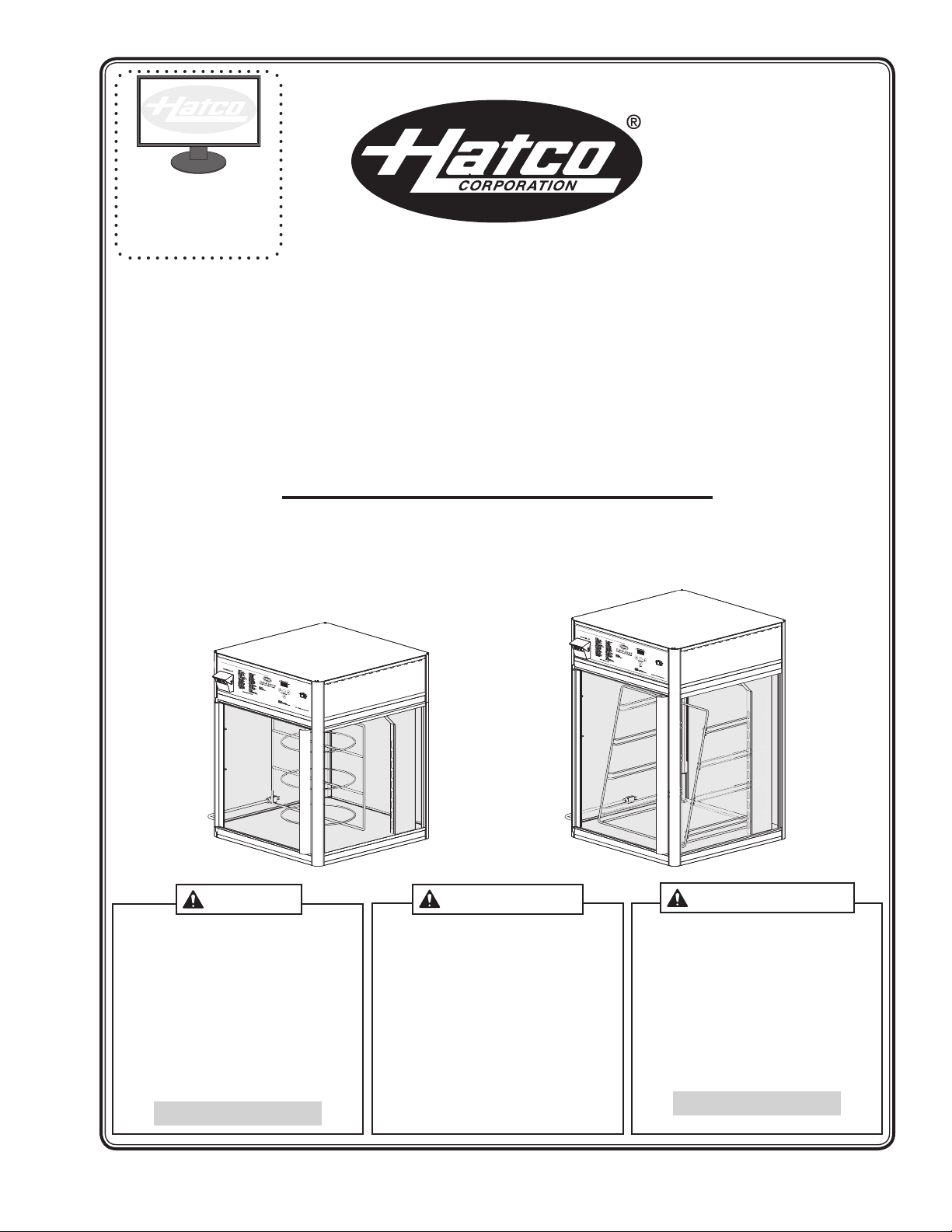
Flav-R-Savor
Humidied Holding and Display Cabinets
Armoires d’exposition et de conservation
avec ajout d’humidité
FSD and FSDT Series/Série
Installation and Operating Manual
Manuel d’installation et d’utilisation
WARNING
Do not operate this equipment unless you
have read and understood the contents
of this manual! Failure to follow the
instructions contained in this manual
may result in serious injury or death.
This manual contains important safety
information concerning the maintenance,
use, and operation of this product. If
you’re unable to understand the contents
of this manual, please bring it to the
attention of your supervisor. Keep this
manual in a safe location for future
reference.
English = p 2
No opere este equipo al menos que haya
leído y comprendido el contenido de este
manual! Cualquier falla en el seguimiento
de las instrucciones contenidas en
este manual puede resultar en un serio
lesión o muerte. Este manual contiene
importante información sobre seguridad
concerniente al mantenimiento, uso y
operación de este producto. Si usted
no puede entender el contenido de
este manual por favor pregunte a su
supervisor. Almacenar este manual en
una localización segura para la referencia
futura.
AVERTISSEMENT
Ne pas utiliser cet équipement sans avoir
lu et compris le contenu de ce manuel ! Le
non-respect des instructions contenues
dans ce manuel peut entraîner de
graves blessures ou la mort. Ce manuel
contient des informations importantes
concernant l’entretien, l’utilisation et le
fonctionnement de ce produit. Si vous ne
comprenez pas le contenu de ce manuel,
veuillez le signaler à votre supérieur.
Conservez ce manuel dans un endroit
sûr pour pouvoir vous y référer plus tard.
Français = p 19
P/N 07.04.289.00 © 2019 Hatco Corporation
Page 2
CAUTION
CONTENTS
English
Important Owner Information .............................................. 2
Introduction ...........................................................................2
Important Safety Information .............................................. 3
Model Description ................................................................4
Model Designation ...............................................................4
Specifications ....................................................................... 5
Dimensions .......................................................................... 5
Plug Configurations ............................................................. 5
Electrical Rating Chart ......................................................... 6
Installation .............................................................................7
General ................................................................................ 7
Reversing the Access Door .................................................8
Relocating the Proximity Switch .......................................... 9
Operation .............................................................................10
General .............................................................................. 10
Setting the Air Temperature ............................................... 11
Setting the Humidity Level ................................................. 11
Food Holding Guide .......................................................... 11
IMPORTANT OWNER INFORMATION
Record the model number, serial number, voltage, and
purchase date of the unit in the spaces below (specification
label located on the ceiling sheet inside the unit). Please
have this information available when calling Hatco for service
assistance.
Model No. ________________________________________
Serial No. _________________________________________
Voltage ___________________________________________
Date of Purchase ___________________________________
Register your unit!
Completing online warranty registration will prevent delay in
obtaining warranty coverage. Access the Hatco website at
www.hatcocorp.com, select the Support pull-down menu,
and click on “Warranty”.
Maintenance ........................................................................ 12
General .............................................................................. 12
Daily Cleaning ...................................................................12
Removing the Rotating Rack .............................................12
Removing the Glass Panels .............................................. 12
Draining the Water Reservoir ............................................13
Removing Lime and Mineral Deposits ..............................13
Replacing an LED Light Strip ............................................ 13
Setting the De-Liming Detection Mode .............................14
Troubleshooting Guide ......................................................14
Error Codes .......................................................................15
Options and Accessories .................................................. 15
Limited Warranty ................................................................18
Authorized Parts Distributors ........................... Back Cover
Business
Hours: 7:00 am to 5:00 pm Monday–Friday,
Central Time (CT)
(Summer Hours — June to September:
7:00 am to 5:00 pm Monday–Thursday
7:00 am to 4:00 pm Friday)
Telephone: 800-558-0607; 414-671-6350
E-mail: support@hatcocorp.com
24 Hour 7 Day Parts and Service
Assistance available in the United States
and Canada by calling 800-558-0607.
Additional information can be found by visiting our web site at
www.hatcocorp.com.
INTRODUCTION
Hatco Flav-R-Savor® Humidified Holding and Display Cabinets
are designed to hold prepared foods for prolonged periods
of time while maintaining that “just-made” quality. Hatco
Humidified Holding and Display Cabinets provide the best
environment for food products by regulating the air temperature
while at the same time balancing the humidity level. The use
of controlled moisturized heat maintains serving temperature
and texture longer than conventional dry holding equipment.
Flav-R-Savor air flow pattern is designed to maintain consistent
cabinet temperature without drying out foods. The precise
combination of heat and humidity creates a “blanket” effect
around the food. The air flow rate enables the cabinet to
recover temperature rapidly after opening and closing the door.
Hatco Humidified Holding and Display Cabinets are products
of extensive research and field testing. The materials used
were selected for maximum durability, attractive appearance
and optimum performance. Every unit is inspected and tested
thoroughly prior to shipment.
This manual provides installation, safety, and operating
instructions for Hatco Humidified Holding and Display Cabinets.
Hatco recommends all installation, operating, and safety
instructions appearing in this manual be read prior to installation
or operation of a unit.
Safety information that appears in this manual is identified by
the following signal word panels:
WARNING
WARNING indicates a hazardous situation which, if not
avoided, could result in death or serious injury.
CAUTION indicates a hazardous situation which, if not
avoided, could result in minor or moderate injury.
NOTICE
NOTICE is used to address practices not related to
personal injury.
2
Form No. FSDM-0119
Page 3
English
WARNING
CAUTION
WARNING
IMPORTANT SAFETY INFORMATION
Read the following important safety information before using this equipment to avoid serious
injury or death and to avoid damage to equipment or property.
ELECTRIC SHOCK HAZARD:
• Plug unit into a properly grounded electrical receptacle
of the correct voltage, size, and plug configuration. If
plug and receptacle do not match, contact a qualified
electrician to determine and install proper voltage and
size electrical receptacle.
• Turn OFF power switch, unplug power cord, and
allow unit to cool before performing any cleaning,
adjustments, or maintenance.
• DO NOT submerge or saturate with water. Unit is not
waterproof. Do not operate if unit has been submerged
or saturated with water.
• Unit is not weatherproof. Locate unit indoors where
ambient air temperature is a minimum of 70°F (21°C).
• Do not steam clean or use excessive water on unit.
• Do not overfill water reservoir. Overfilling can cause
electrical shock. Water reservoir is full when “LO H2O”
stops flashing on CABINET TEMPERATURE display.
Stop filling when “LO H2O” stops flashing on display.
• Turn OFF power switch and allow unit to cool before
draining water reservoir.
• Do not pull unit by power cord.
• Discontinue use if power cord is frayed or worn.
• Do not attempt to repair or replace a damaged
power cord. The cord must be replaced by Hatco, an
Authorized Hatco Service Agent, or a person with
similar qualifications.
• This unit must be serviced by qualified personnel only.
Service by unqualified personnel may lead to electric
shock or burn.
• Use only Genuine Hatco Replacement Parts when
service is required. Failure to use Genuine Hatco
Replacement Parts may subject operators of the
equipment to hazardous electrical voltage, resulting in
electrical shock or burn. Genuine Hatco Replacement
Parts are specified to operate safely in the environments
in which they are used. Some aftermarket or generic
replacement parts do not have the characteristics that
will allow them to operate safely in Hatco equipment.
FIRE HAZARD: Locate unit a minimum of 1″ (25 mm) from
combustible walls and materials. If safe distances are not
maintained, discoloration or combustion could occur.
Make sure food product has been heated to the proper
food-safe temperature before placing in unit. Failure to
heat food product properly may result in serious health
risks. This unit is for holding pre-heated food product only.
This unit is not intended for use by children or persons
with reduced physical, sensory, or mental capabilities.
Ensure proper supervision of children and keep them
away from the unit.
Make sure all operators have been instructed on the safe
and proper use of the unit.
Hatco is not responsible for the actual food product
serving temperature. It is the responsibility of the user to
ensure that the food product is held and served at a safe
temperature.
This unit has no “user-serviceable” parts. If service
is required on this unit, contact an Authorized Hatco
Service Agent or contact the Hatco Service Department at
800-558-0607 or 414-671-6350.
BURN HAZARD: Some exterior surfaces on the unit will get
hot. Use caution when touching these areas.
Locate unit at the proper counter height in an area that is
convenient for use. The location should be level to prevent
the unit or its contents from falling accidentally and strong
enough to support the weight of the unit and contents.
The National Sanitation Foundation (NSF) requires that
units over 36″ (914 mm) in width or weighing more than
80 lbs. (36 kg) either be sealed to or raised above the
installation surface. If unit cannot be sealed at the point
of use, 4″ (102 mm) legs are available to allow for proper
cleaning access below unit.
Transport unit in upright position only. Before moving or
tipping unit, secure all glass surfaces with tape and drain
water from water reservoir. Failure to do so may result in
damage to unit or personal injury.
NOTICE
Use of distilled water in the water reservoir of humidified
units is recommended to preserve the life of electrical and
mechanical components. If non-distilled water is used, the
reservoir will require periodic cleaning and deliming (refer
to the MAINTENANCE section for cleaning procedure).
Unit failure due to lime or mineral deposits is not covered
under warranty.
Do not use deionized water. Deionized water will shorten
the life of the water reservoir and heating element.
Use non-abrasive cleaners and cloths only. Abrasive
cleaners and cloths could scratch finish of unit, marring its
appearance and making it susceptible to soil accumulation.
Do not locate unit in area with excessive air movement
around unit. Avoid areas that may be subject to active air
movements or currents (i.e., near exhaust fans/hoods, air
conditioning ducts, and exterior doors).
Clean unit daily to avoid malfunctions and maintain
sanitary operation.
Form No. FSDM-0119
3
Page 4
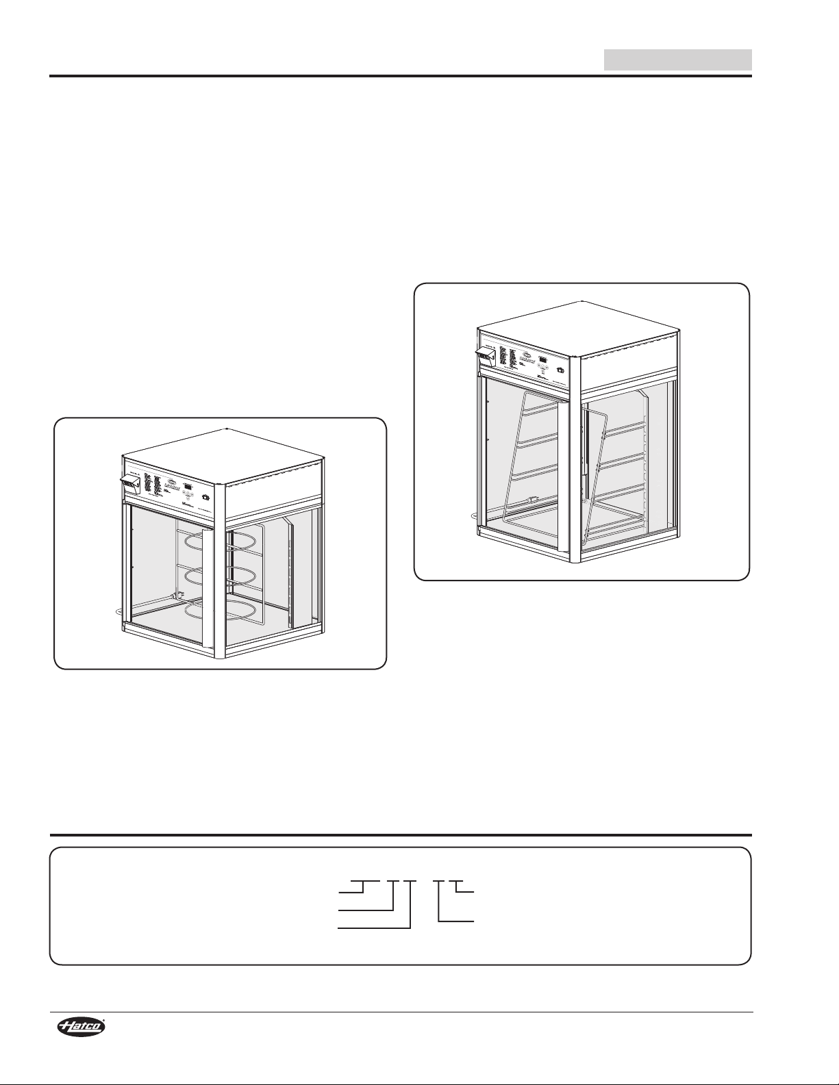
F S D T - x X
Flav-R-Savor
1 = One Door
2 = Two Doors
No Character = w/ Rack Motor
X = No Rack Motor
Display Cabinet
T = Tall
No Character = Standard Height
MODEL DESCRIPTION
English
All Models
Flav-R-Savor® Humidified Holding and Display Cabinets come
in either brushed aluminum or painted Designer colors. All units
feature a digital temperature controller, air heating system,
LED lights, tempered glass side panels, and a tempered glass
door(s). Units can be configured with or without a humidity
system with low water control protection. The standard access
door can be hinged left or right. The cabinet interior top and
bottom is made of easy-to-clean stainless steel. All available
display racks are nickel-plated except the pretzel tree display
rack, which is stainless steel. There are revolving and stationary
rack options that hold three to seven display trays.
FSD-1 and FSDT-1 Models
The FSD-1 is a standard single door model with a revolving
display motor. It has revolving and stationary rack options that
hold three to five display trays.
The FSDT-1 is a single door model with a revolving display
motor like the FSD-1, but is 5″ (127 mm) taller.
On each model, the rotating rack stops automatically when the
door is opened. For details on different rack options, refer to the
OPTIONS AND ACCESSORIES section.
FSD-2 and FSDT-2 Models
The FSD-2 and FSDT-2 are the same as models FSD-1 and
FSDT-1, but have an additional door on the opposite side of the
controls for pass-through convenience.
FSD-1X and FSDT-1X Models
The FSD-1X is a single door model with a stationary rack that
holds three display trays.
The FSDT-1X is a single door model with a stationary rack that
holds four display trays, but is 5″ (127 mm) taller.
For details on different rack options, refer to the OPTIONS
AND ACCESSORIES section.
FSD-1 Model
NOTE: Models FSD-1 and FSDT-1 cannot be converted to
models FSD-2/FSDT-2 or FSD-2X/FSDT-2X.
MODEL DESIGNATION
FSDT-1X Model
NOTE: Models FSD-1X and FSDT-1X cannot be converted to
models FSD-1/FSDT-1, FSD-2/FSDT-2, or FSD-2X/
FSDT-2X.
Models FSD-2X and FSDT-2X
The FSD-2X and FSDT-2X are the same as models
FSD-1X and FSDT-1X, but have an additional door on the
opposite side of the controls for pass-through convenience.
NOTE: Models FSD-2X and FSDT-2X cannot be converted to
models FSD-2/FSDT-2.
4
Form No. FSDM-0119
Page 5
English
WARNING
NEMA 5-15P
A B
C
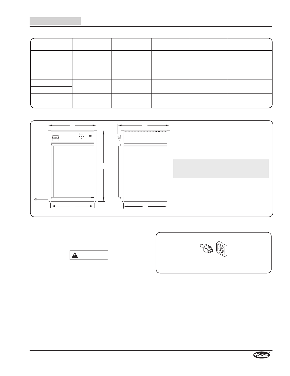
Front View SideView
D
E
Dimensions
SPECIFICATIONS
Width
Model
FSD-1
FSD-1X
FSD-2
FSD-2X
FSDT-1
FSDT-1X
FSDT-2
FSDT-2X
* Add 4″ (102 mm) to the height of the unit if the 4″ leg option is installed.
(A)
22-1/2″
(569 mm)
22-1/2″
(569 mm)
22-1/2″
(569 mm)
22-1/2″
(569 mm)
Depth
(B)
24-1/8″
(612 mm)
25-3/8″
(644 mm)
24-1/8″
(612 mm)
25-3/8″
(644 mm)
27-9/16″
(699 mm)
27-9/16″
(699 mm)
32-9/16″
(826 mm)
32-9/16″
(826 mm)
Height
(C)*
Cabinet Openings:
FSD Models: 19″W x 18-5/8″H (483 x 473 mm)
FSDT Models: 19″W x 23-3/4″H (483 x 603 mm)
Footprint
Width (D)
19-15/16″
(506 mm)
19-15/16″
(506 mm)
19-15/16″
(506 mm)
19-15/16″
(506 mm)
Footprint
Depth (E)
(508 mm)
(508 mm)
(508 mm)
(508 mm)
20″
20″
20″
20″
Plug Configurations
Units are supplied from the factory with an electrical cord and
plug installed. Plugs are supplied according to the applications.
ELECTRIC SHOCK HAZARD: Plug unit into a properly
grounded electrical receptacle of the correct voltage,
size, and plug configuration. If plug and receptacle do not
match, contact a qualified electrician to determine and
install proper voltage and size electrical receptacle.
NOTE: The specification label is located on the ceiling sheet
Form No. FSDM-0119
inside the unit. See label for serial number and
verification of unit electrical information.
Plug Configurations
NOTE: Receptacle not supplied by Hatco.
5
Page 6
SPECIFICATIONS
English
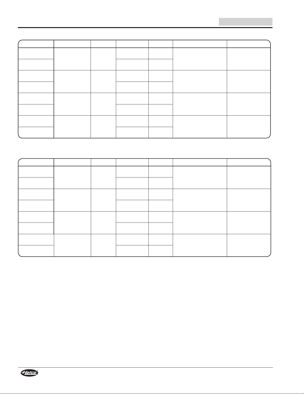
Electrical Rating Chart — FSD Models
Model Voltage Hertz Watts Amps Plug Conguration Shipping Weight
FSD-1
(with humidity)
FSD-1
(no humidity)
FSD-1X
(with humidity)
FSD-1X
(no humidity)
FSD-2
(with humidity)
FSD-2
(no humidity)
FSD-2X
(with humidity)
FSD-2X
(no humidity)
120 60
120 60
120 60
120 60
1414 11.8
NEMA 5-15P 113 lbs. (51 kg)
1089 9.1
1414 11.8
NEMA 5-15P 111 lbs. (50 kg)
1089 9.1
1414 11.8
NEMA 5-15P 114 lbs. (52 kg)
1089 9.1
1414 11.8
NEMA 5-15P 112 lbs. (51 kg)
1089 9.1
Electrical Rating Chart — FSDT Models
Model Voltage Hertz Watts Amps Plug Conguration Shipping Weight
FSDT-1
(with humidity)
FSDT-1
(no humidity)
FSDT-1X
(with humidity)
FSDT-1X
(no humidity)
FSDT-2
(with humidity)
FSDT-2
(no humidity)
FSDT-2X
(with humidity)
FSDT-2X
(no humidity)
120 60
120 60
120 60
120 60
1414 11.8
NEMA 5-15P 120 lbs. (54 kg)
1089 9.1
1414 11.8
NEMA 5-15P 118 lbs. (51 kg)
1089 9.1
1414 11.8
NEMA 5-15P 122 lbs. (55 kg)
1089 9.1
1414 11.8
NEMA 5-15P 120 lbs. (54 kg)
1089 9.1
NOTE: Shipping weight includes packaging.
6
Form No. FSDM-0119
Page 7
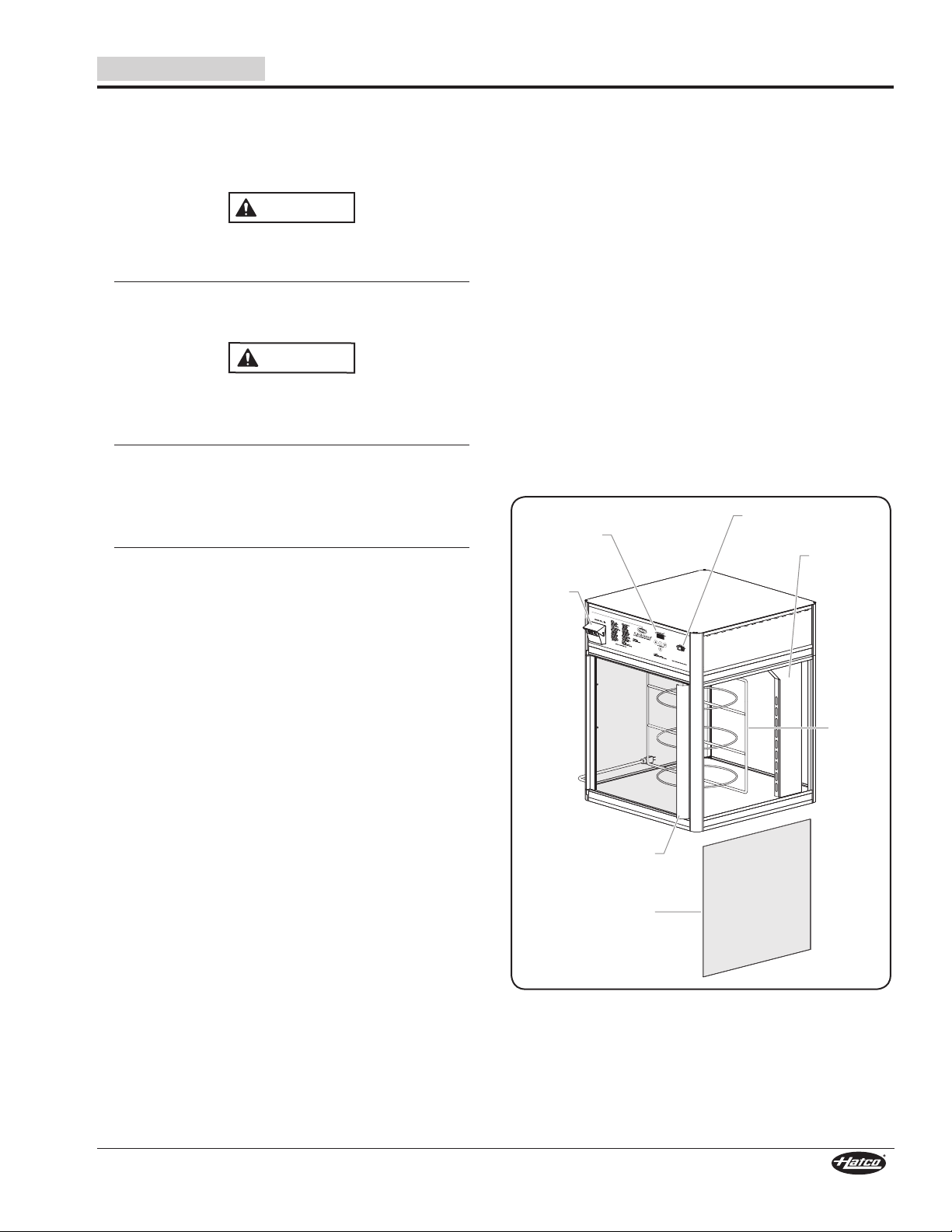
English
Fill Cup
Access Door
Glass Side
Panel
Digital
Temperature
Controller
POWER ON/OFF
(I/O) switch
Display
Rack
Air Heating
System
CAUTION
INSTALLATION
General
Flav-R-Savor® Humidified Holding and Display Cabinets
are shipped with most components installed and ready for
operation. The following installation instructions must be
performed before plugging in and operating the cabinet.
WARNING
ELECTRIC SHOCK HAZARD: Unit is not weatherproof.
Locate unit indoors where the ambient air temperature is
a minimum of 70°F (21°C).
FIRE HAZARD: Locate unit a minimum of 1″ (25 mm) from
combustible walls and materials. If safe distances are not
maintained, discoloration or combustion could occur.
Locate unit at the proper counter height in an area that is
convenient for use. The location should be level to prevent
the unit or its contents from falling accidentally and strong
enough to support the weight of the unit and contents.
The National Sanitation Foundation (NSF) requires that
units over 36″ (914 mm) in width or weighing more than
80 lbs. (36 kg) either be sealed to or raised above the
installation surface. If unit cannot be sealed at the point
of use, 4″ (102 mm) legs are available to allow for proper
cleaning access below unit.
Transport unit in upright position only. Before moving or
tipping unit, secure all glass surfaces with tape and drain
water from water reservoir. Failure to do so may result in
damage to unit or personal injury.
1. Remove the unit from the carton.
NOTE: To prevent delay in obtaining warranty coverage,
complete online warranty registration. See the
IMPORTANT OWNER INFORMATION section for
details.
2. Remove tape and protective packaging from all surfaces
of the unit, shelves, and any accessories.
• Floor Sheet — The stainless steel floor in all cabinets
is protected during shipping with a sheet of corrugated
cardboard. This protection must be removed prior to
cabinet operation.
• Display Rack — The display rack has packing material
and cardboard attached for protection during shipping.
This protection must be removed prior to cabinet
operation.
• Legs — The cabinets are shipped with four rubber
feet attached to the bottom of the unit. For cabinets
with the optional 4″ (102 mm) adjustable legs, see the
OPTIONS AND ACCESSORIES section for installation
instructions.
NOTE:If installing 4″ (102 mm) legs, do not remove glass
protection until leg installation is complete.
• Glass Side Panels — The cabinets have tempered glass
side panels that are protected during shipping using
foam sheets along the glass edges and tape to hold the
panels securely. The sheets and tape must be removed
prior to cabinet operation.
NOTE: Any impact to the tempered glass can cause breakage.
To remove a glass panel, grasp the panel firmly from
inside and outside of the cabinet. Lift up and out of the
bottom channel, then carefully lower the glass panel
until it clears the upper channel.
To reinstall, position the glass panel top edge under the
cabinet lip. Raise the panel until it clears the bottom
channel, then carefully lower the panel until it rests in
the bottom channel.
3. Place the unit in the desired location. Two people are
required for this step.
• Locate the unit in an area where the ambient air
temperature is constant and a minimum of 70°F
(21°C). Avoid areas that may be subject to active air
movements or currents (i.e., near exhaust fans/hoods,
air conditioning ducts, and exterior doors).
• Make sure the unit is at the proper counter height in an
area convenient for use.
• Make sure the countertop is level and strong enough to
support the weight of the unit and food product.
• Make sure all the feet on the bottom of the unit are
positioned securely on the countertop.
Components
Form No. FSDM-0119
7
Page 8
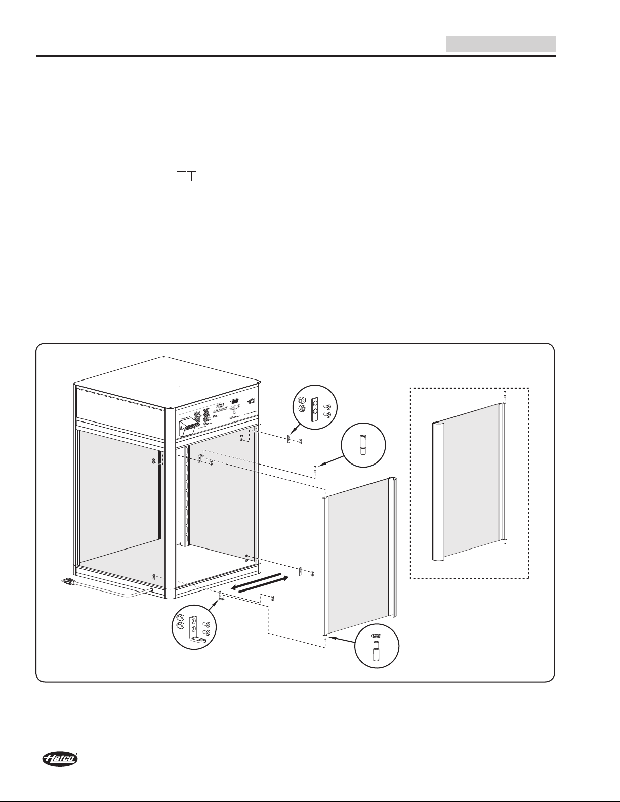
Hinge Assembly
Bottom Hinge Pin Screw and
Nylon Washer(s)
Door Rotated 180°
Top Hinge
Pin Screw
Striker Plate and
Hardware
INSTALLATION
1331
Year 2013
English
Reversing the Access Door
Flav-R-Savor Humidified Holding and Display Cabinet
access door(s) may be hinged on either the left or right side
for convenience. Use the following procedure to reverse the
access door.
NOTE: The last four digits in a ten digit numerical serial number
are the manufacturing date code.
Example:Serialnumber9625061331 has a date code
of “1331” which indicates:
Week Thirty-One
NOTE: For models with a date code of 1829 or older and
equipped with a motorized rotating rack (FSD-1,
FSD-2, FSDT-1, and FSDT-2), the “Relocating the
Proximity Switch” procedure in this section must be
performedafterreversingtheaccessdoor(s).
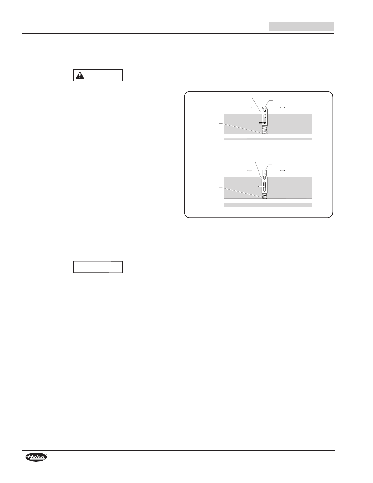
1. Remove the top hinge pin screw holding the door to the
hinge.
2. Tip the door assembly forward (away from cabinet) and
lift gently to clear the bottom hinge assembly. Remove the
nylon washer(s).
3. Reinstall the top hinge pin screw.
4. Remove the fluorescent lamp cover to allow access to the
hinge bracket/striker plate hardware, if necessary.
5. Remove the screws holding the hinges to the cabinet.
6. Remove the screws from the striker plates on the nonhinge side of the cabinet.
7. Install the striker plates on the opposite side of the cabinet
where the hinges were previously mounted.
8. Install the hinges on the opposite side of the cabinet
where the striker plates were previously mounted using
the original hinge mounting screws.
9. Replace the fluorescent lamp cover, if necessary.
10. Carefully rotate the door 180°.
11. Remove the hinge pin screw from the end that is now the
top.
12. Carefully place the door assembly with the nylon washer(s)
into the bottom hinge.
13. Tip/tilt the door assembly towards the cabinet and align the
door top with the hinge. Reinstall the top door hinge pin
screw through the hinge and into the door top.
Reversing the Access Door
8
Form No. FSDM-0119
Page 9
English
Proximity Switch
Orientation with Door
Opening from Left
(Hinged Right)
Proximity Switch
Orientation with Door
Opening from Right
(Hinged Left)
Screw
1331
Year 2013
INSTALLATION
Relocating the Proximity Switch
(Rotating Rack Models Only)
Date Code 1829 or older
NOTE: The last four digits in a ten digit numerical serial number
are the manufacturing date code.
Example:Serialnumber9625061331 has a date code
of “1331” which indicates:
Week Thirty-One
Units equipped with a rotating rack motor will require relocating
the proximity switch(es) after reversing the door(s).
The proximity switch signals the rack motor to stop when a door
is opened and to start when the door is closed. Follow the steps
below to move the proximity switch(es) to the proper position
after reversing the door(s). Unit requires one switch per door.
1. Turn off the unit, unplug the power cord, and allow the unit
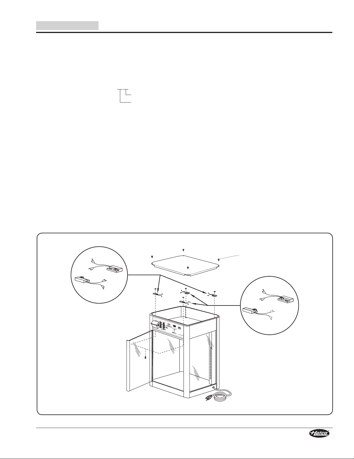
to cool.
2. Remove the four screws and top cover.
3. Remove the screw and nut securing the proximity switch
to the cabinet ceiling sheet. The screw is accessed from
inside the cabinet. Reinstall screw and nut into hole after
removing switch.
4. Cut the cable tie securing the proximity switch wires to
the wiring harness. Mark the two wires for reassembly
and unplug the wires from the proximity switch wire leads.
Route the wires to the opposite corner and reattach the
wires to the switch wire leads.
NOTE: Make sure to install the proximity switch in the
orientation shown below for the specific installation
location. Incorrect orientation will result in malfunction
of the proximity switch.
5. Remove the screw and nut from the new mounting hole.
Secure the proximity switch to the mounting hole with
the screw and nut. Make sure to maintain proper switch
orientation when tightening the hardware.
6. Make sure wires do not interfere with the other components
inside the cabinet, then secure switch wires to wiring
harness with a cable tie (not supplied).
NOTE: On models equipped with two doors, it may be
necessary to move the air chamber to access the
proximity switch on the customer-side door. Drain all
water from the unit, remove the drain plug from inside
the cabinet, and remove the four screws securing the
air chamber assembly to the cabinet. Carefully move
the air chamber out of the way to access the proximity
switch. Reassemble after relocating switch.
7. Install the top cover and four screws.
8. Plug the unit into the proper power source.
9. Turn on the unit and test the operation of the proximity
switch(es) by making sure the rack rotates when the doors
are closed and stops rotating when a door is opened.
Form No. FSDM-0119
Relocating the Proximity Switch
9
Page 10
WARNING
Fill Cup
WARNING
WARNING
OPERATION
English
General
Use the following procedures to operate the Flav-R-Savor®
Humidified Holding and Display Cabinets.
Read all safety messages in the IMPORTANT SAFETY
INFORMATION section before operating this equipment.
Startup
1. Plug unit into a properly grounded electrical receptacle of
the correct voltage, size and plug configuration. See the
SPECIFICATIONS section for details.
2. Move the Power I/O (on/off) switch to the I (on) position.
• The display lights will turn on and the heating system
will start up.
• The CABINET TEMPERATURE display will flash “LO
H2O” four times and then flash the cabinet temperature.
It will continue to alternate this way until the water
reservoir is filled. Once the reservoir is full, “LO H2O”
will stop flashing and the display will show the cabinet
temperature.
NOTICE
Use of distilled water in the water reservoir of humidified
units is recommended to preserve the life of electrical and
mechanical components. If non-distilled water is used, the
reservoir will require periodic cleaning and deliming (refer
to the MAINTENANCE section for cleaning procedure).
Unit failure due to lime or mineral deposits is not covered
under warranty.
Do not use deionized water. Deionized water will shorten
the life of the water reservoir and heating element.
NOTE: Unit failure caused by deionized water is not covered
by warranty.
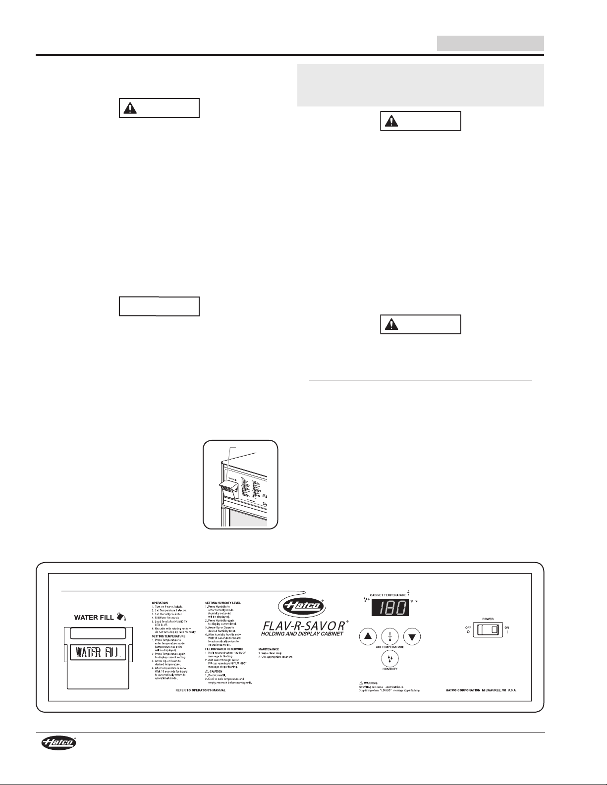
3. Fill the water reservoir with clean
water. To fill the reservoir:
a. Lift up the WATER FILL cup cover
and pull forward.
b. Slowly pour water into the cup until
“LO H2O” stops flashing on the
cabinet temperature display.
IMPORTANT NOTE
When using distilled water, add one teaspoon (5 g) of salt to
the water reservoir during the initial water fill only. This will
ensure proper operation of the water level sensors.
ELECTRIC SHOCK HAZARD: Do not overfill water reservoir.
Overfilling can cause electrical shock. Water reservoir is full
when “LO H2O” stops flashing on CABINET TEMPERATURE
display. Stop filling when “LO H2O” stops flashing on
display.
NOTE:Thecapacityofthewaterreservoiris3/4gallon(2.8l).
On the initial fill, the water reservoir may take up to one
gallon(3.8l)ofwater.
4. Set the humidity to the desired level (refer to the “Setting
the Humidity Level” procedure in this section). See the
“Food Holding Guide” for recommendations.
5. Set the air temperature to the desired temperature (refer to
the “Setting the Air Temperature” procedure in this section).
See the “Food Holding Guide” for recommendations.
6. Allow the unit 30 minutes to reach operating temperature
before loading the cabinet with pre-heated food product.
Make sure food product has been heated to the proper
food-safe temperature before placing in unit. Failure to
heat food product properly may result in serious health
risks. This unit is for holding pre-heated food product only.
BURN HAZARD: Some exterior surfaces on the unit will get
hot. Use caution when touching these areas.
FSD/FSDT Control Panel
10
Form No. FSDM-0119
Page 11
English
WARNING
Setting the Air Temperature
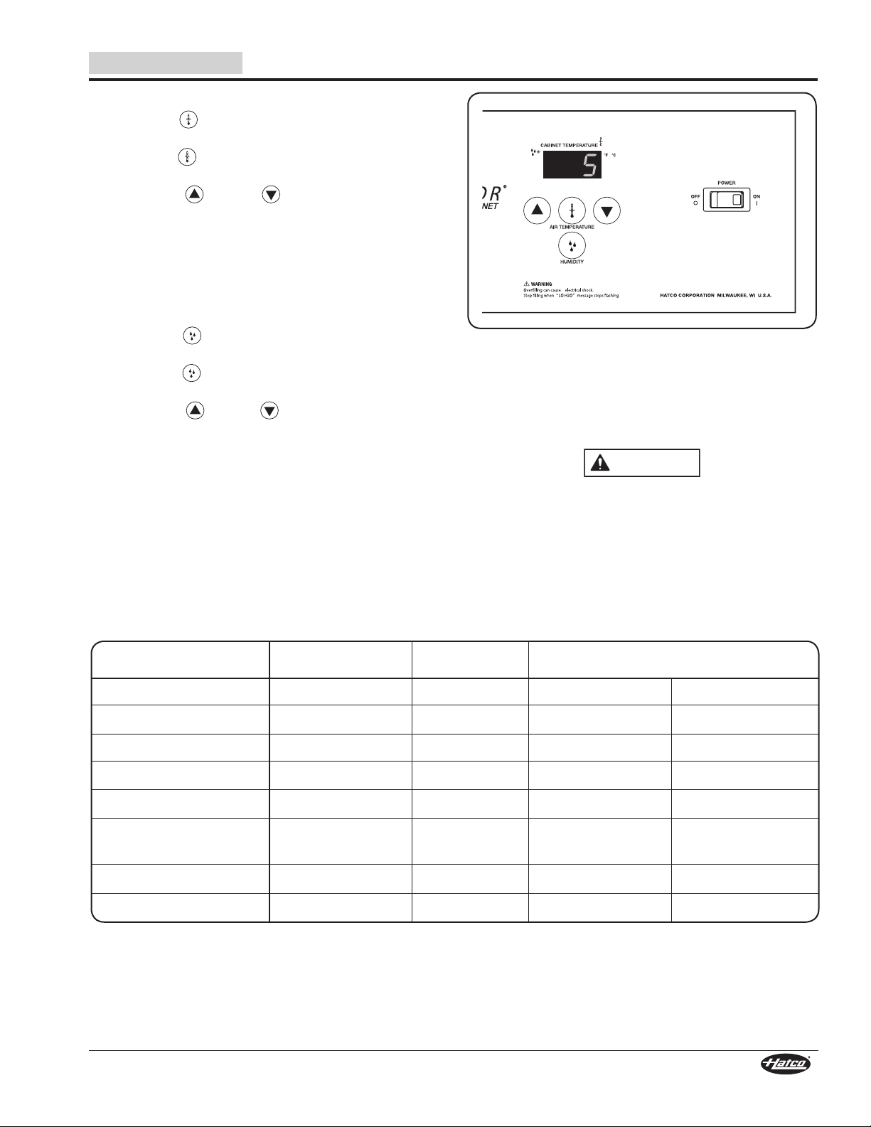
1. Press the key to enter temperature mode (“tSP” will
appear on the cabinet temperature display).
2. Press the key again to show the current temperature
setting.
3. Press the key or key to reach the desired
temperature. The temperature range is 80°–195°F
(27°–91°C) in single degree increments. See the “Food
Holding Guide” in this section for recommendations.
4. After the desired temperature is set, wait 15 seconds without
pushing any keys for the cabinet temperature display to
return automatically to operational mode.
Setting the Humidity Level
1. Press the key to enter humidity mode (“hSP” will
appear on the cabinet temperaturE display).
2. Press the key again to show the current humidity
level.
3. Press the key or key to reach the desired
humidity level. Humidity range is 1 through 5 (1 is the
lowest amount of humidity and 5 is the highest). See the
“Food Holding Guide” in this section for recommendations.
4. After the desired humidity level is set, wait 15 seconds
without pushing any keys for the cabinet temperature
display to return automatically to operational mode.
NOTE: Temperature and humidity settings may vary depending
upon product make-up and consistency. The CABINET
TEMPERATURE display shows the lowest temperature
point inside the cabinet, not the product temperature.
OPERATION
Setting the Humidity Level
The capacity of the water reservoir permits uninterrupted
operation for approximately 4–8 hours, depending on the
settings and how frequently the door is opened. When “LO
H2O” is flashing on the CABINET TEMPERATURE display,
add water to the reservoir. The water reservoir refill capacity is
approximately 96 ounces, or 3 quarts (2.8 liters).
ELECTRIC SHOCK HAZARD: Overfilling can cause
electrical shock. Water reservoir is full when “LO H2O”
stops flashing on CABINET TEMPERATURE display. Stop
filling when “LO H2O” stops flashing on display.
Food Holding Guide
Maximum Humidity Temperature
Type of Food Holding Time Setting °F °C
Biscuits 2 Hours 3 130–140 55–60
Chicken Pieces (Fried) 4 Hours 5 175 80
Croissants 4 Hours 1 140 60
Fruit Pies 3-1/2 Hours 4 140 60
Onion Rings 1/2 to 1 Hour 1 175 80
Pizza — Thick Crust 1 Hour 4 185 85
Thin Crust 1 Hour 5 180 82
Pretzels 3 Hours 4 140 60
Wrapped Sandwiches 2 Hours 4 180 82
NOTE: All times and settings are recommendations only and may vary depending on product preparation, cooking time, and
internal food temperature.
Form No. FSDM-0119
11
Page 12
Unlocked Position
Locked Position
Decompressed
Coupling
Motor Shaft
Rack
Shaft
Compressed
Coupling
Rack
Shaft
Motor Shaft
MAINTENANCE
English
General
The Flav-R-Savor® Humidified Holding and Display Cabinets
are designed for maximum durability and performance, with
minimum maintenance.
WARNING
ELECTRIC SHOCK HAZARD:
• Turn OFF power switch, unplug power cord, and
allow unit to cool before performing any cleaning,
adjustments, or maintenance.
• DO NOT submerge or saturate with water. Unit is not
waterproof. Do not operate if unit has been submerged
or saturated with water.
• Do not steam clean or use excessive water on unit.
• Use only Genuine Hatco Replacement Parts when
service is required. Failure to use Genuine Hatco
Replacement Parts may subject operators of the
equipment to hazardous electrical voltage, resulting in
electrical shock or burn. Genuine Hatco Replacement
Parts are specified to operate safely in the environments
in which they are used. Some aftermarket or generic
replacement parts do not have the characteristics that
will allow them to operate safely in Hatco equipment.
This unit has no “user-serviceable” parts. If service
is required on this unit, contact an Authorized Hatco
Service Agent or contact the Hatco Service Department at
800-558-0607 or 414-671-6350.
Removing the Rotating Rack
(Models FSD-1, FSDT-1, FSD-2, FSDT-2)
1. Open the front access door.
2. Pull down the spring-mounted coupling to compress.
3. Tip the rack until the rack shaft clears the motor shaft.
NOTE: Do not remove the bow cotter pin from the rack shaft.
Removing Motorized Display Racks
Daily Cleaning
To preserve the finish of the Flav-R-Savor Humidified Holding
and Display Cabinets, perform the following cleaning procedure
daily.
NOTICE
Use non-abrasive cleaners and cloths only. Abrasive
cleaners and cloths could scratch finish of unit, marring
its appearance and making it susceptible to soil
accumulation.
1. Turn off the unit, unplug the power cord, and allow the unit
to cool.
2. Remove and wash all food pans.
3. Wipe down all interior and exterior metal surfaces with a
damp cloth. Stubborn stains may be removed with a good
non-abrasive cleaner. Clean hard to reach areas using a
small brush and mild soap.
NOTE: Both the rotating display rack and the stationary rack
are removable for cleaning, if necessary. Refer to the
“Removing the Rotating Rack” procedure in this section
for removal.
4. Clean the glass side panels and door panel(s) using
ordinary glass cleaner and a damp, soft cloth or paper
towel. The side panels are removable for detailed cleaning,
if necessary. Refer to the “Removing the Glass Panels”
procedure in this section for removal.
Replacing the Rotating Rack
1. Insert the rack into the cabinet and place the rack bottom
point in the dimple located at the center of the cabinet floor.
2. Pull down the spring-mounted coupling to compress.
3. Tip the rack to line up the rack shaft with the motor shaft
pin.
4. Decompress the spring-mounted coupling until the
coupling is locked in place with the motor shaft pin.
Removing the Glass Panels
1. Lift the glass panel out of the bottom channel of the
cabinet.
2. Pull the lower edge away from the cabinet.
3. Carefully lower the glass until the top clears the cabinet.
Replacing the Glass Panel
1. Position the glass panel with the top edge under the top
cabinet lip, and raise the glass until it clears the bottom
channel of the cabinet.
2. Move the bottom of the glass towards the cabinet until the
glass rests against the cabinet frame.
3. Carefully lower the glass until it rests in the bottom channel
of the cabinet.
12
Form No. FSDM-0119
Page 13

English
CAUTION
Valve
Open
Valve
Closed
LED
Clip
LED
Housing
LED
Light
Strip
Wire
Connecto
r
MAINTENANCE
Draining the Water Reservoir
The water reservoir in humidified units must be drained prior to
moving the cabinet as well as during the “Removing Lime and
Mineral Deposits” procedure.
WARNING
ELECTRIC SHOCK HAZARD: Turn OFF power switch,
unplug power cord, and allow unit to cool before
performing any cleaning, adjustments, or maintenance.
1. Turn off the unit, unplug the power cord, and allow the unit
to cool.
2. Locate the valve inside the cabinet on the underside of the
ceiling sheet.
BURN HAZARD: Ceiling sheet and water in reservoir are
hot during operation. Allow to cool before draining.
3. Position a one gallon (four liter) container under the valve.
4. Turn the valve handle from the horizontal position (closed)
to the vertical position (open) to drain the reservoir.
5. Once the reservoir is empty, return the valve handle to the
closed position.
1. Turn off the unit, unplug the power cord, and allow the unit
to cool.
2. After the unit has cooled down, perform the “Draining the
Water Reservoir” procedure in this section.
3. Fill the water reservoir with a mixture of 75% water and
25% white vinegar. Do not use flavored vinegar.
4. Plug in and turn on the unit.
5. Set both the air temperature and humidity to their highest
settings and allow the unit to run for 30 minutes.
6. Turn off the unit, unplug the power cord, and allow the unit
to cool.
7. Perform the “Draining the Water Reservoir” procedure to
empty the deliming solution from the water reservoir.
8. Continue to fill and drain the water reservoir with clean
water until the deliming solution is rinsed through and the
water discharge is clean.
9. Plug the unit into its power source and fill the reservoir
as usual for daily operation using the procedure in the
OPERATION section of this manual.
Replacing an LED Light Strip
Units are equipped with two LED light strips that illuminate the
warming area. When replacing an LED light strip, use Hatco
P/N 04.29.405.90.
Use the following procedure to replace an LED light strip.
1. Turn off the unit, unplug the power cord, and allow the unit
to cool.
2. Pull the LED light strip from the clips securing it to the
corner.
3. Pull the top of the LED strip down and out of the LED
housing to expose the wire connectors.
4. Disconnect the wire connectors from the LED light strip
being replaced.
5. Connect the wire connectors from the new LED light strip.
6. Push the wiring and the top of the LED light strip up into
the LED housing.
7. Insert the LED light strip into the clips to secure it.
NOTE: If the water used has an excessive amount of lime or
NOTE: Unit failure caused by liming or sediment buildup is not
Removing Lime and Mineral Deposits
Use the following procedure for periodic cleaning and de-liming
of the water reservoir in humidified units.
NOTE: The lime and mineral content of the water used for
NOTE: Perform this procedure when the unit will not be used
Form No. FSDM-0119
Draining Reservoir Valve
mineral content, follow the REMOVING LIME AND
MINERAL DEPOSITS procedure for periodic cleaning
and deliming of the water reservoir.
covered under warranty.
daily operation will determine how often the deliming
procedure must be performed.
for a period of time, such as the end of the day.
Replacing an LED Light Strip (Door Removed for Clarity)
13
Page 14

MAINTENANCE
WARNING
WARNING
English
Setting the De-Liming Detection Mode
When de-liming detection mode is enabled, the controller will
indicate the presence of excessive lime build-up in humidified
models by showing “DE-L” on the CABINET TEMPERATURE
display. Use the following procedure to set de-liming detection
mode “on” or “off.”
1. Press and hold either the key or key for four seconds.
• When de-liming detection mode is enabled, the
CABINET TEMPERATURE display shows “L-ON” for
three seconds.
• When de-liming detection mode is disabled, the
CABINET TEMPERATURE display shows “L-OF” for
three seconds.
TROUBLESHOOTING GUIDE
This unit must be serviced by trained and qualified
personnel only. Service by unqualified personnel may lead
to electric shock or burn.
Symptom Probable Cause Corrective Action
LED lights not working. Loose wire connection. Verify wire connection is secure.
LED driver defective. Contact Authorized Service Agent or Hatco for assistance.
LED light strip defective. Replace the LED light strip. Refer to the “Replacing an LED
Unit operates, but is not
circulating air inside cabinet.
Unit is plugged in, but nothing
works
Unit is operational, but rotating
rack (if equipped) does not
turn.
Unit is not producing any “hot
air” inside cabinet.
Unit is heating, but is producing
too much humidity inside the
cabinet causing steam inside
unit.
Unit is heating, but is not
producing humidity inside
cabinet. “LO H20” not flashing on
display and unit is full of water.
Unit is heating, but is not
producing humidity inside
cabinet. “LO H20” flashes on
display and unit is full of water.
Blower motor is defective.
The correct voltage may not be supplied to blower.
No power to unit. Check electrical receptacle and verify that power supply
Power cord connections are loose or disconnected.
Defective POWER ON/OFF (I/O) switch.
Proximity switch was not relocated after door
reversal.
Proximity magnet or proximity switch not
working properly.
Incorrect voltage is supplied to rack motor.
Safety high-limit is tripped or open.
Incorrect voltage supplied to heating element.
Blower motor is not working.
Air heating element is defective.
Humidity control is set too high. Adjust the humidity control to a lower setting.
Air temperature is set too low. Adjust the temperature to a higher setting.
Humidity control is defective. Contact an Authorized Hatco Service Agent or Hatco for assistance.
Incorrect voltage supplied to water heating
element or heating element is defective.
When using distilled water, no minerals are being
sensed by low water probe.
Low water protection system is malfunctioning. Contact an Authorized Hatco Service Agent or Hatco for assistance.
ELECTRIC SHOCK HAZARD: Turn OFF power switch,
unplug power cord, and allow unit to cool before
performing any cleaning, adjustments, or maintenance.
Light Strip” in the MAINTENANCE section.
Contact an Authorized Hatco Service Agent or Hatco for assistance.
matches specifications on unit. If receptacle is not working,
check circuit breaker and reset, or plug unit into a different
known working receptacle.
Contact an Authorized Hatco Service Agent or Hatco for assistance.Power cord is damaged.
See “Relocating the Proximity Switch” in the INSTALLATION
section of this manual.
Contact an Authorized Hatco Service Agent or Hatco for assistance.
Contact an Authorized Hatco Service Agent or Hatco for assistance.
Contact an Authorized Hatco Service Agent or Hatco for assistance.
On initial fill, add one teaspoon of salt to the water reservoir.
14
Form No. FSDM-0119
Page 15

English
3-Tier Circle Rack*
Rack Openings: 4-5/8″ (117 mm)
5-Shelf Multi-Purpose Rack
Shelf 1 Rack Opening: 2-1/2″ (63 mm)
NOTE: Shelf 1 is the bottom shelf.
Shelves 2, 3, & 4 Rack Opening: 2-3/4″ (69 mm)
Shelves 2, 3, & 4 are removable.
3-Tier Pan Rack
Rack Openings: 3-1/2″ (89 mm)
*Racks designed for use
with motorized display.
4-Tier Circle Rack*
Rack Openings:
4-5/8″ (117 mm)
3-Tier Pretzel Tree*
Rack Openings:
5-7/8″ (149 mm)
7-Shelf Multi-Purpose Rack
Shelves 1 & 5 Rack Opening:
2-1/2″ (63 mm).
NOTE: Shelf 1 is the bottom shelf.
Shelves 2, 3, 4 & 6 Rack Openings:
2-3/4″ (69 mm)
Shelves 2, 3, 4, 6, & 7 are removable.
4-Tier Pan Rack
Rack Openings:
3-1/2″ (89 mm)
3-Shelf Angle Rack
Rack Openings: 3-1/2″ (89 mm)
Middle shelf is removable.
Rack shelves slant
at 15° angle.
*Racks designed
for use with
motorized display.
5-Tier Circle Rack*
Rack Openings:
3-7/8″ (98 mm)
TROUBLESHOOTING GUIDE
Error Codes
The following error codes may appear on the digital display to
indicate an error in the operating condition of the unit.
LO H20 = Low water probe does not detect water. Refill water
reservoir — refer to instructions in OPERATION
section of this manual.
E1 = Air temperature sensor malfunctioning. Contact an
Authorized Hatco Service Agent or Hatco for assistance.
E2 = Humidity temperature sensor malfunctioning. Contact an
Authorized Hatco Service Agent or Hatco for assistance.
dE-L = Water reservoir needs de-liming. Refer to the
“Removing Lime and Mineral Deposits” procedure
in the MAINTENANCE section of this manual to
clean and de-lime the water reservoir. Refer to the
“Setting the De-liming Detection Mode” procedure in
the MAINTENANCE section of this manual to set the
de-liming detection mode “on” or “off.” Contact
Authorized Service Agent or Hatco for assistance.
Troubleshooting Questions?
If you continue to have problems resolving an issue, please
contact the nearest Authorized Hatco Service Agency or Hatco
for assistance. To locate the nearest Service Agency, log onto
the Hatco website at www.hatcocorp.com, select the Support
pull-down menu, and click on “Find A Service Agent”; or contact
the Hatco Parts and Service Team at:
Telephone: 800-558-0607 or 414-671-6350
e-mail: support@hatcocorp.com
OPTIONS AND ACCESSORIES
Display Racks for FSD
Several display racks are available to “customize” FSD models to specific foodservice operations.
Display Racks for FSDT
Several display racks are available to “customize” FSDT models to specific foodservice operations.
Form No. FSDM-0119
15
Page 16

Corner Bracket
Rubber
Foot
4″ Leg
Lengthen
Shorten
Adjustable Tip
Decal
FSD-
INSET1
FSD-
INSET2
FSDT-
INSET1
FSDT-
INSET2
FSD-2CB
FSD-1CB
FSD-SQB
FSD-CTLH FSD-CUSH
NOTE: Make sure to specify color when ordering.
OPTIONS AND ACCESSORIES
English
4″ (102 mm) Adjustable Legs
The 4″ (102 mm) adjustable legs are used to add additional
height to the unit.
1. Secure all glass sides and doors with tape. Lay the unit on
its side. NOTICE: Do not lay unit on side with control
panel.
2. Remove the four screw-type rubber feet from the corner
brackets.
Installation of 4″ (102 mm) Legs
3. Screw the 4″ (102 mm) legs into
the holes in the middle of each
corner bracket. After all the legs
are tightened, return the unit to
its upright position. If the unit
is not level or rocks, turn the
adjustable tip of the appropriate
leg to level the unit.
Decorative Kits
Several decorative kits are available for all FSD models.
Installation instructions included with kits.
Top Cover Kits
Will hold a magnetic sign up to 23″ (584 mm) x 5-7/8″ (149 mm).
FSD-CTLH ...........Curved Hinge Header, Control Side
FSD-CUSH ..........Curved Header, Non-Control Side
Side Inset Kits
FSD-INSET1/FSDT-INSET1 ... Two Crescent Inset Panels
FSD-INSET2/FSDT-INSET2 ... Two Wave Inset Panels
Base Skirt Kits (requires 4″ [102 mm] legs, not
included)
Will hold a magnetic sign up to 20″ (508 mm) x 3-1/2″ (89 mm).
FSD-SQB ........... Flat Front, Back, and Side Panels
FSD-1CB ............ Curved Front Panel, Flat Back Panel, and
Flat Side Panels.
FSD-2CB ............ Curved Front and Back Panels, Flat Side Panels
Merchandising Decal
Self-adhesive merchandising decals are available to promote
food products. The decals are designed to be installed on three
(3) sides of the cabinet above the glass panels.
Decal Installation
1. Before installing decals, clean the side panels with a nonoily cleaner, such as isopropyl alcohol (rubbing alcohol).
2. After the cleaned surfaces have dried, remove the
protective backing from the decal and apply to the panel.
3. Any air pockets or bubbles behind the sticker can be
removed by rubbing gently with a soft cloth from the
center towards the outer edges.
Decal Installation
Decorative Kits
Motorless Rack Coupling
The motorless rack coupling allows the stationary installation of
a circle rack or pretzel tree in cabinets that do not have a rack
motor (FSD-1X, FSDT-1X,FSD-2X, FSDT-2X).
LED Lights
LED lights are available as accessories and come in two color
output options: Warm White (standard) and Neutral White.
16
Form No. FSDM-0119
Page 17

English
7-1/2″ (191 mm)
Sign Holder
3-1/4″ (83 mm)
Sign Holder
Screw
Water Reservoir
Fill Cup
LOW WATER
Indicator
TEMPERATURE
Control
CABINET
TEMPERATURE
Display
POWER ON/OFF
(I/O) Switch
HUMIDITY CYCLE Indicator
HUMIDITY
Control
Merchandising Display Sign Holders
Merchandising Display Sign Holders are available in heights of
3-1/4″ (83 mm) and 7-1/2″ (191 mm). The sign holders include a
metal holder and an acrylic window. Up to three sign holders can
be installed on a unit, one per side (excluding the control side).
1. Remove the existing screws securing the top cover in
place, position the sign holder over the screw holes, and
reinstall the screws.
2. Place the printed sign in the holder and slide the protective
acrylic window over the sign.
OPTIONS AND ACCESSORIES
Mechanical Thermostat Control Panel
The Mechanical Thermostat Control Panel is an alternative
to the digital control panel and features separate dials for
controlling temperature and humidity. This is a factory-installed
option and is not available for retrofit.
Merchandising Display Sign Holder
(3-1/2″ [83 mm] height shown)
Mechanical Thermostat Control Panel
Form No. FSDM-0119
17
Page 18

LIMITED WARRANTY
English
1. PRODUCT WARRANTY
Hatco warrants the products that it manufactures (the
“Products”) to be free from defects in materials and
workmanship, under normal use and service, for a period of
one (1) year from the date of purchase when installed and
maintained in accordance with Hatco’s written instructions
or 18 months from the date of shipment from Hatco. Buyer
must establish the Product’s purchase date by registering the
Product with Hatco or by other means satisfactory to Hatco in
its sole discretion.
Hatco warrants the following Product components to be free
from defects in materials and workmanship from the date of
purchase (subject to the foregoing conditions) for the period(s)
of time and on the conditions listed below:
a) One (1) Year Parts and Labor PLUS One (1) Additional
Year Parts-Only Warranty:
Conveyor Toaster Elements (metal sheathed)
Drawer Warmer Elements (metal sheathed)
Drawer Warmer Drawer Rollers and Slides
Strip Heater Elements (metal sheathed)
Display Warmer Elements (metal sheathed air heating)
Holding Cabinet Elements (metal sheathed air heating)
Heated Well Elements — HW and HWB Series
(metal sheathed)
b) Two (2) Year Parts and Labor Warranty:
Induction Ranges
Induction Warmers
c) One (1) Year Parts and Labor PLUS Four (4) Years
Parts-Only Warranty:
3CS and FR Tanks
d) One (1) Year Parts and Labor PLUS Nine (9) Years
Parts-Only Warranty on:
Electric Booster Heater Tanks
Gas Booster Heater Tanks
e) Ninety (90) Day Parts-Only Warranty:
Replacement Parts
THE FOREGOING WARRANTIES ARE EXCLUSIVE AND
IN LIEU OF ANY OTHER WARRANTY, EXPRESSED OR
IMPLIED, INCLUDING BUT NOT LIMITED TO ANY IMPLIED
WARRANTY OF MERCHANTABILITY OR FITNESS FOR
A PARTICULAR PURPOSE OR PATENT OR OTHER
INTELLECTUAL PROPERTY RIGHT INFRINGEMENT. Without
limiting the generality of the foregoing, SUCH WARRANTIES
DO NOT COVER: Coated incandescent light bulbs, fluorescent
lights, heat lamp bulbs, coated halogen light bulbs, halogen
heat lamp bulbs, xenon light bulbs, LED light tubes, glass
components, and fuses; Product failure in booster tank, fin
tube heat exchanger, or other water heating equipment caused
by liming, sediment buildup, chemical attack, or freezing;
or Product misuse, tampering or misapplication, improper
installation, or application of improper voltage.
2. LIMITATION OF REMEDIES AND DAMAGES
Hatco’s liability and Buyer’s exclusive remedy hereunder will
be limited solely, at Hatco’s option, to repair or replacement
using new or refurbished parts or Product by Hatco or a Hatcoauthorized service agency (other than where Buyer is located
outside of the United States, Canada, United Kingdom, or
Australia, in which case Hatco’s liability and Buyer’s exclusive
remedy hereunder will be limited solely to replacement of part
under warranty) with respect to any claim made within the
applicable warranty period referred to above. Hatco reserves
the right to accept or reject any such claim in whole or in part. In
the context of this Limited Warranty, “refurbished” means a part
or Product that has been returned to its original specifications
by Hatco or a Hatco-authorized service agency. Hatco will not
accept the return of any Product without prior written approval
from Hatco, and all such approved returns shall be made
at Buyer’s sole expense. HATCO WILL NOT BE LIABLE,
UNDER ANY CIRCUMSTANCES, FOR CONSEQUENTIAL
OR INCIDENTAL DAMAGES, INCLUDING BUT NOT LIMITED
TO LABOR COSTS OR LOST PROFITS RESULTING FROM
THE USE OF OR INABILITY TO USE THE PRODUCTS OR
FROM THE PRODUCTS BEING INCORPORATED IN OR
BECOMING A COMPONENT OF ANY OTHER PRODUCT OR
GOODS.
18
Form No. FSDM-0119
Page 19

Français
AVERTISSEMENT
Service d'assistance et de pièces de
le 800-558-0607.
SOMMAIRE
Informations Importantes pour le Propriétaire ................19
Introduction .........................................................................19
Consignes de Sécurité Importantes ................................. 20
Désignation du Modèle ...................................................... 21
Description du Modèle ....................................................... 22
Caractéristiques Techniques ............................................23
Dimensions ........................................................................ 23
Configuration des Fiches ................................................... 23
Tableau des valeurs nominales électriques ...................... 24
Installation ...........................................................................25
Généralités ........................................................................25
Inversion de la porte d’accès ............................................26
Déplacement du commutateur de proximité .....................27
Mode d’emploi ....................................................................28
Généralités ........................................................................28
Réglage de la température de l’air .................................... 29
Réglage du taux d’humidité ............................................... 29
Guide de maintien au chaud des aliments ........................ 29
INFORMATIONS IMPORTANTES POUR LE PROPRIÉTAIRE
Notez le numéro de modèle, le numéro de série, la tension
et la date d’achat de l’appareil dans les espaces ci-dessous
(L’étiquette des caractéristiques techniques se situe sur le
plafond à l’intérieur de l’appareil). Veuillez avoir cette information
à portée de la main si vous appelez Hatco pour assistance.
Modèle No. ______________________________________
Numéro de série __________________________________
Voltage _________________________________________
Date d’achat _____________________________________
Maintenance ........................................................................ 30
Généralités ........................................................................30
Nettoyage quotidien ...........................................................30
Retrait du présentoir rotatif ................................................ 30
Retrait des panneaux en verre .......................................... 30
Vidange du réservoir d’eau ...............................................31
Élimination des dépôts de tartre et de calcaire ................. 31
Remplacer une bande lumineuse DEL ..............................32
Réglage du mode de détection de détartrage ...................32
Guide de Dépannage ..........................................................33
Codes d’erreur ................................................................... 34
Options et accessoires ...................................................... 34
Garantie Limitée .................................................................37
Distributeurs de pièces autorisés ........Couverture Arrière
Horaires
ouvrables : 7h00 à 17h00 du lundi au vendredi
Heure du Centre (CT)
(Horaires d’été—juin à septembre:
7h00 à 17h00 du lundi au jeudi
7h00 à 16h00 le vendredi)
Téléphone: 800-558-0607; 414-671-6350
Courriel: support@hatcocorp.com
rechange disponible 7j/7, 24h/24 aux
États-Unis et au Canada en composant
Enregistrez votre appareil!
Remplissez la garantie en ligne pour éviter les retards
pour faire jouer la garantie. Accédez au site Web Hatco
www.hatcocorp.com, sélectionnez le menu déroulant
Support (Assistance), puis cliquez sur « Warranty » (Garantie).
Les armoires de présentation chauffées et humides
Flav-R-Savor® de Hatco sont conçues pour conserver des plats
préparés pendant des périodes relativement longues, tout en
maintenant leur fraîcheur intacte. Les armoires chauffées
et humides de Hatco offrent le meilleur environnement pour
conserver les produits alimentaires en réglant la température
de l’air et en équilibrant en même temps le niveau d’humidité.
L’utilisation d’une chaleur et d’une humidité contrôlées permet
de maintenir la texture et la température de service plus
longtemps que le matériel de conservation à sec traditionnel.
Le flux d’air circulant dans les appareils Flav-R-Savor est conçu
pour maintenir une température constante dans l’armoire tout
en évitant de dessécher les aliments. La combinaison de
niveaux précis de température et d’humidité crée un effet de “
couverture “ autour des aliments. L’intensité du flux d’air permet
à la température intérieure de l’armoire de se restabiliser
rapidement après l’ouverture et la fermeture de la porte.
Les armoires de présentation chauffées et humides Hatco sont
le fruit de recherches poussées et d’essais sur site complets.
Les matériaux utilisés ont été sélectionnés pour un maximum de
durabilité, d’aspect esthétique et de performance optimum. Chaque
appareil est minutieusement inspecté et testé avant expédition.
Formulaire n° FSDM-0119
Des renseignements supplémentaires sont disponibles sur
notre site Web à www.hatcocorp.com.
INTRODUCTION
Ce manuel fournit les instructions d’installation, les consignes
de sécurité et le mode d’emploi des armoires de présentation
chauffées et humides. Hatco vous recommande de lire l’ensemble
des instructions d’installation, de sécurité et de fonctionnement
contenues dans ce manuel avant d’installer et d’utiliser l’appareil.
Les consignes de sécurité qui apparaissent dans ce manuel
sont identifiées par les mots indicateurs suivants :
AVERTISSEMENT indique une situation dangereuse qui,
si elle n’est pas évitée, peut provoquer la mort ou des
blessures graves.
ATTENTION
ATTENTION indique une situation dangereuse qui, si elle
n’est pas évitée, peut provoquer des blessures légères ou
moyennes.
AVIS
AVIS est utilisé pour des questions sans rapport avec des
blessures corporelles.
19
Page 20

AVERTISSEMENT
ATTENTION
AVERTISSEMENT
CONSIGNES DE SÉCURITÉ IMPORTANTES
Lisez l’information de securite importante suivante avant d’utiliser cet équipement pour éviter
des dommages ou la mort sérieux et pour éviter d’endommager l’équipement ou la propriété.
Français
DANGER DE DÉCHARGE ÉLECTRIQUE :
• Brancher l’appareil sur une prise de courant avec terre
de tension, de format et de configuration des broches
corrects. Si la fiche et la prise ne se correspondent pas,
s’adresser à un électricien qualifié pour déterminer et
installer une prise de courant de format et de tension
corrects.
• Éteignez l’appareil et débranchez le cordon
d’alimentation de la prise secteur et laissez refroidir
avant une maintenance ou un nettoyage.
• NE PAS immerger l’appareil ni le saturer d’eau.
L’appareil n’est pas étanche à l’eau. Ne pas le faire
fonctionner s’il a été immergé ou saturé d’eau.
• L’appareil n’est pas à l’épreuve des intempéries. Placer
l’appareil à l’intérieur à une température ambiante de
21°C minimum.
• Cet appareil n’est pas étanche aux jets. Ne pas utiliser
de jet sous pression pour nettoyer l’appareil.
• Ne pas tirer l’appareil par son cordon électrique.
• Ne pas utiliser l’appareil si le cordon est endommagé
ou usé.
• Ne pas tenter de réparer ni de changer un cordon
électrique endommagé. Ce cordon doit être changé
par Hatco, par un réparateur Hatco agréé ou par une
personnes de qualifications comparables.
• Ne pas trop remplir le réservoir d’eau. Un remplissage
excessif peut causer une électrocution. La réservoir
d’eau est plein quand « LO H2O » cesse de clignoter
sur l’affichage CABINET TEMPERATURE (température
de l’armoire). Arrêter de remplir quand « LO H2O »
cesse de clignoter sur l’affichage.
• Couper l’alimentation et laisser l’appareil refroidir
avant de vider l’eau du réservoir.
• Cet appareil doit uniquement être réparé par un
personnel qualifié. Toute réparation par un personnel
non qualifié peut entraîner une électrocution et des
brûlures.
• Utilisez uniquement des pièces de rechange d’origine
Hatco lorsque l’entretien est nécessaire. Utilisez des
pièces détachées Hatco authentiques sous peine
d’annuler toutes les garanties et d’exposer l’utilisateur
à des tensions électriques dangereuses pouvant
entraîner une électrocution ou des brûlures. Les pièces
de rechange authentiques Hatco sont spécifiées pour
fonctionner en toute sécurité dans les environnements
dans lesquels elles sont utilisées. Certaines pièces de
rechange génériques ou d’après-vente n’ont pas les
caractéristiques qui leur permettent d’opérer en toute
sécurité dans les équipements Hatco.
DANGER D’INCENDIE : Placer l’appareil à un minimum
de 25 mm des parois et matières combustibles. Si une
distance sûre n’est pas maintenue, la chaleur peut
provoquer une combustion ou une altération de couleur.
Cet appareil ne contient aucune pièce réparable par
l’utilisateur. Si cet appareil doit être réparé, contacter un
réparateur Hatco agréé ou le Service après-vente Hatco au
+1 414-671-6350.
Cet appareil ne doit pas être utilisé par des enfants ou des
personnes avec des capacités physiques, sensorielles ou
mentales diminuées. Assurez-vous que les enfants sont
bien surveillés et tenez-les à l’écart de l’appareil.
Assurez-vous que tous les opérateurs ont été formés à
l’utilisation sûre et correcte de l’appareil.
S’assurer que le produit alimentaire a été chauffé à une
température adaptée au maintien de sa salubrité avant de
le mettre dans l’appareil sous peine de risques graves pour
la santé. Cet appareil est destiné au maintien au chaud de
produits alimentaires préchauffés uniquement.
Hatco n’est pas responsable de la température de service
du produit alimentaire elle-même. Il incombe à l’utilisateur
de s’assurer que le produit alimentaire est maintenu et
servi à une température sûre.
DANGER DE BRÛLURE : Certaines surfaces extérieures
de l’appareil deviennent chaudes. Toucher ces zones de
l’appareil avec précaution.
Placer l’appareil sur un plan de travail de hauteur correcte
à un endroit qui convient pour son utilisation. Le support
doit être de niveau pour éviter toute chute accidentelle du
grille-pain ou de son contenu et suffisamment solide pour
résister au poids de l’appareil et de son contenu.
La National Sanitation Foundation (NSF) exige que les
appareils mesurant plus de 914 mm (36″) de largeur et
pesant plus de 36 kg (80 lbs.) soient hermétiquement
fixés ou rehaussés sur la surface d’installation. Si vous
ne pouvez pas fixer l’appareil à son endroit d’utilisation,
montez-le sur les pieds de 102 mm (4″) pour pouvoir
facilement nettoyer en dessous.
Transporter l’appareil à la verticale seulement. Avant de
déplacer ou basculer l’appareil, fixer toutes les surfaces
en verre avec du ruban adhésif et vider l’eau du réservoir
sous peine d’endommagement de l’appareil ou de
blessures personnelles.
20
Formulaire n° FSDM-0119
Page 21

Français
AVIS
AVIS
F S D T - x X
Flav-R-Savor
1 = Une porte
2 = Deux portes
Pas de lettre = Présentoir avec moteur
X = Présentoir sans moteur
Armoire de présentation
T = Tall (grande)
Pas de lettre = Hauteur standard
CONSIGNES DE SÉCURITÉ IMPORTANTES
L’emploi d’eau distillée dans le réservoir d’eau des
modèles humides est recommandé pour préserver la
durée de vie des composants électriques et mécaniques.
Si de l’eau non distillée est utilisée, le réservoir exigera un
nettoyage et un détartrage périodiques (pour la procédure
de nettoyage, voir la section Maintenance). Les pannes
d’appareil faute d’avoir enlevé le tartre ou les dépôts
calcaires ne sont pas couvertes par la garantie.
Ne pas utiliser l’eau désionisée. L’eau désionisée
raccourcira la durée de vie du réservoir d’eau et l’élément
chauffant.
Nettoyer chaque jour l’appareil pour éviter les
dysfonctionnements et maintenir l’hygiène.
N’installez pas l’appareil dans un endroit présentant des
déplacements d’air excessifs. Évitez les zones pouvant
être soumises à des déplacements d’air ou à des courants
d’air actifs (proximité de ventilateurs d’extraction/de
hottes d’aspiration, de conduites de climatisation et de
portes extérieures).
Utiliser uniquement des produits nettoyants non abrasifs.
Les produits nettoyants abrasifs peuvent rayer la finition
de l’appareil, ce qui altère son apparence et le rend plus
susceptible d’accumuler la saleté.
DÉSIGNATION DU MODÈLE
Formulaire n° FSDM-0119
21
Page 22

DESCRIPTION DU MODÈLE
Français
Tous les Modèles
Les armoires de présentation chauffées et humides
Flav-R-Savor® sont proposées en aluminium brossé ou en
couleurs Designer peintes. Tous les appareils ont un régulateur
thermique numérique, un système de chauffage de l’air,
Lumières DEL, et des panneaux latéraux et une porte en verre
trempé. Les appareils peuvent être configurés avec ou sans
système d’humidification avec contrôle de bas niveau d’eau.
La porte d’accès standard peut avoir ses charnières à gauche
ou à droite. Le haut et le bas de l’intérieur de l’armoire sont
en inox facile à nettoyer. Tous les présentoirs disponibles sont
nickelés, sauf l’arbre à bretzels, qui est en inox. Des options
de présentoirs fixes et stationnaires pouvant contenir de trois à
sept plateaux de présentation sont disponibles.
Modèles FSD-1 et FSDT-1 Models
Le FSD-1 est un modèle à une porte avec moteur de vitrine
rotative.
Le FSDT-1 est un modèle à une porte avec moteur de vitrine
rotative comme le FSD-1, mais il mesure 127 mm (5″) de plus
en hauteur. Il est proposé avec des options de présentoirs
fixes et rotatifs pouvant contenir de trois à sept plateaux de
présentation.
Sur chaque modèle, le présentoir rotatif s’arrête
automatiquement à l’ouverture de la porte. Pour des détails
sur les différentes options de grille, voir la section OPTIONS
ET ACCESSOIRES.
Modèles FSD-2 et FSDT-2 Models
Le FSD-2 et le FSDT-2 sont identiques aux modèles FSD-1
et FSDT-1, à ceci près qu’ils ont une porte supplémentaire du
côté opposé des commandes pour faire passer plus facilement
les plats.
Modèles FSD-1X et FSDT-1X Models
Le FSD-1X est un modèle à porte unique avec un présentoir
fixe contenant trois plateaux de présentation.
Le FSDT-1X est un modèle à porte unique avec un présentoir
fixe contenant quatre plateaux de présentation, mais qui est
plus grand de 127 mm (5″).
Pour des détails sur les différentes options de grille, voir la
section OPTIONS ET ACCESSOIRES.
Modèle FSD-1
NOTA : Les modèles FSD-1 and FSDT-1 ne peuvent pas
être convertis en modèles FSD-2/FSDT-2 or FSD-2X/
FSDT-2X.
Modèle FSDT-1X
NOTA : Les modèles FSD-1X et FSDT-1X ne peuvent pas être
convertis en modèles FSD-1/FSDT-1, FSD-2/FSDT-2
ou FSD-2X/FSDT-2X.
Modèles FSD-2X et FSDT-2X
Le FSD-2X et le FSDT-2X sont identiques aux modèles FSD-1X
et FSDT-1X, à ceci près qu’ils ont une porte supplémentaire du
côté opposé des commandes pour faire passer plus facilement
les plats.
NOTA : Les modèles FSD-2X et FSDT-2X ne peuvent pas être
convertis en modèles FSD-2/FSDT-2.
22
Formulaire n° FSDM-0119
Page 23

Français
AVERTISSEMENT
NEMA 5-15P
A B
C
Vue de face Vue de côté
D
E
Dimensions
CARACTÉRISTIQUES TECHNIQUES
Largeur
Modèle
FSD-1
FSD-1X
FSD-2
FSD-2X
FSDT-1
FSDT-1X
FSDT-2
FSDT-2X
* Ajouter 102 mm (4″) à la hauteur (C) lorsque les jambes de 102 mm (4″) sont installées.
(A)
569 mm
(22-1/2″)
569 mm
(22-1/2″)
569 mm
(22-1/2″)
569 mm
(22-1/2″)
Profonduer
(B)
612 mm
24-1/8″)
644 mm
(25-3/8″)
612 mm
24-1/8″)
644 mm
(25-3/8″)
Hauteur
(C)*
699 mm
(27-9/16″)
699 mm
(27-9/16″)
826 mm
(32-9/16″)
826 mm
(32-9/16″)
Ouvertures d’armoire:
Modèle FSD: 483 x 473 mm (19″W x 18-5/8″H)
Modèle FSDT: 483 x 603 mm (19″W x 23-3/4″H)
d’encombrement
Largeur
(D)
506 mm
(19-15/16″)
506 mm
(19-15/16″)
506 mm
(19-15/16″)
506 mm
(19-15/16″)
Profonduer
d’encombrement
(E)
508 mm
(20″)
508 mm
(20″)
508 mm
(20″)
508 mm
(20″)
Configuration des fiches
Les appareils sortent de l’usine avec un cordon électrique et
une fiche installée. Les fiches sont fournies en fonction de
l’application.
DANGER DE DÉCHARGE ÉLECTRIQUE: Brancher
l’appareil sur une prise de courant avec terre de tension,
de format et de configuration des broches corrects. Si la
fiche et la prise ne se correspondent pas, s’adresser à un
électricien qualifié pour déterminer et installer une prise
de courant de format et de tension corrects.
NOTA: L’étiquette des caractéristiques techniques se situe sur
le plafond à l’intérieur de l’appareil.
Formulaire n° FSDM-0119
Configuration des fiches
NOTA: Prise non fournie par Hatco.
23
Page 24

CARACTÉRISTIQUES TECHNIQUES
Tableau des valeurs nominales électriques — Modèles FSD
Français
Conguration
Modèle Tension Puissance Intensité Amps
FSD-1
(avec humidité)
FSD-1
(sans humidité)
FSD-1X
(avec humidité)
FSD-1X
(sans humidité)
FSD-2
(avec humidité)
FSD-2
(sans humidité)
FSD-2X
(avec humidité)
FSD-2X
(sans humidité)
120 60
120 60
120 60
120 60
1414 11.8
1089 9.1
1414 11.8
1089 9.1
1414 11.8
1089 9.1
1414 11.8
1089 9.1
Tableau des valeurs nominales électriques — Modèles FSDT
Conguration
Modèle Tension Puissance Intensité Amps
FSDT-1
(avec humidité)
FSDT-1
(sans humidité)
FSDT-1X
(avec humidité)
FSDT-1X
(sans humidité)
FSDT-2
(avec humidité)
FSDT-2
(sans humidité)
FSDT-2X
(avec humidité)
FSDT-2X
(sans humidité)
120 60
120 60
120 60
120 60
1414 11.8
1089 9.1
1414 11.8
1089 9.1
1414 11.8
1089 9.1
1414 11.8
1089 9.1
Poids
de Fiches
NEMA 5-15P 51 kg (113 lbs.)
NEMA 5-15P 50 kg (111 lbs.)
NEMA 5-15P 52 kg (114 lbs.)
NEMA 5-15P 51 kg (112 lbs.)
d’embarquement
Poids
de Fiches
NEMA 5-15P 54 kg (120 lbs.)
NEMA 5-15P 51 kg (118 lbs.)
NEMA 5-15P 55 kg (122 lbs.)
NEMA 5-15P 54 kg (120 lbs.)
d’embarquement
NOTA: Le poids d’embarquement comprend l’emballage.
24
Formulaire n° FSDM-0119
Page 25

Français
Godet de
remplissage
Porte d'accès
Panneau latéral
en verre
Régulateur de
température
numérique
Interrupteur de
marche/arrêt (I/O)
Présentoir
Système de
chauffage de
l'air
AVERTISSEMENT
ATTENTION
INSTALLATION
Généralités
Les armoires de présentation chauffées et humides
Flav-R-Savor® sont expédiées avec la plupart des composants
installés et prêts à l’emploi. Les instructions d’installation
suivantes doivent être respectées avant de brancher et de faire
fonctionner l’armoire.
DANGER DE DÉCHARGE ÉLECTRIQUE: L’appareil n’est
pas à l’épreuve des intempéries. Placer l’appareil à
l’intérieur à une température ambiante de 21°C minimum.
DANGER D’INCENDIE : Placer l’appareil à un minimum
de 25 mm des parois et matières combustibles. Si une
distance sûre n’est pas maintenue, la chaleur peut
provoquer une combustion ou une altération de couleur.
Placer l’appareil sur un plan de travail de hauteur correcte
à un endroit qui convient pour son utilisation. Le support
doit être de niveau pour éviter toute chute accidentelle du
grille-pain ou de son contenu et suffisamment solide pour
résister au poids de l’appareil et de son contenu.
La National Sanitation Foundation (NSF) exige que les
appareils mesurant plus de 914 mm (36″) de largeur et
pesant plus de 36 kg (80 lbs.) soient hermétiquement
fixés ou rehaussés sur la surface d’installation. Si vous
ne pouvez pas fixer l’appareil à son endroit d’utilisation,
montez-le sur les pieds de 102 mm (4″) pour pouvoir
facilement nettoyer en dessous.
Transporter l’appareil à la verticale seulement. Avant de
déplacer ou basculer l’appareil, fixer toutes les surfaces
en verre avec du ruban adhésif et vider l’eau du réservoir
sous peine d’endommagement de l’appareil ou de
blessures personnelles.
1. Retirer l’appareil de sa boîte.
NOTA: Pour éviter des retards dans l’obtention de la couverture
de la garantie, complétez l’enregistrement en ligne
de votre garantie. Lisez la section INFORMATIONS
IMPORTANTES POUR LE PROPRIETAIRE pour plus
de détails.
2. Retirez le ruban et l’emballage de protection de toutes les
surfaces de l’appareil, des plaques et des accessoires.
• Plancher — Le plancher inox dans toutes les armoires
est protégé durant l’expédition par du carton ondulé.
Cette protection devra être enlevée avant la mise en
marche de l’appareil.
• Présentoir — Du matériel d’emballage et du carton sont
attachés en guise de protection durant l’expédition.
Cette protection devra être enlevée avant la mise en
marche de l’appareil.
• Pieds — Les armoires sont expédiées avec quatre
pieds en caoutchouc attachés en bas. Pour les armoires
avec pieds réglables de 102 mm (4″) en option, voir les
instructions d’installation à la section OPTIONS ET
ACCESSOIRES.
NOTA: Silespiedsde102mm(4″)sontinstallés,nepasenlever
la protection en verre avant la fin de l’installation.
• Panneaux latéraux en verre — Les armoires ont des
panneaux latéraux en verre trempé qui sont protégés
en cours d’expédition par des feuilles de polystyrène
placées le long des bords en verre et fixés en toute
sécurité par un ruban adhésif. Les feuilles de polystyrène
et le ruban adhésif devront être enlevés avant la mise
en marche de l’appareil.
NOTA: Tout impact sur le verre trempé peut le casser.
Pour enlever un panneau en verre, le saisir fermement
par l’intérieur et l’extérieur de l’armoire. Soulever et
sortir de la coulisse inférieure, puis abaisser le panneau
en verre avec précaution jusqu’à ce qu’il sorte de la
coulisse supérieure.
Pour réinstaller, positionner le bord supérieur du
panneau en verre sous le rebord de l’armoire. Soulever
le panneau jusqu’à ce qu’il sorte de la coulisse inférieure,
puis abaisser le panneau en verre avec précaution
jusqu’à ce qu’il repose dans la coulisse inférieure.
3. Placez l’appareil à l’endroit désiré.
• Placez l’appareil à un endroit où la température ambiante
est constante et de 21°C (70°F) minimum. Évitez les
endroits susceptibles d’activer les mouvements ou les
courants d’air (proximité des ventilateurs ou hottes
d’évacuation et conduites de climatisation).
• Assurez-vous que l’appareil est à la bonne hauteur du plan
de travail dans un espace pratique pour son utilisation.
• Assurez-vous que le plan de travail est de niveau et
suffisamment solide pour supporter le poids de l’appareil
et des produits alimentaires.
• Veillez à ce que tous les pieds sous l’appareil sont bien
positionnés sur le plan de travail.
Formulaire n° FSDM-0119
Composants
25
Page 26

Charnière
Vis d'axe de charnière
inférieure et rondelle nylon
Porte tournée de 180°
Vis d'axe de
charnière
supérieure
Gâche et visserie
INSTALLATION
Semaine trente et un
1331
Français
Inversion de la porte d’accès
La porte d’accès des armoires de présentation chauffées et
humides Flav-R-Savor® peut avoir les charnières à gauche ou
à droite pour plus de commodité. Procéder comme suit pour
inverser la porte d’accès.
NOTA: Les quatre derniers chiffres du numéro de série à
10 chiffres correspondent au code de la date de
fabrication.
Parexemple :Lenumérodesérie 9625061331aun
code de la date égal à« 1331 »qui signifie :
Année 2013
NOTA: Pour les modèles possédant un code de date égal
à 1829 ou antérieur et équipés d’un présentoir rotatif
motorisé (FSD-1, FSD-2, FSDT-1 et FSDT-2), la
procédure de « Déplacement du commutateur de
proximité » doit être réalisée après avoir inversé la/les
porte(s)d’accès.
1. Enlever la vis de l’axe de charnière supérieur qui fixe la
porte à la charnière.
2. Basculer la porte vers l’avant (loin de l’armoire) et la
soulever avec précaution pour la dégager de la charnière
inférieure. Enlever la rondelle nylon.
3. Réinstaller l’axe de charnière supérieur.
4. Retirer le couvercle de la lampe fluorescente pour
accéder au support de charnière/à la plaque de butée, si
nécessaire.
5. Enlever les vis qui fixent les charnières à l’armoire.
6. Enlever les vis des gâches du côté opposé des charnières.
7. Installer les gâches de l’autre côté, là où se trouvaient les
charnières.
8. Installer les charnières du côté de l’armoire où se trouvaient
les gâches en utilisant les vis d’origine.
9. Remettre le couvercle de la lampe fluorescente, si
nécessaire.
10. Tourner la porte avec précaution de 180°.
11. Enlever la vis de l’axe de charnière de l’extrémité qui est
désormais le haut.
12. Placer avec précaution la porte avec la rondelle nylon
dans la charnière du bas.
13. Basculer/incliner la porte vers l’armoire et aligner le haut
de la porte sur la charnière. Réinstaller la vis de l’axe de
charnière supérieure à travers la charnière et dans le haut
de la porte.
Inversion de la porte d’accès
26
Formulaire n° FSDM-0119
Page 27

Français
Fixation du commutateur de
proximité avec ouverture
de porte à partir de la droite
(charnières à gauche)
Fixation du commutateur de
proximité avec ouverture
de porte à partir de la gauche
(charnières à droite)
Vis
Semaine trente et un
1331
INSTALLATION
Deplacement du Commutateur de Proxmite
(Modèless de Présentoirs Rotatifs Uniquement FSD-1, FSDT-1, FSD-2, FSDT-2)
Code de la date égal à 1829 ou antérieur
NOTA: Les quatre derniers chiffres du numéro de série à
10 chiffres correspondent au code de la date de
fabrication.
Parexemple :Lenumérodesérie 9625061331aun
code de la date égal à« 1331 »qui signifie :
Année 2013
Sur les modèles FSD équipés d’un présentoir rotatif, vous
devez déplacer le(s) commutateur(s) de proximité lorsque vous
inversez la ou les portes.
Le commutateur de proximité arête la rotation du présentoir
lorsque la porte est ouverte. Procédez comme suit de sorte
que le commutateur de proximité se trouve dans la bonne
position après inversion de la ou des portes. L’appareil exige
un commutateur par porte.
1. Éteindre l’appareil, débrancher le cordon d’alimentation et
laisser refroidir l’appareil.
2. Retirez les quatre vis et le capot supérieur.
3. Retirez la vis et l’écrou qui fixent le commutateur de
proximité sur l’armoire. La vis est accessible par l’intérieur
de l’appareil. Réinstallez la vis et l’écrou dans le trou après
avoir retiré le commutateur.
4. Coupez l’attache de câble qui fixe les conducteurs du
commutateur de proximité au faisceau de câblage.
Marquez les deux conducteurs pour faciliter le remontage
et débranchez les conducteurs du commutateur de
proximité. Acheminez les conducteurs à l’angle oppose et
rattachez les conducteurs au commutateur.
NOTA: Assurez-vous d’installer le commutateur de proximité
comme indiqué ci-dessous en fonction du lieu
d’installation. Un mauvais placement peut entraîner un
dysfonctionnement du commutateur de proximité.
5. Retirez la vis et l’écrou du nouveau trou de fixation.
Fixer le commutateur de proximité dans le trou avec la
vis et l’écrou. Assurez-vous de maintenir l’orientation du
commutateur en serrant la visserie.
6. Assurez-vous que les conducteurs n’interfèrent pas avec
d’autres composants à l’intérieur de l’armoire, puis fixez
les conducteurs du commutateur au faisceau de câblage
avec une attache de câble (non fournie).
NOTA: Sur les modèles équipés de deux portes, il est possible
que vous deviez déplacer le compartiment d’air pour
accéder au commutateur de proximité sur la porte
côté client. Videz toute l’eau de l’appareil, retirez le
bouchon de vidange de l’intérieur de l’armoire, puis
ôtez les quatre vis qui fixent le compartiment d’air sur
l’armoire. Sortez le compartiment d’air pour dégager
l’accès au commutateur de proximité. Remontez après
avoir déplacé le commutateur.
7. Installez le capot et les quatre vis.
8. Brancher l’appareil sur une alimentation adéquate.
9. Mettre l’appareil en marche et vérifier le fonctionnement du
commutateur de proximité en s’assurant que le présentoir
tourne quand la porte est fermée et s’arrête de tourner
quand elle est ouverte.
Formulaire n° FSDM-0119
Deplacement du Commutateur de Proximite
27
Page 28

AVERTISSEMENT
Godet de
remplissage
AVERTISSEMENT
AVERTISSEMENT
MODE D’EMPLOI
Français
Généralités
Procéder comme suit pour utiliser les armoires de présentation
chauffées et humides Flav-R-Savor®.
Lire tous les messages de sécurité de la section Consignes
de sécurité importantes avant d’utiliser ce matériel.
1. Brancher l’appareil sur une prise électrique correctement
mise à la terre du type, de la taille et de la tension
corrects. Pour plus de détails, voir CARACTÉRISTIQUES
TECHNIQUES.
2. Placer l’interrupteur d’alimentation POWER (I/O) sur
position ON (I).
• L’éclairage de l’armoire s’allume et le système de
chauffage démarre.
• « LO H2O » clignote quatre fois sur l’affichage CABINET
TEMPERATURE, puis la température de l’armoire
s’affiche. L’alternance se poursuit ainsi jusqu’au
remplissage du réservoir. Une fois le réservoir plein, «
LO H2O » arrête de clignoter et l’affichage indique la
température de l’armoire.
AVIS
L’emploi d’eau distillée dans le réservoir d’eau des
modèles humides est recommandé pour préserver la
durée de vie des composants électriques et mécaniques.
Si de l’eau non distillée est utilisée, le réservoir exigera un
nettoyage et un détartrage périodiques (pour la procédure
de nettoyage, voir la section MAINTENANCE). Les pannes
d’appareil faute d’avoir enlevé le tartre ou les dépôts
calcaires ne sont pas couvertes par la garantie.
Ne pas utiliser l’eau désionisée. L’eau désionisée raccourcira
la durée de vie du réservoir d’eau et l’élément chauffant.
NOTA: Les pannes d’appareil causées par de l’eau désionisée
ne sont pas couvertes par la garantie.
3. Remplir le réservoir d’eau propre.
Pour remplir le réservoir :
a. Soulever le couvercle du godet de
remplissage d’eau et le tirer vers
l’avant.
b. Verser lentement l’eau dans le
godet jusqu’à ce que « LO H2O »
cesse de clignoter sur l’affichage
de température de l’armoire.
REMARQUE IMPORTANTE
Si de l’eau distillée est utilisée, ajouter une cuillère à café de
sel au réservoir d’eau durant le remplissage initial seulement.
Ceci permettra de garantir le fonctionnement correct des
capteurs de niveau d’eau.
Ne pas trop remplir le réservoir d’eau. Un remplissage
excessif peut causer une électrocution. La réservoir
d’eau est plein quand « LO H2O » cesse de clignoter sur
l’affichage CABINET TEMPERATURE (température de
l’armoire). Arrêter de remplir quand « LO H2O » cesse de
clignoter sur l’affichage.
NOTA: La capacité du réservoir d’eau est de 2,8 litres
(3/4 gallon). Lors du remplissage initial, le réservoir
d’eaupourracontenir3,8litres(1gallon)d’eau.
4. Régler l’humidité au taux souhaité (voir la procédure «
Réglage du taux d’humidité » dans cette section). Pour
des recommandations, voir « Guide de maintien au chaud
des aliments ».
5. Régler la température de l’air à la valeur souhaitée (voir
la procédure « Réglage de la température de l’air » dans
cette section). Pour des recommandations, voir « Guide de
maintien au chaud des aliments ».
6. Attendre 30 minutes que l’appareil atteigne sa température
de fonctionnement avant de le charger de produit
alimentaire préchauffé.
S’assurer que le produit alimentaire a été chauffé à une
température adaptée au maintien de sa salubrité avant de
le mettre dans l’appareil sous peine de risques graves pour
la santé. Cet appareil est destiné au maintien au chaud de
produits alimentaires préchauffés uniquement.
DANGER DE BRÛLURE : Certaines surfaces extérieures
de l’appareil deviennent chaudes. Toucher ces zones de
l’appareil avec précaution.
28
Formulaire n° FSDM-0119
Page 29

Français
AVERTISSEMENT
MODE D’EMPLOI
Réglage de la température de l’air
1. Appuyez sur la touche (AIR TEMPERATURE) pour
passer au mode Température (« tSP » apparaît sur l’affichage
de température de l’armoire).
2. Rappuyez sur la touche (AIR TEMPERATURE) pour
afficher le point de consigne de température actuel.
3. Appuyez sur la flèche ou pour atteindre la
température souhaitée. La plage de températures est
comprise entre 27 et 88 °C (80 et 190 °F) par incréments de
1 degré.
4. Une fois la température réglée, attendre 15 secondes
sans appuyer sur une touche pour que l’affichage de
température de l’armoire repasse automatiquement au mode
opérationnel.
Réglage du taux d’humidité
1. Appuyer sur la touche (humidité) pour passer au
mode Humidité (« hSP » apparaît sur l’affichage de
température de l’armoire).
2. Rappuyer sur la touche pour afficher le taux d’humidité
actuel.
3. Appuyer sur la flèche ou pour atteindre le taux
d’humidité souhaité. Le taux d’humidité se règle de 1 à
5 (1 correspond au plus bas taux d’humidité et 5 au plus
haut). Voir les recommandations sous « Guide de maintien
au chaud des aliments » dans cette section.
4. Une fois le taux d’humidité réglé, attendre 15 secondes
sans appuyer sur une touche pour que l’affichage de
température de l’armoire repasse automatiquement au
mode opérationnel.
NOTA: Les réglages de température et d’humidité peuvent
varier en fonction du mode de préparation et de la
consistance des produits. L’indicateur de température
affiche la température la plus basse à l’intérieur de
l’armoire et non la température du produit.
La capacité du réservoir permet un fonctionnement ininterrompu
pendant environ 4 à 8 heures, selon les réglages choisis et la
fréquence d’ouverture de la porte. Lorsque le voyant rouge de
niveau d’eau bas s’allume, ajoutez de l’eau dans le réservoir.
La capacité du réservoir d’eau est de 2,8 litres environ.
Réglage du taux d’humidité
DANGER DE DÉCHARGE ÉLECTRIQUE : Un remplissage
excessif peut causer une électrocution. La réservoir
d’eau est plein quand « LO H2O » cesse de clignoter sur
l’affichage CABINET TEMPERATURE (température de
l’armoire). Arrêter de remplir quand « LO H2O » cesse de
clignoter sur l’affichage.
Guide de maintien au chaud des aliments
Durée Maximum de Réglage Température
Type d’aliment Maintien au Chaud d’humidité °F °C
Bollos 2 Heures 3 130–140 55–60
Morceaux de poulet (frit) 4 Heures 5 175 80
Croissants 4 Heures 1 140 60
Tartes aux fruits 3-1/2 Heures 4 140 60
Rondelles d’oignon 1/2 to 1 Heure 1 175 80
Pizza — Croûte épaisse 1 Heure 4 185 85
Croûte fine 1 Heure 5 180 82
Bretzels 3 Heures 4 140 60
Sandwichs emballés 2 Heures 4 180 82
NOTA: Tous les réglages et durées ne sont que des recommandations et peuvent varier en fonction de la préparation du produit,
du temps de cuisson et de la température interne de l’aliment.
Formulaire n° FSDM-0119
29
Page 30

AVERTISSEMENT
Position déverrouillée
Position verrouillée
Accouplement
décompressé
Arbre moteur
Arbre du
présentoir
Accouplement
compressé
Arbre du
présentoir
Arbre moteur
MAINTENANCE
Français
Généralités
Les armoires de présentation chauffées et humides
Flav-R-Savor® sont conçus pour une durabilité et une
performance maximum et un minimum d’entretien.
DANGER DE DÉCHARGE ÉLECTRIQUE :
• Débrancher le cordon électrique et laisser l’appareil
refroidir avant d’effectuer son entretien ou son
nettoyage ou d’essayer de le décoincer
• NE PAS immerger l’appareil ni le saturer d’eau.
L’appareil n’est pas étanche à l’eau. Ne pas le faire
fonctionner s’il a été immergé ou saturé d’eau.
• Ne pas nettoyer à la vapeur ni utiliser trop d’eau sur
l’appareil.
Cet appareil ne contient aucune pièce réparable par
l’utilisateur. Si cet appareil doit être réparé, contacter un
réparateur Hatco agréé ou le Service après-vente Hatco au
+1 414-671-6350.
Pour les réparations, utiliser exclusivement des pièces de
rechange Hatco d’origine. Utilisez des pièces détachées
Hatco authentiques sous peine d’annuler toutes les
garanties et d’exposer l’utilisateur à des tensions électriques
dangereuses pouvant entraîner une électrocution ou
des brûlures. Les pièces de rechange Hatco d’origine
sont conçues pour fonctionner sans danger dans les
environnements dans lesquels elles sont utilisées. Certaines
pièces de rechange génériques ou de second marché ne
présentent pas les caractéristiques leur permettant de
fonctionner sans danger dans la matériel Hatco.
Nettoyage quotidien
Afin de préserver la finition brillante de l’armoire Flav-R-Savor,
il est recommandé de nettoyer quotidiennement les surfaces
extérieures et intérieures.
AVIS
Utiliser uniquement des produits nettoyants non abrasifs.
Les produits nettoyants abrasifs peuvent rayer la finition
de l’appareil, ce qui altère son apparence et le rend plus
susceptible d’accumuler la saleté.
1. Éteindre l’appareil, débrancher le cordon d’alimentation et
laisser refroidir l’appareil.
2. Remove and wash all food pans.
3. Passer un chiffon humide sur toutes les surfaces
métalliques intérieures et extérieures. Les taches tenaces
s’enlèvent avec un bon nettoyant non abrasif. Nettoyer les
zones difficiles d’accès avec une petite brosse et du savon
doux.
NOTA: Le présentoir rotatif et le présentoir fixe sont amovibles
4. Nettoyer les panneaux latéraux en verre et la porte avec
pour nettoyage, au besoin. Pour les retirer, voir la
procédure « Retrait du présentoir rotatif » dans cette
section.
un nettoyant pour vitres ordinaires et un chiffon humide
doux ou du papier absorbant. Les panneaux latéraux sont
amovibles pour un nettoyage minutieux, au besoin. Pour
les retirer, voir la procédure « Retrait des panneaux en
verre » dans cette section.
Retrait du présentoir rotatif
(Modèles FSD-1, FSDT-1, FSD-2, FSDT-2)
1. Ouvrir la porte d’accès frontale.
2. Tirer sur l’accouplement monté sur ressort qui doit être
compressé.
3. Abaisser le présentoir jusqu’à ce que l’arbre du présentoir
se désolidarise de l’arbre moteur.
NOTA: Ne pas retirer la goupille fendue de l’arbre du présentoir.
Retrait des présentoirs motorisés
Repositionnement du présentoir rotatif
1. Insérer le présentoir dans l’armoire et placer son point
le plus bas dans l’encoche située au centre du fond de
l’armoire.
2. Tirer sur l’accouplement monté sur ressort qui doit être
compressé.
3. Abaisser le présentoir jusqu’à ce que l’arbre du présentoir
s’aligne sur l’axe de l’arbre moteur.
4. Décompresser l’accouplement monté sur ressort jusqu’à
ce que l’accouplement soit correctement verrouillé sur
l’axe de l’arbre moteur.
Retrait des panneaux en verre
1. Soulever le panneau en verre de la coulisse inférieure de
l’armoire.
2. Écarter le bord inférieur de l’armoire.
3. Abaisser avec précaution le panneau en verre jusqu’à ce
que le haut sorte de l’armoire.
Remise en place du panneau en verre
1. Positionner le panneau en verre avec le bord supérieur
sous le rebord supérieur de l’armoire, puis soulever le
panneau jusqu’à ce qu’il passe la coulisse inférieure de
l’armoire.
2. Déplacer le panneau en verre vers l’armoire jusqu’à ce
qu’il repose contre le cadre de l’armoire.
3. Abaisser avec précaution jusqu’à ce qu’il repose dans la
coulisse inférieure de l’armoire.
30
Formulaire n° FSDM-0119
Page 31

Français
AVERTISSEMENT
ATTENTION
Robinet
ouvert
Robinet
fermé
MAINTENANCE
Vidange du réservoir d’eau
Le réservoir d’eau des modèles humidifiés doit être vidé avant
le déplacement de l’armoire, ainsi que durant la procédure «
Élimination des dépôts de tartre et de calcaire ».
DANGER DE DÉCHARGE ÉLECTRIQUE: Éteignez l’appareil
et débranchez le cordon d’alimentation de la prise secteur
et laissez refroidir avant une maintenance ou un nettoyage.
1. Éteindre l’appareil, débrancher le cordon d’alimentation et
laisser refroidir l’appareil.
2. Situer le robinet dans l’armoire sous le plafond.
DANGER DE BRÛLURE: Le plafond et l’eau du réservoir
sont chauds en cours de fonctionnement. Laisser refroidir
avant de vider.
3. Positionner un récipient de 4 litres (un gallon) sous le
robinet.
4. Tourner la poignée du robinet de l’horizontale (position
fermée) à la verticale (position ouverte) pour vider le
réservoir.
5. Une fois le réservoir vide, remettre la poignée du robinet
en position fermée.
Élimination des dépôts de tartre et
de calcaire
Procéder comme suit pour le nettoyage et la détartrage
périodiques du réservoir d’eau dans les modèles humidifiés.
NOTA: La teneur en tartre et en calcaire de l’eau utilisée pour
une utilisation quotidienne déterminera la fréquence de
détartrage.
NOTA: Effectuer cette procédure si l’appareil ne doit pas être
utilisé pendant un certain temps, en fin de journée par
exemple.
1. Éteindre l’appareil, débrancher le cordon d’alimentation et
laisser refroidir l’appareil.
2. Après refroidissement de l’appareil, effectuer la procédure
« Vidange du réservoir d’eau » dans cette section.
3. Remplir le réservoir d’eau d’un mélange de 75 % d’eau
et 25 % de vinaigre blanc. Ne pas utiliser de vinaigre
parfumé.
4. Brancher et mettre l’appareil en marche.
5. Régler la température de l’air et l’humidité au maximum et
laisser fonctionner l’appareil pendant 30 minutes.
6. Éteindre l’appareil, débrancher le cordon d’alimentation et
laisser refroidir.
7. Effectuer la procédure « Vidange du réservoir d’eau » pour
évacuer la solution de détartrage du réservoir d’eau.
8. Continuer à remplir et vider le réservoir à l’eau claire
jusqu’à ce que la solution détartrante soit complètement
rincée et que l’eau évacuée soit propre.
9. Brancher l’appareil sur l’alimentation et remplir le réservoir
comme d’habitude pour une utilisation quotidienne en
suivant la procédure de la section MODE D’EMPLOI dans
ce manuel.
Robinet de vidange du réservoir
NOTA: Si l’eau utilisée contient une quantité excessive de
tartre ou de calcaire, suivre la procédure ÉLIMINATION
DES DÉPÔTS DE TARTRE ET DE CALCAIRE pour
le nettoyage et le détartrage périodiques du réservoir
d’eau.
NOTA: Les pannes d’appareil causées par de l’accumulation
de tartre et de sédiments ne sont pas couvertes par la
garantie.
Formulaire n° FSDM-0119
31
Page 32

Clip
DEL
Logement
DEL
Bande
lumineuse
DEL
Connecteu
r
MAINTENANCE
Français
Remplacer une bande lumineuse DEL
Les appareils sont équipés de deux bandes lumineuses DEL
afin d’éclairer la zone de chauffage. Pour tout remplacement
de bande lumineuse DEL, utiliser la référence Hatco
P/N 04.29.405.90.
Appliquer la procédure suivante pour remplacer une bande
lumineuse DEL.
1. Éteindre l’appareil, débrancher le cordon d’alimentation et
laisser l’appareil refroidir.
2. Retirer la bande lumineuse DEL des clips la maintenant
dans le coin.
3. Tirer le haut de la bande DEL vers le bas pour la retirer de
son logement et exposer les connecteurs.
4. Déconnecter les connecteurs de la bande lumineuse DEL
à remplacer.
5. Connecter les connecteurs sur la nouvelle bande
lumineuse DEL.
6. Rentrer le câblage et le haut de la bande lumineuse DEL
dans le logement DEL.
7. Insérer la bande lumineuse DEL dans les clips pour la
maintenir.
Réglage du mode de détection de
détartrage
Lorsque le mode de détection de détartrage est activé,
le panneau de commande indiquera la présence d’une
accumulation excessive de calcaire dans les modèles humidifiés
en affichant « DE-L » sur l’écran de la TEMPÉRATURE DE
L’ARMOIRE. Suivre la procédure suivante pour « activer » ou
« désactiver » le mode de détection de détartrage.
1. Appuyer de manière prolongée sur la touche ou la
touche pendant quatre secondes.
• Lorsque le mode de détection de détartrage est activé,
l’écran de TEMPÉRATURE DE L’ARMOIRE affiche
« L-ON » pendant 3 secondes.
• Lorsque le mode de détection de détartrage est
désactivé, l’écran de TEMPÉRATURE DE L’ARMOIRE
affiche « L-OF » pendant 3 secondes.
Remplacer une bande lumineuse DEL
(porte retirée pour plus de clarté)
32
Formulaire n° FSDM-0119
Page 33

Français
AVERTISSEMENT
AVERTISSEMENT
GUIDE DE DÉPANNAGE
La réparation de cet appareil doit être confiée
exclusivement à du personnel qualifié. Les réparations
par des personnes non qualifiées peuvent provoquer des
décharges électriques et des brûlures.
DANGER DE DÉCHARGE ÉLECTRIQUE: Débrancher
le cordon électrique et laisser l’appareil refroidir avant
d’effectuer son entretien ou son nettoyage ou d’essayer
de le décoincer.
Symptôme Cause Probable Solution
Les lumières DEL ne
fonctionnent pas.
L’appareil fonctionne, mais
l’air ne circule pas dans
l’armoire.
L’appareil est branché,
mais rien ne marche.
L’appareil est opérationnel,
mais le présentoir rotatif
(le cas échéant) ne tourne
pas.
L’appareil ne produit pas
d’air chaud dans l’armoire.
L’appareil chauffe mais
génère trop d’humidité
à l’intérieur de l’armoire,
provoquant ainsi de la
vapeur.
L’appareil chauffe, mais ne
produit pas d’humidité dans
l’armoire. « LO H20 » ne
clignote pas sur l’affichage et
l’appareil est plein d’eau.
L’appareil chauffe, mais
ne produit pas d’humidité
dans l’armoire. « LO H20
» clignote sur l’affichage et
l’appareil est plein d’eau.
Branchements desserrés. Vérifier que les branchements sont bien fixés.
Le circuit DEL est défectueux. Contactez un réparateur agréé ou Hatco pour obtenir de l’aide.
La bande lumineuse DEL est défectueuse. Remplacer la bande lumineuse DEL. Veuillez vous reporter à la
Moteur de soufflerie défectueux.
La tension fournie à la soufflerie n’est peut-être
pas correcte.
Appareil non alimenté. Vérifier la prise électrique et s’assurer que l’alimentation
Cordon d’alimentation mal enfiché ou débranché.
Interrupteur POWER ON/OFF (I/O) défectueux.
Le commutateur de proximité n;a pas été
déplacé après inversion de la porte.
L’aimant ou le commutateur de proximité ne
fonctionne pas bien.
Vérifier si la tension correcte est fournie au
moteur du présentoir.
Disjoncteur ouvert.
Vérifier si la tension correcte est fournie à
l’élément chauffant.
Moteur de soufflerie défectueux.
Élément chauffant de l’air défectueux.
Le contrôle de l’humidité est réglé à un niveau
trop élevé.
La température de l’air est réglée à un niveau
trop bas.
Le contrôle de l’humidité est défectueux. Contactez votre agent de maintenance agréé ou Hatco pour assistance.
Tension incorrecte fournie à l’élément chauffant
de l’eau ou élément chauffant défectueux.
Avec de l’eau distillée utilisée, aucun minéral
n’est détecté par la sonde de bas niveau d’eau.
Le systè me de protection contre un bas
niveau d’eau fonctionne mal.
procédure « Remplacement d’une bande lumineuse DEL » décrite
dans la section ENTRETIEN.
Contactez votre agent de maintenance agréé ou Hatco pour assistance.
correspond aux caractéristiques techniques de l’appareil. Si la
prise ne fonctionne pas, vérifier le disjoncteur et le réarmer, ou
brancher l’appareil sur une autre prise fonctionnelle.
Contactez votre agent de maintenance agréé ou Hatco pour assistance.Cordon d’alimentation endommagé.
Voir « Déplacement du commutateur de proximité » à la section
INSTALLATION de ce manuel.
Contactez votre agent de maintenance agréé ou Hatco pour assistance.
Contactez votre agent de maintenance agréé ou Hatco pour assistance.
Régler le contrôle de l’humidité à un niveau plus bas.
Régler la température à un niveau plus élevé.
Contactez votre agent de maintenance agréé ou Hatco pour assistance.
Lors du remplissage initial, ajouter une cuillère à café de sel dans
le réservoir d’eau.
Contactez votre agent de maintenance agréé ou Hatco pour assistance.
Formulaire n° FSDM-0119
suite…
33
Page 34

Support en cornière
Pied en
caoutchouc
Pieds de
102 mm
Rallonger
Réduire
Embout réglable
du pied
Autocollants
GUIDE DE DÉPANNAGE
Français
Codes d’erreur
Les codes d’erreur suivants peuvent apparaître sur l’écran
d’affichage numérique pour indiquer une erreur au niveau du
fonctionnement de l’appareil.
LO H20 = La sonde de faible niveau d’eau ne détecte pas
d’eau. Remplissez le réservoir d’eau. Référez-vous
aux instructions de la section MODE D’EMPLOI de
ce manuel.
E1 = Dysfonctionnement du capteur de température de l’air.
Contactez un agent de service Hatco agréé ou Hatco
pour obtenir une assistance.
E2 = Dysfonctionnement du capteur de température de
l’humidité. Contactez un agent de service Hatco agréé
ou Hatco pour obtenir une assistance.
dE-L = Le réservoir d’eau nécessite un détartrage. Veuillez vous
reporter à la procédure « Retrait des dépôts de calcaire
et de minéraux » décrite dans la section ENTRETIEN
de ce manuel pour nettoyer et détartrer le réservoir
d’eau. Veuillez vous reporter à la procédure « Réglage
du mode de détection de détartrage » décrite dans la
section ENTRETIEN de ce manuel pour « activer »
ou « désactiver » le mode de détection de détartrage.
Contactez un réparateur agréé ou Hatco pour obtenir de
l’aide.
OPTIONS ET ACCESSOIRES
Vous avez des questions en ce qui concerne les pannes?
Si le problème persiste, veuillez contacter l’agence d’entretien
agréée Hatco la plus proche ou Hatco pour obtenir une
assistance. Pour trouver l’agence d’entretien la plus proche,
rendez-vous sur le site Internet de Hatco (www.hatcocorp.
com) et sélectionnez le menu déroulant Support (Assistance),
puis cliquez sur « Find A Service Agent » (trouver un agent
d’entretien); ou contactez l’équipe d’entretien et de pièces
détachées de Hatco :
Numéro de
téléphone: 800-558-0607 or 414-671-6350
Courriel: support@hatcocorp.com
Pieds réglables de 102 mm (4″)
Les pieds réglables de 102 mm (4″) permettent d’ajouter une
hauteur supplémentaire à l’appareil.
1. Fixer tous les panneaux et les portes en verre avec du
2. Enlever les quatre pieds en caoutchouc vissables des
3. Visser les pieds de 102 mm
ruban adhésif. Poser l’appareil sur le côté. AVIS : Ne pas
poser l’appareil sur le côté du panneau de commande.
supports en cornière.
Installation des pieds
(4″) dans les trous au milieu de
chaque support en cornière.
Une fois tous les pieds vissés,
remettre l’appareil à la verticale.
Si l’appareil n’est pas calé ou
branle, tourner l’extrémité réglable
du pied approprié pour caler
l’appareil.
Autocollants produits
Des autocollants produits sont disponibles pour promouvoir les
produits. Ils sont conçus pour être installés sur les trois (3)
côtés de l’armoire au-dessus des panneaux en verre.
Installation des autocollants
1. Avant d’installer les autocollants, nettoyer les panneaux
latéraux avec un nettoyant non huileux, tel que de l’alcool
isopropylique (alcool à 90).
2. Une fois les surfaces nettoyées sèches, enlever le support
de protection de l’autocollant et appliquer au panneau.
3. Toutes les poches d’air ou les bulles derrière l’autocollant
peuvent être enlevées en frottant légèrement avec un
chiffon doux, du centre aux bords extérieurs.
Installation des autocollants
34
Formulaire n° FSDM-0119
Page 35

Français
FSD-
INSET1
FSD-
INSET2
FSDT-
INSET1
FSDT-
INSET2
FSD-2CB
FSD-1CB
FSD-SQB
FSD-CTLH FSD-CUSH
NOTA: Assurez-vous d’indiquer la couleur
au moment de commander.
Supports de
panneau produits
191 mm (7 1/2")
Supports de
panneau produits
83 mm (3 1/4")
Vis
OPTIONS ET ACCESSOIRES
Kits décoratifs
Plusieurs kits décoratifs sont disponibles pour tous les modèles
FSD. Les instructions d’installation sont incluses dans les kits.
Kits pour le couvercle supérieur
Maintiendront une enseigne magnétique d’une dimension
maximale de 584 x 149 mm (23″ x 5-7/8″).
FSD-CTLH ........Couvercle courbe à charnière, côté du
panneau de commande
FSD-CUSH .......Couvercle courbe à charnière, côté opposé au
panneau de commande
Kits de façades latérales
FSD-INSET1/FSDT-INSET1 ....Deux panneaux de façade,
décor en forme de croissant
FSD-INSET2/FSDT-INSET2 ....Deux panneaux de façade,
décor en forme de vague
Kits de plinthe (nécessite des pieds de 102 mm [4″],
non fournis)
Maintiendront une enseigne magnétique d’une dimension
maximale de 508 x 89 mm (20″ x 3-1/2″).
FSD-SQB ........... Panneaux latéraux, arrière et avant plats
FSD-1CB ............ Panneaux latéraux et arrière plats et
panneau avant courbe
FSD-2CB ............ Panneaux latéraux plats et panneaux arrière
et avant courbes
Accouplement de présentoir sans moteur
L’accouplement de présentoir sans moteur permet l’installation
fixe d’un présentoir rond ou d’un arbre à bretzels dans des
armoires sans moteur de présentoir (FSD-1X, FSDT-1X,
FSD-2X, FSDT-2X).
Lumières DEL
Les lumières DEL sont disponibles comme accessoires et sont
proposées en deux options de sortie couleur : Blanc chaud
(standard) et blanc neutre.
Supports de panneau produits
Des supports de panneau produits sont disponibles dans des
hauteurs de 83 mm (3-1/4″) et 191 mm (7-1/2″). Ils comportent
un support métallique et une fenêtre en acrylique. Trois
supports de panneau produits maximum peuvent être installés
sur une armoire, un par côté (sauf le côté commandes).
1. Enlever les vis existantes qui fixent le couvercle du dessus
en place, positionner le support de panneau sur les trous
de vis, puis réinstaller les vis.
2. Placer le panneau imprimé dans le support et glisser la
fenêtre de protection en acrylique sur le panneau.
Formulaire n° FSDM-0119
Kits décoratifs
Support de panneau produits
(83 mm [3-1/2″] de hauteur illustré)
35
Page 36

Présentoir Circulaire à 3 Niveaux*
Ouvertures de présentoir :
117 mm (4-5/8″)
Présentoir Polyvalent à 5 Niveaux
Niveau 1 Ouvertures de présentoir : 63 mm (2-1/2″).
NOTA: Le niveau 1 est le niveau inférieur.
Les niveaux 2, 3, et 4 Ouvertures de
présentoir : 69 mm (2-3/4″).
Les niveaux 2, 3, et 4 sont amovibles.
Présentoir de Plats à
3 Niveaux
Ouvertures de présentoir :
89 mm (3-1/2″)
*Présentoirs conçus pour une utilisation
avec armoire de présentation motorisée.
Présentoir Circulaire à
4 Niveaux*
Ouvertures de présentoir :
117 mm (4-5/8″)
Présentoir de Bretzels
à 3 Niveaux*
Ouvertures de présentoir :
149 mm (5-7/8″)
Présentoir Polyvalent à 7 Niveaux
Les niveaux 1 et 5 Ouvertures de
présentoir : 63 mm (2-1/2″).
NOTA: Le niveau 1
est le niveau inférieur.
Les niveaux 2, 3, 4, et 6 Ouvertures
de présentoir : 69 mm (2-3/4″).
Les niveaux 2, 3, 4, 6, et
7 sont amovibles.
Présentoir de Plats
à 4 Niveaux
Ouvertures de
présentoir:
89 mm (3-1/2″)
Présentoir Incliné à
3 Niveaux
Ouvertures de présentoir :
89 mm (3-1/2″)
Le niveau central est amovible.
Les niveaux sont inclinés à 15°.
Présentoir Circulaire à
5 Niveaux*
Ouvertures de
présentoir :
98 mm (3-7/8″)
*Présentoirs conçus pour
une utilisation avec armoire de
présentation motorisée.
Godet de Remplissage
du Réservoir d'eau
Voyant de Niveau d'eau bas
Thermostat
Voyant de
Température
d'armoire
Interrupteur
d'alimentation
Voyant de Cycle d'humidité
Sélecteur d'humidité
OPTIONS ET ACCESSOIRES
Français
Présentoirs de FSD
Pour des services alimentaires spécifiques, il est possible de « personnaliser » plusieurs présentoirs pour les modèles FSD.
Présentoirs de FSDT
Pour des services alimentaires spécifiques, il est possible de « personnaliser » plusieurs présentoirs pour les modèles FSDT.
Panneau du thermostat mécanique
Le panneau du thermostat mécanique est une solution de
remplacement du panneau de commande numérique doté de
cadrans séparés pour réguler la température et l’humidité. C’est
une option installée en usine et non disponible pour rattrapage.
Panneau du thermostat mécanique
36
Formulaire n° FSDM-0119
Page 37

Français
GARANTIE LIMITÉE
1. GARANTIE DU PRODUIT
Hatco garantit que les produits qu’il fabrique (les « Produits »)
sont exempts de défauts de matériel et de fabrication, dans
des conditions normales d’utilisation et de maintenance, pour
une période d’un (1) an à partir de la date d’achat à condition
que l’appareil soit installé et entretenu conformément aux
instructions écrites de Hatco ou 18 mois après la date de
l’expédition par Hatco. L’acheteur doit prouver la date d’achat
du Produit par l’enregistrement de ce dernier auprès de Hatco
ou par d’autres moyens satisfaisants pour Hatco, à sa seule
discrétion.
Hatco garantit que les composants du Produit suivants sont
exempts de défauts de matériel et de fabrication à partir de la
date d’achat (sous réserve des conditions précédentes) pour la
ou les périodes de temps et en fonction des conditions listées
ci-dessous :
a) Garantie d’un (1) an pour les pièces et la main d’œuvre PLUS un (1) an supplémentaire pour les
pièces uniquement :
Éléments du grille-pain à convoyeur (enveloppe métallique)
Éléments des tiroirs chauffants (enveloppe métallique)
Tiroirs, roues et glissières des tiroirs chauffants
Éléments des rampes chauffantes (enveloppe métallique)
Éléments des vitrines chauffantes
(enveloppe métallique, air chauffant)
Éléments des armoires de stockage
(enveloppe métallique, air chauffant)
Éléments des compartiments chauffants —
série HW et HWB (enveloppe métallique)
b) Garantie de deux (2) ans pour les pièces et la
main-d’œuvre :
Gammes à induction
Réchauds à induction
c) Garantie d’un (1) an pour les pièces et la main-d’œuvre
PLUS quatre (4) ans pour les pièces uniquement :
Cuves 3CS et FR
d) Garantie d’un (1) an pour les pièces et la main-d’œuvre
PLUS neuf (9) ans pour les pièces uniquement :
Cuves des appareils de chauffage d’appoint électriques
Cuves des appareils de chauffage d’appoint à gaz
e) Garantie de quatre-vingt-dix (90) jours pour les
pièces uniquement :
Pièces de rechange
LES GARANTIES PRÉCÉDENTES SONT EXCLUSIVES ET
REMPLACENT TOUTES AUTRES GARANTIES, EXPRESSES
OU IMPLICITES, COMPRENANT, MAIS NE SE LIMITANT
PAS, À TOUTES GARANTIES IMPLICITES DE QUALITÉ
MARCHANDE OU DE FINALITÉ PARTICULIÈRE OU TOUS
BREVETS OU TOUTES AUTRES ATTEINTES AUX DROITS
DE LA PROPRIÉTÉ INTELLECTUELLE. Sans restreindre la
portée générale des énoncés précédents, CES GARANTIES
NE COUVRENT PAS LES ÉLÉMENTS SUIVANTS : ampoules
d’éclairage à incandescence enduites, lumières fluorescentes,
ampoules de lampes chauffantes, ampoules d’éclairage à
halogène enduites, ampoules de lampes chauffantes au xénon,
tubes d’éclairage DEL, composants en verre et fusibles ; défaut
de produit dans la cuve d’un appareil de chauffage d’appoint,
dans un échangeur de chaleur à tubes à ailettes ou tout autre
équipement de chauffage d’eau causé par la calcification,
l’accumulation de sédiments, la réaction d’un produit chimique
ou le gel ; ou une mauvaise utilisation, une manipulation ou
une mauvaise application, une installation inappropriée du
Produit ou l’utilisation d’une tension inappropriée.
2. LIMITES DES RECOURS ET DES DOMMAGES
La responsabilité de Hatco et la seule voie de recours
de l’Acheteur prévues par les présentes seront limitées
exclusivement, au gré de Hatco, à la réparation ou au
remplacement à l’aide de pièces ou de Produits nouveaux
ou remis à neuf par Hatco ou un centre de réparation agréé
par Hatco (sauf si l’Acheteur se situe hors des États-Unis,
du Canada, du Royaume-Uni ou de l’Australie, auquel cas la
responsabilité de Hatco et la seule voie de recours de l’Acheteur
seront limitées exclusivement au remplacement des pièces
concernées par la garantie) à l’égard de toute revendication
effectuée dans les délais de garantie applicables mentionnés cidessus. Hatco se réserve le droit d’accepter ou de rejeter toute
réclamation en partie ou dans son intégralité. Dans le cadre
de cette Garantie limitée, « remis à neuf » signifie une pièce
ou un Produit dont les caractéristiques techniques d’origine
ont été restaurées par Hatco ou un centre de réparation agréé
par Hatco. Hatco n’acceptera aucun retour de Produits sans
qu’il n’ait auparavant donné son accord écrit, et tous ces
retours approuvés doivent être effectués aux seuls frais de
l’Acheteur. HATCO NE SERA PAS TENU RESPONSABLE,
DANS AUCUNE CIRCONSTANCE, DES DOMMAGES
CONSÉCUTIFS OU INDIRECTS, COMPRENANT, MAIS NE
SE LIMITANT PAS, AUX COÛTS DE MAIN-D’ŒUVRE OU
PERTES DE PROFITS DUS À UNE UTILISATION OU À UNE
IMPOSSIBILITÉ D’UTILISER LES PRODUITS OU DUS AU
FAIT QUE LES PRODUITS ONT ÉTÉ INTÉGRÉS DANS OU
QU’ILS SONT DEVENUS UN COMPOSANT DE TOUT AUTRE
PRODUIT OU BIEN.
Formulaire n° FSDM-0119
37
Page 38

NOTES
English
38
Form No. FSDM-0119
Page 39

English
NOTES
Form No. FSDM-0119
39
Page 40

AUTHORIZED PARTS DISTRIBUTORS • DISTRIBUTEURS DE PIÈCES AUTORISÉS
ALABAMA
Jones McLeod Appl. Svc.
Birmingham 205-251-0159
ARIZONA
Service Solutions Group
Phoenix 602-234-2443
Byassee Equipment Co.
Phoenix 602-252-0402
CALIFORNIA
Industrial Electric
Commercial Parts & Service, Inc.
Huntington Beach 714-379-7100
Chapman Appl. Service
San Diego 619-298-7106
P & D Appliance
Commercial Parts & Service, Inc.
S. San Francisco 650-635-1900
COLORADO
Hawkins Commercial Appliance
Englewood 303-781-5548
FLORIDA
Whaley Foodservice Repair
Jacksonville 904-725-7800
Whaley Foodservice Repair
Orlando 407-757-0851
B.G.S.I.
Pompano Beach 954-971-0456
Comm. Appliance Service
Tampa 813-663-0313
GEORGIA
TWC Services
Mableton 770-438-9797
Heritage Service Group
Norcross 866-388-9837
Southeastern Rest. Svc.
Norcross 770-446-6177
HAWAII
Burney’s Comm. Service, Inc.
Honolulu 808-848-1466
Food Equip Parts & Service
Honolulu 808-847-4871
ILLINOIS
Parts Town
Lombard 708-865-7278
Eichenauer Elec. Service
Decatur 217-429-4229
Midwest Elec. Appl. Service
Elmhurst 630-279-8000
Cone’s Repair Service
Moline 309-797-5323
INDIANA
GCS Service
Indianapolis 800-727-8710
IOWA
Goodwin Tucker Group
Des Moines 515-262-9308
KENTUCKY
Service Solutions Group
Lexington 859-254-8854
Service Solutions Group
Louisville 502-451-5411
LOUISIANA
Chandlers Parts & Service
Baton Rouge 225-272-6620
MARYLAND
Electric Motor Service
Baltimore 410-467-8080
GCS Service
Silver Spring 301-585-7550
MASSACHUSETTS
Ace Service Co., Inc.
Needham 781-449-4220
MICHIGAN
Bildons Appliance Service
Detroit 248-478-3320
Commercial Kitchen Service
Bay City 989-893-4561
Midwest Food Equip. Service
Grandville 616-261-2000
MINNESOTA
GCS Service
Minnetonka 800-822-2303
x20365
MISSOURI
General Parts
Kansas City 816-421-5400
Commercial Kitchen Services
St. Louis 314-890-0700
Kaemmerlen Parts & Service
St. Louis 314-535-2222
NEBRASKA
Anderson Electric
Omaha 402-341-1414
NEVADA
Burney’s Commercial
Las Vegas 702-736-0006
Hi. Tech Commercial Service
N. Las Vegas 702-649-4616
NEW JERSEY
Jay Hill Repair
Fairfield 973-575-9145
Service Plus
Flanders 973-691-6300
NEW YORK
Alpro Service Co.
Maspeth 718-386-2515
Appliance Installation
Buffalo 716-884-7425
Duffy’s Equipment Services, Inc.
Buffalo 800-836-1014
3Wire Northern
Plattsburgh 800-634-5005
Duffy’s Equipment Services, Inc.
Sauquoit 800-836-1014
J.B. Brady, Inc.
Syracuse 315-422-9271
NORTH CAROLINA
Authorized Appliance
Charlotte 704-377-4501
OHIO
Akron/Canton Comm. Svc. Inc.
Akron 330-753-6634
Service Solutions Group
Cincinnati 513-772-6600
Commercial Parts and Service
Columbus 614-221-0057
Electrical Appl. Repair Service
Brooklyn Heights 216-459-8700
E. A. Wichman Co.
Toledo 419-385-9121
OKLAHOMA
Hagar Rest. Service, Inc.
Oklahoma City 405-235-2184
Krueger, Inc.
Oklahoma City 405-528-8883
OREGON
Ron’s Service, Inc.
Portland 503-624-0890
PENNSYLVANIA
Elmer Schultz Services
Philadelphia 215-627-5401
FAST Comm. Appl. Service
Philadelphia 215-288-4800
Appliance Installation & Service
Pittsburgh 412-809-0244
K & D Service Co.
Harrisburg 717-236-9039
Electric Repair Co.
Reading 610-376-5444
RHODE ISLAND
Marshall Electric Co.
Providence 401-331-1163
SOUTH CAROLINA
Whaley Foodservice Repair
Lexington 803-996-9900
TENNESSEE
Camp Electric
Memphis 901-527-7543
TEXAS
GCS Service
Fort Worth 800-433-1804
Armstrong Repair Service
Houston 713-666-7100
Cooking Equipment Specialist
Mesquite 972-686-6666
Commercial Kitchen Repair Co.
San Antonio 210-735-2811
UTAH
La Monica’s Rest. Equip. Service
Murray 801-263-3221
VIRGINIA
Daubers
Norfolk 757-855-4097
Daubers
Springfield 703-866-3600
WASHINGTON
3Wire Restaurant Appliance
Seattle 800-207-3146
WISCONSIN
A.S.C., Inc.
Madison 608-246-3160
A.S.C., Inc.
Milwaukee 414-543-6460
CANADA
ALBERTA
Key Food Equipment Service
Edmonton 780-438-1690
BRITISH COLUMBIA
Key Food Equipment Service
Vancouver 604-433-4484
Key Food Equipment Service
Victoria 250-920-4888
MANITOBA
Air Rite, Inc.
Winnipeg 204-895-2300
NEW BRUNSWICK
EMR Services, Ltd.
Moncton 506-855-4228
ONTARIO
R.G. Henderson Ltd.
Toronto 416-422-5580
Choquette - CKS, Inc.
Ottawa 613-739-8458
QUÉBEC
Choquette - CKS, Inc.
Montreal 514-722-2000
Choquette - CKS, Inc.
Québec City 418-681-3944
UNITED KINGDOM
Marren Group
Northants +44(0)1933 665313
HATCO CORPORATION
P.O. Box 340500
Milwaukee, WI 53234-0500 U.S.A.
800-558-0607 414-671-6350
support@hatcocorp.com
www.hatcocorp.com
Printed in U.S.A. January 2019 P/N 07.04.289.00 Form No. FSDM-0119
See IMPORTANT OWNER INFORMATION
section for details.
S’inscrire en ligne!
Lisez la section INFORMATIONS IMPORTANTES
POUR LE PROPRIETAIRE pour plus de informations.
Register your unit online!
 Loading...