

Page 1
FLAV-R-SAVOR
®
Merchandising Cabinets
with Heat & Humidity
FSD & FSDT Series
Installation &
Operating Manual
I&W #07.05.005.00
This manual contains important safety information
concerning the maintenance, use and operation of this
product. Failure to follow the instructions contained in this
manual may result in serious injury. If you’re unable to
understand the contents of this manual, please bring it to
the attention of your supervisor. Do not operate this
equipment unless you have read and understood the
contents of this manual.
Este manual contiene importante información sobre
seguridad concerniente al mantenimiento, uso y
operación de este producto. Cualquier falla en el
seguimiento de las instrucciones contenidas en este
manual puede resultar en un serio daño. Si usted no
puede entender el contenido de este manual por
favor pregunte a su supervisor. No opere este
equipo al menos que haya leído y comprendido el
contenido de este manual.
Page 2
i
CONTENTS
Form No. FSDM-1005
INTRODUCTION
Hatco Flav-R-Savor Merchandising Cabinets with
Heat & Humidity are designed to hold prepared
foods for prolonged periods of time while
maintaining that “just-made” quality.
Hatco Heat & Humidity Cabinets provide the best
environment for food products by regulating the air
temperature while at the same time balancing the
humidity level.
Flav-R-Savor air flow pattern is designed to
maintain consistent cabinet temperature without
drying out foods. The precise combination of heat
and humidity creates a “blanket” effect around the
food. The air flow rate enables the cabinet to rapidly
recover temperature after opening and closing the
door.
The use of controlled moisturized heat maintains
serving temperature and texture longer than
conventional dry holding equipment.
This manual provides the installation, safety and
operating instructions for the Flav-R-Savor
Merchandising Cabinets. We recommend all
installation, operating and safety instructions
appearing in this manual be read prior to installation
or operation of your Hatco Display Cabinet. Safety
instructions that appear in this manual after a
warning symbol and the words WARNING or
CAUTION printed in bold face are very important.
WARNING means there is the possibility of
serious personal injury or death to yourself or
others. CAUTION means there is the possibility
of minor or moderate injury. CAUTION without the
symbol signifies the possibility of equipment or
property damage only.
Your Hatco Flav-R-Savor Merchandising Cabinet
with Heat & Humidity is a product of extensive
research and field testing. The materials used were
selected for maximum durability, attractive
appearance and optimum performance. Every unit
is thoroughly inspected and tested prior to shipment.
Important Owner Information............................i
Introduction.........................................................i
Important Safety Instructions...........................1
Model Description .............................................2
All Models.....................................................2
Models FSD-1 and FSDT-1..........................2
Models FSD-1X and FSDT-1X.....................2
Models FSD-2 and FSDT-2..........................2
Models FSD-2X and FSDT-2X.....................2
Specifications....................................................3
Electrical Rating Chart ..................................3
Plug Configuration........................................4
Dimensions...................................................4
Installation..........................................................5
Record the model number, serial number (located
on the side of the unit), voltage and purchase date
of your Flav-R-Savor
®
Merchandising Cabinet with
Heat & Humidity in the spaces below. Please have
this information available when calling Hatco for
service assistance.
Model No. ________________________________
Serial No. ________________________________
Voltage __________________________________
Date of Purchase __________________________
IMPORTANT OWNER INFORMATION
Business 8:00 a.m. to 5:00 p.m.
Hours: Central Standard Time
(Summer Hours: June to September –
8:00 a.m. to 5:00 p.m. C.D.T.
Monday through Thursday
8:00 a.m. to 2:30 p.m. C.D.T. Friday)
Telephone: (800) 558-0607; (414) 671-6350
Fax: (800) 690-2966 (Parts & Service)
(414) 671-3976 (International)
Additional information can be found by visiting our
web site at www.hatcocorp.com.
24 Hour 7 Day Parts & Service
Assistance available in the
United States and Canada
by calling (800) 558-0607.
All Models.....................................................5
Location........................................................6
Reversible Access Door ...............................6
Relocating Proximity Switch.........................7
Operation............................................................8
Food Holding Guide......................................9
Maintenance.......................................................9
General.........................................................9
Draining The Reservoir...............................10
Display Light Bulb Replacement.................11
Removing Lime & Mineral Deposits ...........11
Accessories .....................................................12
Hatco Limited Warranty..................................13
Authorized Parts Distributors..........Back Cover
Page 3
1
IMPORTANT SAFETY INFORMATION
Form No. FSDM-1005
WARNINGS
If service is required on this unit, contact your
Authorized Hatco Service Agent, or contact
the Hatco Service Department at 800-558-0607
or 414-671-6350; fax 800-690-2966 or
International fax 414-671-3976.
Genuine Hatco Replacement Parts are
specified to operate safely in the
environments in which they are used. Some
aftermarket or generic replacement parts do
not have the characteristics that will allow
them to operate safely in Hatco equipment. It
is essential to use Hatco Replacement Parts
when repairing Hatco equipment. Failure to
use Hatco Replacement Parts may subject
operators of the equipment to hazardous
electrical voltage, resulting in electrical shock
or burn.
This product has no “user” serviceable parts.
To avoid damage to the unit or injury to
personnel, use only Authorized Hatco Service
Agents and Genuine Hatco Parts when
service is required.
CAUTIONS
To avoid any injury or damage locate the
Holding Cabinet at the proper counter height,
in an area that is convenient for use. The
location should be level to prevent the unit or
its contents from accidentally falling, and
strong enough to support the weight of the
unit and food.
The unit must be transported in an upright
position. If laid on its side, the water must be
drained from the unit.
The National Sanitation Foundation (NSF)
requires that units over 36" (914 mm) in
length or weighing more than 80 lbs. (36 kg)
to be either sealed or raised on the
installation surface. If this unit cannot be
sealed at the point of use, 4" (102 mm) legs
are included to allow for proper cleaning
access below unit.
Unit is not weatherproof. For safe and proper
operation the unit must be located indoors
where the ambient air temperature is a
minimum of 70°F (21°C) and a maximum of
85°F (29°C).
IMPORTANT! Read the following important safety instructions to avoid personal injury or
death, and to avoid damage to the equipment or property.
WARNINGS
Plug unit into a properly grounded electrical
outlet of the correct voltage, size and plug
configuration. If the plug and receptacle do
not match, contact a qualified electrician to
determine the proper voltage and size and
install the proper electrical outlet.
To avoid any injury, turn the power switch
OFF, unplug the unit from the power source
and allow to cool completely before
performing any maintenance or cleaning.
For safe and proper operation, the unit must
be located a reasonable distance from
combustible walls and materials. If safe
distances are not maintained, discoloration or
combustion could occur.
To avoid electrical shock or personal injury,
do not steam clean or use excessive water on
the unit.
Some exterior surfaces on the unit will get
hot. Use caution when touching these areas
to avoid injury.
Only light bulbs which meet or exceed N.S.F.
standards, specifically designed for food
holding areas must be used. Breakage of light
bulbs not specially coated or covered could
result in personal injury and/or food
contamination.
Be sure the protective lens cover for the light
bulbs are installed. Breakage of a bulb not
properly covered could result in personal
injury and/or food contamination.
Unit is not waterproof. DO NOT submerge in
water. Do not operate if it has been
submerged in water.
Do not lay unit on the side with the control
panel or damage to the unit could occur.
To avoid any injury, turn the power OFF to the
unit and allow to cool before draining.
T o prevent any injury or damage to the unit do
not pull unit by power cord.
To prevent any injury, discontinue use if
power cord is frayed or worn.
Units with a motorized rotating style display
use safety door switches that turn the rotating
rack off when a door is opened. If the rack
rotates when a door is opened, unplug the
unit and contact your Authorized Service
Agent for service.
Page 4
2
IMPORTANT SAFETY INFORMATION
Form No. FSDM-1005
MODEL DESCRIPTION
ALL MODELS
Flav-R-Savor Display Cabinets come in either
brushed aluminum or painted Designer colors. All
units feature tempered glass sides and door(s). The
access door can be hinged left or right. The cabinet
interior top and bottom is made of easy-to-clean
stainless steel. The unit also has fluorescent lighting
to heighten product awareness. All display racks are
plated.
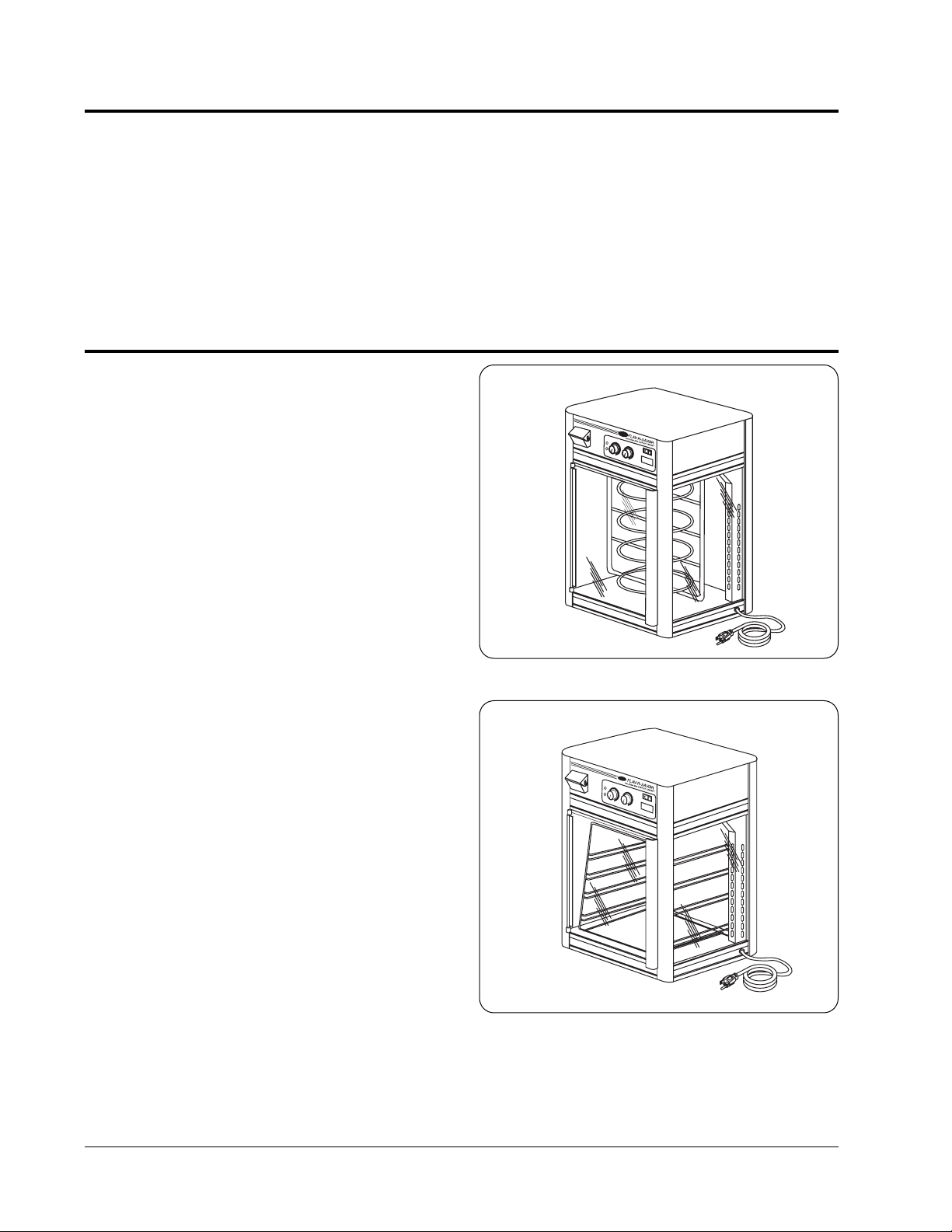
MODELS FSD-1 AND FSDT-1
The FSD-1 is a standard single door model with
revolving display motor. It has a revolving rack that
holds three or four display trays. The FSDT-1 is a
single door model with revolving display motor like
the FSD-1, but it is 5" (127 mm) taller and holds four
or five display trays.
MODELS FSD-1X AND FSDT-1X
The FSD-1X and FSDT-1X are similar to the FSD-1
and FSDT-1, but feature a st ationary rack instead of
a rotating rack.
MODELS FSD-2 AND FSDT-2
The FSD-2 and FSDT-2 are similar to the FSD-1
and FSDT-1, but have a convenient double door to
allow “pass-through” for production areas.
MODELS FSD-2X AND FSDT-2X
The FSD-2X and FSDT-2X are similar to the
FSD-1X and FSDT-1X featuring a stationary rack
instead of a rotating rack and also have a
convenient double door to allow “pass-through” for
production areas.
Figure 2. Model FSDT-1X
Figure 1. Model FSDT-1
CAUTIONS
Use only non-abrasive cleaners. Abrasive
cleaners could scratch the finish of your unit
marring its appearance and making it
susceptible to soil accumulation.
Water Quality Requirements - Incoming water in
excess of 3.0 grains of hardness per gallon
(GPG) (.75 grains of hardness per liter) must be
treated and softened before being used. Water
containing over 3.0 GPG (.75 GPL) will decrease
the efficiency and reduce the operating life of
the unit.
Page 5
3
SPECIFICATIONS
Form No. FSDM-1005
ELECTRICAL RATING CHART
The electrical information in the shaded areas pertains to Export models only.
Model Voltage Hertz Watts Amps Plug Configuration Shipping Weight
FSD-1 120 60 1440 12.0 NEMA 5-15P 113 lbs. (51 kg)
220 50/60 1440 6.5 CEE 7/7 Schuko 113 lbs. (51 kg)
240 50/60 1440 6.0 BS 1363 113 lbs. (51 kg)
220-230 (CE) 50/60 1440-1574 6.5-6.8 CEE 7/7 Schuko 113 lbs. (51 kg)
230-240 (CE) 50/60 1322-1440 5.8-6.0 BS 1363 113 lbs. (51 kg)
FSD-1X 120 60 1440 12.0 NEMA 5-15P 111 lbs. (50 kg)
220 50/60 1440 6.5 CEE 7/7 Schuko 111 lbs. (50 kg)
240 50/60 1440 6.0 BS 1363 111 lbs. (50 kg)
220-230 (CE) 50/60 1440-1574 6.5-6.8 CEE 7/7 Schuko 111 lbs. (50 kg)
230-240 (CE) 50/60 1322-1440 5.8-6.0 BS 1363 111 lbs. (50 kg)
FSD-2 120 60 1440 12.0 NEMA 5-15P 114 lbs. (52 kg)
220 50/60 1440 6.5 CEE 7/7 Schuko 114 lbs. (52 kg)
240 50/60 1440 6.0 BS 1363 114 lbs. (52 kg)
220-230 (CE) 50/60 1440-1574 6.5-6.8 CEE 7/7 Schuko 114 lbs. (52 kg)
230-240 (CE) 50/60 1322-1440 5.8-6.0 BS 1363 114 lbs. (52 kg)
FSD-2X 120 60 1440 12.0 NEMA 5-15P 112 lbs. (51 kg)
220 50/60 1440 6.5 CEE 7/7 Schuko 112 lbs. (51 kg)
240 50/60 1440 6.0 BS 1363 112 lbs. (51 kg)
220-230 (CE) 50/60 1440-1574 6.5-6.8 CEE 7/7 Schuko 112 lbs. (51 kg)
230-240 (CE) 50/60 1322-1440 5.8-6.0 BS 1363 112 lbs. (51 kg)
FSDT-1 120 60 1440 12.0 NEMA 5-15P 120 lbs. (54 kg)
220 50/60 1440 6.5 CEE 7/7 Schuko 120 lbs. (54 kg)
240 50/60 1440 6.0 BS 1363 120 lbs. (54 kg)
220-230 (CE) 50/60 1440-1574 6.5-6.8 CEE 7/7 Schuko 120 lbs. (54 kg)
230-240 (CE) 50/60 1322-1440 5.8-6.0 BS 1363 120 lbs. (54 kg)
FSDT-1X 120 60 1440 12.0 NEMA 5-15P 118 lbs. (51 kg)
220 50/60 1440 6.5 CEE 7/7 Schuko 118 lbs. (51 kg)
240 50/60 1440 6.0 BS 1363 118 lbs. (51 kg)
220-230 (CE) 50/60 1440-1574 6.5-6.8 CEE 7/7 Schuko 118 lbs. (51 kg)
230-240 (CE) 50/60 1322-1440 5.8-6.0 BS 1363 118 lbs. (51 kg)
FSDT-2 120 60 1440 12.0 NEMA 5-15P 122 lbs. (55 kg)
220 50/60 1440 6.5 CEE 7/7 Schuko 122 lbs. (55 kg)
240 50/60 1440 6.0 BS 1363 122 lbs. (55 kg)
220-230 (CE) 50/60 1440-1574 6.5-6.8 CEE 7/7 Schuko 122 lbs. (55 kg)
230-240 (CE) 50/60 1322-1440 5.8-6.0 BS 1363 122 lbs. (55 kg)
FSDT-2X 120 60 1440 12.0 NEMA 5-15P 120 lbs. (54 kg)
220 50/60 1440 6.5 CEE 7/7 Schuko 120 lbs. (54 kg)
240 50/60 1440 6.0 BS 1363 120 lbs. (54 kg)
220-230 (CE) 50/60 1440-1574 6.5-6.8 CEE 7/7 Schuko 120 lbs. (54 kg)
230-240 (CE) 50/60 1322-1440 5.8-6.0 BS 1363 120 lbs. (54 kg)
NOTE: Shipping weight includes packaging.
Page 6
4
SPECIFICATIONS
Form No. FSDM-1005
Width Depth Height
Model (A) (B) (C)
*
FSD-1 22-1/2" 24" 27-1/2"
(572 mm) (610 mm) (699 mm)
FSD-1X 22-1/2" 24" 27-1/2"
(572 mm) (610 mm) (699 mm)
FSD-2 22-1/2" 25-1/8" 27-1/2"
(572 mm) (638 mm) (699 mm)
FSD-2X 22-1/2" 25-1/8" 27-1/2"
(572 mm) (638 mm) (699 mm)
FSDT-1 22-1/2" 24" 32-1/2"
(572 mm) (610 mm) (826 mm)
FSDT-1X 22-1/2" 24" 32-1/2"
(572 mm) (610 mm) (826 mm)
FSDT-2 22-1/2" 25-1/8" 32-1/2"
(572 mm) (638 mm) (826 mm)
FSDT-2X 22-1/2" 25-1/8" 32-1/2"
(572 mm) (638 mm) (826 mm)
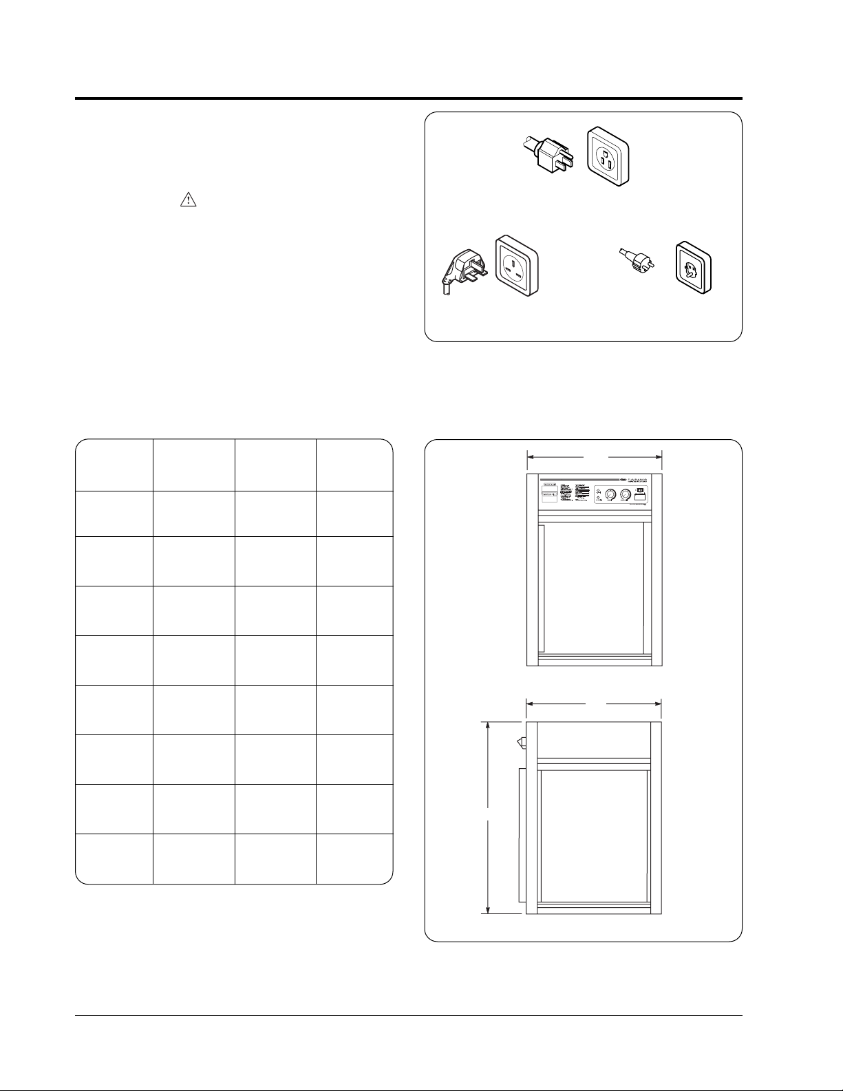
DIMENSIONS
A
B
C
Cabinet Openings:
FSD models: 19"W x 18-5/8"H (483 x 473 mm)
FSDT models: 19"W x 23-3/4"H (483 x 603 mm)
*Add 1" (25 mm) to height for display sign.
Figure 4. Dimensions
PLUG CONFIGURATION
Units are supplied from the factory with an electrical
cord and plug installed. Plugs are supplied
according to the applications. (See Figure 3.)
WARNING
Plug unit into a properly grounded electrical
outlet of the correct voltage, size and plug
configuration. If the plug and receptacle do not
match, contact a qualified electrician to
determine the proper voltage and size and install
the proper electrical outlet.
NEMA 5-15P
BS-1363 CEE 7/7 Schuko
Figure 3. Plug Configurations
Page 7

5
INSTALLATION
Form No. FSDM-1005
UNPACKING
The Flav-R-Savor Holding and Display Cabinets are
shipped with most components installed and ready
for operation. The following installation instructions
must be performed before plugging in and operating
the cabinet.
WARNING
Do not lay unit on the side with the control panel
or damage to the unit could occur.
WARNING
To prevent any injury or damage to the unit do
not pull unit by power cord.
1. Remove unit from box.
2. Remove information packet. To prevent delay
in obtaining warranty coverage, fill out and
mail in the warranty card.
3. Remove tape and protective film from all
surfaces of unit.
4. The stainless steel floor in all Flav-R-Savor units
is protected during shipping with a sheet of
corrugated cardboard. This protection must be
removed prior to cabinet operation.
5. The plated display racks have packing material
and cardboard attached for protection during
shipping. This protection must be removed prior
to cabinet operation.
6. The Flav-R-Savor Holding and Display Cabinets
have tempered glass panels that are protected
and secured during shipping by rubber tabs
and/or foam tape along the glass edges. These
tabs and foam tape must be removed prior to
cabinet operation.
To remove a glass panel, grasp the panel firmly
from inside and outside of the cabinet, lift up and
out of the bottom channel, then carefully lower
glass panel until it clears the upper channel.
To reinstall, position glass panel top edge under
the cabinet lip, raise panel until it clears the
bottom channel, then carefully lower the panel
until it rests in the bottom channel.
Figure 5. FSD & FSDT Models
Rotating
Pizza Tier
Rack
Stationary
Rack
Decal
Drain Tube
Coupling and Cotter Pins
Front Access Door*
Rear Access Door
Air Distribution Duct
Lens Cover
Display Light
Side Glass Panel
* FSD-2X & FSDT-2X models only.
7. If your unit was ordered with Merchandising
Decal Graphics, see ACCESSORIES for
installation instructions.
If your unit is equipped with the optional
Merchandising Display Sign, see
ACCESSORIES for installation instructions.
If installing the optional Stacking Kit, see
ACCESSORIES for installation instructions.
Page 8

6
INSTALLATION
Form No. FSDM-1005
LOCATION
WARNING
For safe and proper operation, the unit must be
located a reasonable distance from combustible
walls and materials. If safe distances are not
maintained, discoloration or combustion could
occur.
CAUTION
To avoid any injury or damage locate the
Holding Cabinet at the proper counter height, in
an area that is convenient for use. The location
should be level to prevent the unit or its
contents from accidentally falling, and strong
enough to support the weight of the unit and
food.
CAUTION
The unit must be transported in an upright
position. If laid on its side, the water must be
drained from the unit.
CAUTION
The National Sanitation Foundation (NSF)
requires that units over 36" (914 mm) in length
or weighing more than 80 lbs. (36 kg) to be either
sealed or raised on the installation surface. If
this unit cannot be sealed at the point of use, 4"
(102 mm) legs are included to allow for proper
cleaning access below unit.
NOTE: The unit must be transported in the upright
position. If laid on its side, all glass surfaces must be
secured with tape, and water must be drained from
the unit. See DRAINING THE RESERVOIR in the
MAINTENANCE section.
REVERSIBLE ACCESS DOOR
1. Remove hinge pivot pin from top of door left side
and carefully remove door from hinges. Do not
lose plastic washer located under bottom hinge
pin.
2. Swap the door hinges with the strike plates on
the right side using original hardware.
3. Reinstall hinge pivot pin to door removed in
step 1.
4. Rotate the door 180° and remove other hinge
pin.
5. Place plastic washer on bottom hinge pin and
install door into hinges. Install top hinge pivot pin
and tighten securely.
NOTE: See RELOCATING PROXIMITY SWITCH
when reversing a door.
Figure 6. Reversible Access Door
Bottom HInge
Pivot Pin
Door Mounting Hinge
Top Hinge Pin
Strike Plate
Page 9

7
INSTALLATION
Form No. FSDM-1005
RELOCATING PROXIMITY SWITCH
(Rotating Rack Models Only—FSD-1,
FSDT-1, FSD-2, FSDT-2)
(See Figure 7)
FSD Models equipped with rotating rack will require
relocating the proximity switch(es) when reversing
the door(s).
The proximity switch stops the rack from rotating
when the door is opened. Follow these steps listed
so the proximity switch is in the proper position after
reversing the door(s). Unit requires one switch per
door.
1. Remove the 4 screws and top cover.
2. Remove the screw and nut securing the
proximity switch to the cabinet. The screw is
accessed from inside the cabinet. Reinstall
screw and nut into hole after removing switch.
3. Cut the cable tie securing the proximity switch
wires to the wiring harness. Mark the two wires
for reassembly and unplug the wires from the
proximity switch. Route the wires to the opposite
corner and reattach the wires to the switch.
Figure 7. Relocating Proximity Switch
4. Remove the screw and nut from the new
mounting hole. Using opposite hole on switch,
secure the proximity switch to the mounting hole
with the screw and nut.
Make sure to maintain switch orientation when
tightening hardware.
5. Make sure wires do not interfere with other
components inside the cabinet then secure
switch wires to wiring harness with a cable tie
(not supplied).
NOTE: On models equipped with two doors, it may
be necessary to move the air chamber to access the
proximity switch on the customer side door. Drain all
water from the unit, remove the drain plug from
inside the cabinet, and remove four screws securing
air chamber assembly to the cabinet. Carefully
move air chamber out of the way to access proximity
switch. Reassemble after relocating switch.
6. Install cover and four screws.
Screw
Proximity Switch
Mounting with Door
Opening from Left-
Hinged Right
Proximity Switch
Mounting with Door
Opening from Right-
Hinged Left
Page 10

8
OPERATION
Form No. FSDM-1005
WARNING
Some exterior surfaces on the unit will get hot.
Use caution when touching these areas to avoid
injury.
WARNING
To prevent any injury, discontinue use if power
cord is frayed or worn.
CAUTION
Unit is not weatherproof. For safe and proper
operation the unit must be located indoors
where the ambient air temperature is a minimum
of 70°F (21°C) and a maximum of 85°F (29°C).
1. Plug unit into an electrical outlet of the correct
voltage, size and plug configuration. See
SPECIFICATIONS for details.
2. Turn the Power Switch on the control panel to
the ON position. The indicators will light up at
this time. (See Figure 8.)
3. Fill the water reservoir with softened or distilled
water. To fill the reservoir, lift the fill cup cover up
and pull forward. Slowly pour the water into the
cup until the red Low Water Indicator goes off.
Use of softened or distilled water is
recommended to preserve the life of the
electrical and mechanical components in the
reservoir. Do not use deionized water. If “hard”
water is used, the reservoir will require periodic
cleaning and deliming. (See MAINTENANCE for
removing lime and mineral deposits.)
NOTE: On the initial fill, the water reservoir capacity
is one gallon (3.8 liters).
4. Set the Humidity Control and Temperature
Control to the desired level. See the FOOD
HOLDING GUIDE for recommendations.
NOTE: T emperature and humidity settings may vary
depending upon product make-up and consistency.
The cabinet temperature indicator displays the
lowest temperature point inside the cabinet, not the
product temperature.
5. Allow 30 minutes to preheat a full reservoir of
water. The green Humidity Cycle Indicator will go
off when the interior of the cabinet has reached
the selected humidity setting. The Flav-R-Savor
cabinet is then ready to hold foods at the
humidity and temperature selected.
The reservoir capacity permits uninterrupted
operation for approximately 4-8 hours, depending
on the settings and how frequently the door is
opened. When the red Low Water Indicator is lit,
add water to the reservoir.
NOTE: Product failure due to lime or mineral
deposits is not covered under warranty.
Figure 8. Control Panel
Water Reservoir
Fill Cup
Temperature
Control
Cabinet
Temperature
Indicator
Humidity
Control
Low Water
Indicator
Humidity Cycle
Indicator
Power
Switch
Page 11

9
OPERATION
Form No. FSDM-1005
MAINTENANCE
Maximum Humidity Temperature
Type of Food Holding Time Setting Setting °F °C
Bagels 3 Hours Low 4 140 60
Biscuits 2 Hours Medium 3 130 54
Chicken - Parts 5 Hours High 5 175 79
Chicken - Whole 2 Hours High 5.5 180 82
Croissants 3 Hours Low 4 140 60
Fish 1 Hour Medium 5.5 180 82
Frankfurters 2 Hours High 6 185 85
Fruit Pies 3.5 Hours Medium 4 140 60
Hot Dogs (Appetizers) 4 Hours High 5 175 79
Onion Rings 1 Hour Low 4 140 60
Pizza 1 Hour Medium 6 185 85
Pretzels 3 Hours Medium 4 140 60
Ribs 2 Hours High 6 185 85
Wrapped Sandwiches 2 Hours Medium 4.5 160 71
FOOD HOLDING GUIDE
NOTE: All times and settings are recommendations only and may vary depending on product preparation,
cooking time and internal food temperature.
GENERAL
The Hatco Flav-R-Savor Holding & Display
Cabinets are designed for maximum durability and
performance, with minimum maintenance.
WARNING
To avoid any injury, turn the power switch OFF,
unplug the unit from the power source and allow
to cool before performing any maintenance.
CLEANING
WARNING
To avoid electrical shock or personal injury, do
not steam clean or use excessive water on the
unit.
WARNING
Unit is not waterproof. DO NOT submerge in
water. Do not operate if it has been submerged
in water.
To preserve the bright finish of the Flav-R-Savor
cabinet, it is recommended that the exterior and
interior surfaces be wiped daily with a damp cloth.
Food pans should be removed and washed. Air
distribution duct is removable for cleaning. Stubborn
stains may be removed with a good stainless steel
cleaner or a non-abrasive cleaner. Hard to reach
areas should be cleaned with a small brush and mild
soap.
CAUTION
Use only non-abrasive cleaners. Abrasive
cleaners could scratch the finish of your unit
marring its appearance and making it
susceptible to soil accumulation.
Clean the glass sides using a common glass
cleaner. For hard-to-clean stains, removal of the
glass is suggested.
Removing Glass
1. Lift the glass to be cleaned from the bottom of
the cabinet.
2. Pull the lower edge away from the cabinet.
3. Carefully lower the glass until the top clears the
cabinet.
Page 12

10
MAINTENANCE
Form No. FSDM-1005
NOTE: The drain hose assembly is located in the
corner of the cabinet inside the rear door.
NOTE: Position a container to hold the water while
draining.
NOTE: T o ease installation, moisten the inside of the
drain hose end with water before installing.
1. Insert the drain hose fitting into the water outlet,
located on the ceiling of the cabinet. Once the
fitting is installed, water will begin to drain from
the hose. (See Figure 10.)
2. Once the unit has finished draining, the drain
tube assembly can be removed by pressing the
release tab and gently pulling the fitting out.
3. Place the drain tube back into the holding clips
inside the rear door.
Figure 9. Rotating Rack
Figure 10. Draining Reservoir
Cotter Pins
Coupling
Drain Hose
Water Outlet
Installing Glass
1. Position the glass with the top edge under the
cabinet lip and raise the glass until it clears the
bottom channel of the cabinet.
2. Move the bottom of the glass towards the cabinet
until the glass rests against the cabinet frame.
3. Carefully lower the glass until it rests in the
bottom channel of the cabinet.
Removing Rotating Rack
(Models FSD-1, FSDT-1, FSD-2, FSDT-2)
1. Open the front access door.
2. Remove the two cotter pins from the rotating
rack coupling located at the top of the rack inside
the cabinet. (See Figure 9.)
3. Lower the connecting coupling until it is free of
the motor shaft and remove the rack from the
cabinet.
Installing Rotating Rack
(Models FSD-1, FSDT-1, FSD-2, FSDT-2)
1. With the coupling on the rack, insert the rack into
the cabinet through the access door and place
the rack bottom point in the dimple located at the
center of the cabinet floor.
2. Slide the rack coupling up onto the motor shaft
and align the coupling holes.
3. Insert the two cotter pins through the coupling
and shaft.
WARNING
Units with a motorized rotating style display use
safety door switches that turn the rotating rack
off when a door is opened. If the rack rotates
when a door is opened, unplug the unit and
contact your Authorized Service Agent for
service.
DRAINING THE RESERVOIR
WARNING
To avoid any injury, turn the power OFF to the
unit and allow to cool before draining.
It is recommended that the Flav-R-Savor water
reservoir be drained prior to moving the cabinet and
after removing lime or mineral deposits from the
water reservoir.
Page 13

11
MAINTENANCE
Form No. FSDM-1005
DISPLAY LIGHT BULB REPLACEMENT
WARNING
Only light bulbs which meet or exceed N.S.F.
standards, specifically designed for food
holding areas must be used. Breakage of light
bulbs not specially coated or covered could
result in personal injury and/or food
contamination.
WARNING
Be sure the protective lens cover for the light
bulbs are installed. Breakage of a bulb not
properly covered could result in personal injury
and/or food contamination.
The unit is equipped with two 120 Volt fluorescent
light tubes which illuminate the warming area. These
tubes have a special lens cover to guard against
injury and food contamination in the event of
breakage. When replacing a fluorescent light, use
Hatco part #02.30.074.00.
To replace a fluorescent light, disconnect the power
supply and wait until the unit has cooled. Remove
the protective lens cover from the fixture and then
carefully twist the fluorescent tube and gently pull to
remove it from the sockets.
REMOVING LIME & MINERAL
DEPOSITS
CAUTION
Water Quality Requirements - Incoming water in
excess of 3.0 grains of hardness per gallon
(GPG) (.75 grains of hardness per liter) must be
treated and softened before being used. Water
containing over 3.0 GPG (.75 GPL) will decrease
the efficiency and reduce the operating life of
the unit.
NOTE: Product failure caused by liming or sediment
buildup is not covered under warranty.
NOTE: If the water used has an excessive amount
of lime or mineral content, follow the instructions
listed below for periodic cleaning and deliming of the
water reservoir.
1. Turn the power switch off and unplug the unit
from its power source.
2. After the unit has cooled down, drain all
remaining water out of the unit. See DRAINING
THE RESERVOIR.
3. Fill the unit with a mixture of water and delimer.
NOTE: The delimer used should be a safe, nontoxic, non-corrosive solution. Follow the delimer’s
instruction for proper mixture of water and delimer
solution.
4. Allow the unit to stand with the mixture in the
reservoir for the recommended period of time.
(The time required will vary depending on the
solution used and amount of deposits in the
reservoir.)
5. After the deliming period, drain the solution from
the tank.
6. Continue to fill and drain the unit with water only,
until the discharge is clear and all deliming
solution has been removed and rinsed.
7. Plug the cabinet power cord into its power source
and fill the unit as usual for daily operation.
NOTE: How often this procedure must be performed
depends on the lime and mineral content of the
water used for daily operation.
WARNING
If service is required on this unit, contact your
Authorized Hatco Service Agent, or contact the
Hatco Service Department at 800-558-0607 or
414-671-6350; fax 800-690-2966 or International
fax 414-671-3976.
WARNING
This product has no “user” serviceable parts. To
avoid damage to the unit or injury to personnel,
use only Authorized Hatco Service Agents and
Genuine Hatco Parts when service is required.
WARNING
Genuine Hatco Replacement Parts are specified
to operate safely in the environments in which
they are used. Some aftermarket or generic
replacement parts do not have the
characteristics that will allow them to operate
safely in Hatco equipment. It is essential to use
Hatco Replacement Parts when repairing Hatco
equipment. Failure to use Hatco Replacement
Parts may subject operators of the equipment to
hazardous electrical voltage, resulting in
electrical shock or burn.
Page 14

12
ACCESSORIES
Form No. FSDM-1005
Figure 11. Stacking Kit
STACKING KIT
Special brackets are available for stacking one unit
on top of another. This stacking hardware secures
the top unit to the lower unit. Holes must be drilled
into both units and brackets attached using
hardware supplied. (See Figure 11.)
ADJUSTABLE LEGS
4" (102 mm) adjustable legs are available for the
units. Legs mount in holes at bottom corners of
cabinet. (See Figure 12.)
MERCHANDISING DISPLAY SIGN
Merchandising Display Signs, which include the
metal holder, acrylic window and printed sign are
available to promote Pizza, Chicken or Fish food
products. Install holder on one of three sides of the
cabinet top.
1. Remove the existing screws securing the top
cover in place, position the sign holder over the
screw holes and reinstall the screws.
(See Figure 13.)
2. Place the printed sign in the holder and slide the
protective acrylic window over the sign.
MERCHANDISING FOOD GRAPHICS
Graphic decals feature food illustrations only and
are available for Pizza, Chicken, Pretzel and
Croissant/Biscuits. Install decals on three sides of
the cabinet above the glass panels.
1. Clean the stainless steel side panels with a nonoily cleaner, such as isopropyl alcohol (rubbing
alcohol).
2. When sides are dry, simply remove the
protective backing from the decal and apply to
the panel.
3. Remove air pockets by rubbing gently with a soft
cloth from the center towards the outer edges.
PANS
Aluminum half-size bun pans 18" x 13"
(457 x 330 mm) are available for the stationary style
racks.
Aluminum Pizza pans are available in 14" (356 mm),
15" (381 mm), 16" (406 mm) and 18" (457 mm)
diameters which fit all of the rotating style racks.
Figure 13. Display Sign
Leg Adjustment
Adjust leg using a 9/16" (14 mm)
open-end wrench and turning
bottom of leg accordingly.
Leg Installation
Figure 12. Adjustable Legs
Page 15

13
ACCESSORIES
Form No. FSDM-1005
Figure 14. Display Racks - FSD Only
DISPLAY RACKS
A wide assortment of plated racks are available to
“customize” the Flav-R-Savor to your foodservice
operation.
FSD Only (See Figure 14)
5-Shelf Multi-Purpose Rack, Model - FS5SMPACC
3-Tier Circle Rack, Model - FSD3TCRACC
3-Tier Pan Rack, Model - FS3TPRACC‡
FSDT Only (See Figure 15)
7-Shelf Multi-Purpose Rack, Model - FST7SMP ACC
4-Tier Circle Rack, Model - FSDT4TCRACC
5-Tier Circle Rack, Model - FSDT5TCRACC
4-Tier Pan Rack, Model - FST4TPRACC‡
3-Shelf Angle Rack, Model - FST3SARACC
5-Shelf Angle Rack, Model - FST5SARACC
3-Tier Pretzel Tree, Model - FSDT3TPTACC
‡
Accommodates half-size bun pans, not included.
DESIGNER COLORS
Choose from warm red, black, gray granite, white
granite, hunter green or navy blue powdercoated
cabinet colors to blend into any decor. Only
available at time of purchase.
5-Shelf Multi-Purpose Rack
Model FS5SMPACC
Shelf 1: 2-3/4" (70 mm) on center.
NOTE: Shelf 1 is the bottom shelf.
Shelf 2: 3" (76 mm) on center.
Shelf 3: 3" (76 mm) on center.
Shelf 4: 3-1/4" (83 mm) on center.
Shelves #2, 3 & 4 are removable.
3-Tier Circle Rack
Model FSD3TCRACC
Top Tier: 5" (127 mm) on center.
All others: 5-1/4" (133 mm) on center.
3-Tier Pan Rack
Model FS3TPRACC‡
Top Tier: 4" (102 mm) on center.
All others: 4-1/4" (108 mm)
on center.
Figure 15. Display Racks - FSDT Only
3-Shelf Angle Rack
Model FST3SARACC
Top Tier: 5" (127 mm) on center.
All others: 5-1/4" (133 mm) on center.
Middle shelf is removable.
Rack shelves slant at 15° angle.
5-Shelf Angle Rack
Model FST5SARACC
All Shelves 3-3/4"
(95 mm) on center.
All shelves are removable.
3-Tier Pretzel Tree
Model FSDT3TPTACC
Top Two Tiers: 6" (152 mm)
on center.
Bottom Tier: 7" (178 mm)
on center.
4-Tier Circle Rack
Model FSDT4TCRACC
Top Two Tiers: 5" (127 mm)
on center.
Bottom Two Tiers: 5-1/4"
(133 mm) on center.
5-Tier Circle Rack
Model FSDT5TCRACC
All Tiers 4" (102 mm)
on center.
4-Tier Pan Rack
Model FST4TPRACC‡
Top Tier: 4" (102 mm)
on center.
All others: 4-1/4" (108 mm)
on center.
7-Shelf Multi-Purpose Rack
Model FST7SMPACC
Shelves 1 & 5: 2-3/4" (70 mm) on center.
NOTE: Shelf 1 is the bottom shelf.
Shelves 2, 3 & 6: 3" (76 mm) on center.
Shelf 4: 3-1/4" (83 mm) on center.
Shelves #2, 3, 4, 6 & 7 are removable.
Page 16

14
HATCO LIMITED WARRANTY
Form No. FSDM-1005
1. PRODUCT WARRANTY
Hatco warrants the products that it manufactures
(the “Products”) to be free from defects in
materials and workmanship, under normal
use and service, for a period of one (1) year from
the date of purchase when installed and
maintained in accordance with Hatco’s written
instructions or 18 months from the date of
shipment from Hatco. Buyer must establish the
product’s purchase date by returning Hatco’s
Warranty Registration Card or by other means
satisfactory to Hatco in its sole discretion.
Hatco warrants the following Product components
to be free from defects in materials and
workmanship from the date of purchase (subject
to the foregoing conditions) for the period(s) of
time and on the conditions listed below:
a) One (1) Year Parts and Labor PLUS One
(1) Additional Year Parts-Only Warranty:
Toaster Elements (metal sheathed)
Drawer Warmer Elements (metal sheathed)
Drawer Warmer Drawer Rollers and Slides
Food Warmer Elements (metal sheathed)
Display Warmer Elements (met al sheathed
air heating)
Holding Cabinet Elements (metal sheathed
air heating)
b) One (1) Year Parts and Labor PLUS Four
(4) Years Parts-Only Warranty on
pro-rated terms that Hatco will explain
at Buyer’s request:
3CS and FR Tanks
c) One (1) Year Parts and Labor PLUS Nine
(9) Years Parts-Only Warranty on:
Electric Booster Heater Tanks
Gas Booster Heater Tanks
THE FOREGOING WARRANTIES ARE
EXCLUSIVE AND IN LIEU OF ANY OTHER
WARRANTY, EXPRESSED OR IMPLIED,
INCLUDING BUT NOT LIMITED TO ANY
IMPLIED WARRANTY OF MERCHANTABILITY
OR FITNESS FOR A PARTICULAR PURPOSE
OR PATENT OR OTHER INTELLECTUAL
PROPERTY RIGHT INFRINGEMENT. Without
limiting the generality of the foregoing, SUCH
WARRANTIES DO NOT COVER: Coated
incandescent light bulbs, fluorescent lights, lamp
warmer heat bulbs, glass components, Product
failure in booster tank, fin tube heat exchanger, or
other water heating equipment, caused
by liming, sediment buildup, chemical attack or
freezing, Product misuse, tampering or
misapplication, improper installation or application of
improper voltage.
2. LIMITATION OF REMEDIES AND
DAMAGES
Hatco’s liability and Buyer’s exclusive remedy
hereunder will be limited solely, at Hatco’s option,
to repair or replacement by a Hatco-authorized
service agency (other than where Buyer is
located outside of the United States, Canada,
United Kingdom or Australia in which case
Hatco’s liability and Buyer’s exclusive remedy
hereunder will be limited solely to replacement of
part under warranty) with respect to any claim
made within the applicable warranty period
referred to above. Hatco reserves the right to
accept or reject any such claim in whole or in part.
Hatco will not accept the return of any Product
without prior written approval from Hatco, and all
such approved returns shall be made at Buyer’s
sole expense. HATCO WILL NOT BE LIABLE,
UNDER ANY CIRCUMSTANCES, FOR
CONSEQUENTIAL OR INCIDENTAL
DAMAGES, INCLUDING BUT NOT LIMITED TO
LABOR COSTS OR LOST PROFITS
RESUL TING FROM THE USE OF OR INABILITY
TO USE THE PRODUCTS OR FROM THE
PRODUCTS BEING INCORPORATED IN OR
BECOMING A COMPONENT OF ANY OTHER
PRODUCT OR GOODS.
Page 17

Form No. FSDM-1005
15
NOTES
Form No. FSDM-1005
Page 18

Form No. FSDM-1005
16
NOTES
Page 19

Form No. FSDM-1005
17
NOTES
Form No. FSDM-1005
Page 20

HATCO CORPORATION
P.O. Box 340500, Milwaukee, WI 53234-0500 U.S.A.
(800) 558-0607 (414) 671-6350
Parts & Service Fax (800) 690-2966 Int’l. Fax (414) 671-3976
www.hatcocorp.com
HATCO AUTHORIZED PARTS DISTRIBUTORS
Printed in U.S.A. October 2005
ALABAMA
Jones McLeod Appl. Svc.
Birmingham 205-251-0159
ARIZONA
Auth. Comm. Food Equip.
Phoenix 602-234-2443
Byassee Equipment Co.
Phoenix 602-252-0402
CALIFORNIA
Industrial Electric
Huntington Beach 714-379-7100
Chapman Appl. Service
San Diego 619-298-7106
P & D Appliance
S. San Francisco 650-635-1900
COLORADO
Hawkins Commercial Appliance
Englewood 303-781-5548
DELA
WARE
Food Equipment Service
Wilmington 302-996-9363
FLORIDA
Whaley Foodservice Repair
Jacksonville 904-725-7800
Universal Restaurant Services
Miami 305-593-5488
Nass Service Co., Inc.
Orlando 407-425-2681
B.G.S.I.
Pompano Beach 954-971-0456
Comm. Appliance Service
Tampa 813-663-0313
GEORGIA
TWC Services
Smyrna 770-438-9797
Heritage Service Group
Norcross 866-388-9837
Southeastern Rest. Svc.
Norcross 770-446-6177
HA
WAII
Burney’s Comm. Service, Inc.
Honolulu 808-848-1466
Food Equip Parts & Service
Honolulu 808-847-4871
ILLINOIS
Parts Town
Lombard 708-865-7278
Eichenauer Elec. Service
Decatur 217-429-4229
Midwest Elec. Appl. Service
Elmhurst 630-279-8000
Cone’s Repair Service
Moline 309-797-5323
INDIANA
GCS Service
Indianapolis 317-545-9655
IOW
A
Electric Motor Service Co.
Davenport 319-323-1823
Goodwin Tucker Group
Des Moines 515-262-9308
KENTUCKY
GCS Service
Louisville 502-367-1788
LOUISIANA
Chandlers Parts & Service
Baton Rouge 225-272-6620
MAR
YLAND
Electric Motor Service
Baltimore 410-467-8080
GCS Service
Silver Spring 301-585-7550
MASSACHUSETTS
Ace Service Co., Inc.
Needham 781-449-4220
MICHIGAN
Commercial Kitchen Service
Bay City 517-893-4561
Bildons Appliance Service
Detroit 248-478-3320
Midwest Food Equip. Service
Grandville 616-261-2000
MINNESOT
A
GCS Service
Minneapolis 612-546-4221
MISSOURI
General Parts
Kansas City 816-421-5400
Commercial Kitchen Services
St. Louis 314-890-0700
Kaemmerlen Parts & Service
St. Louis 314-535-2222
NEBRASKA
Anderson Electric
Omaha 402-341-1414
NEV
ADA
Burney’s Commercial
Las Vegas 702-736-0006
Hi. Tech Commercial Service
N. Las Vegas 702-649-4616
NEW JERSEY
Jay Hill Repair
Fairfield 973-575-9145
Service Plus
Flanders 973-691-6300
NEW
YORK
Acme American Repairs, Inc.
Brooklyn 718-456-6544
Alpro Service Co.
Brooklyn 718-386-2515
Appliance Installation
Buffalo 716-884-7425
Northern Parts Dist.
Plattsburgh 518-563-3200
J.B. Brady, Inc.
Syracuse 315-422-9271
NORTH CAROLINA
Authorized Appliance
Charlotte 704-377-4501
OHIO
Akron/Canton Comm. Svc. Inc.
Akron 330-753-6635
Certified Service Center
Cincinnati 513-772-6600
Commercial Parts and Service
Columbus 614-221-0057
Electrical Appl. Repair Service
Independence 216-459-8700
E. A. Wichman Co.
Toledo 419-385-9121
OKLAHOMA
Hagar Rest. Service, Inc.
Oklahoma City 405-235-2184
Krueger, Inc.
Oklahoma City 405-528-8883
OREGON
Ron’s Service, Inc.
Portland 503-624-0890
PENNSYL
VANIA
Elmer Schultz Services
Philadelphia 215-627-5401
FAST Comm. Appl. Service
Philadelphia 215-288-4800
GCS Service
Pittsburgh 412-787-1970
K & D Service Co.
Harrisburg 717-236-9039
Electric Repair Co.
Reading 610-376-5444
RHODE ISLAND
Marshall Electric Co.
Providence 401-331-1163
SOUTH CAROLINA
Whaley Foodservice Repair
W. Columbia 803-791-4420
TENNESSEE
Camp Electric
Memphis 901-527-7543
TEXAS
Stove Parts Supply
Fort Worth 817-831-0381
Armstrong Repair Service
Houston 713-666-7100
Commercial Kitchen Repair Co.
San Antonio 210-735-2811
UT
AH
La Monica’s Rest. Equip. Service
Murray 801-263-3221
VIRGINIA
Daubers
Norfolk 757-855-4097
Daubers
Springfield 703-866-3600
W
ASHINGTON
Restaurant Appl. Service
Seattle 206-524-8200
WISCONSIN
A.S.C., Inc.
Madison 608-246-3160
A.S.C., Inc.
Milwaukee 414-543-6460
CANADA
BRITISH COLUMBIA
Key Food Equipment Service
Vancouver 604-433-4484
MANIT
OBA
Denko Mechanical Ltd.
Winnipeg 204-233-8003
ONT
ARIO
R.G. Henderson Ltd.
Toronto 416-422-5580
Choquette CKS
Ottawa 613-739-8458
QUÉBEC
Choquette CKS
Montreal 514-722-2000
Choquette CKS
Québec City 418-681-3944
Part No. 07.04.289.00 Form No. FSDM-1005
 Loading...