

Page 1
OPERATING INSTRUCTIONS &
REPLACEMENT PARTS LIST
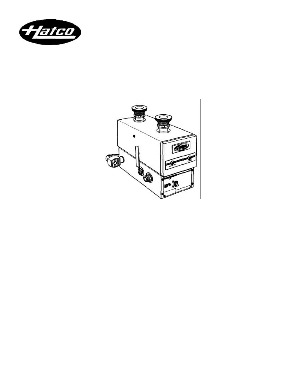
BURGER KING STEAMER
Model FR-5C
HATCO CORPORATION MILWAUKEE, Wl 53234 U.S.A. (414) 671 -6350
Page 2
OPERATING PROCEDURES Model FR-5C
Installation, maintenance and repair to be per-
formed by qualified service personnel only.
SAFETY PRECAUTIONS
Do not turn on electrical current to the heater until
the holding vessel has been filled with water. Drain
holding vessel with power "Off" or element burn out
could occur.
To prevent electrical shock, never service the
heater without first turning off the power at the fused
disconnect switch or the circuit breaker.
To prevent electric shock, always turn off the power
to the unit before performing cleaning or deliming.
ELECTRICAL SPECIFICATIONS
Voltage Wattage Amps Phase
208 3250 15.6 1
240 3250 13.5 1
*220/380 4095 18.6 3
*For Export use only.
WARNING: For proper electrical installation, con-
forming to local electrical codes, consult a licensed
electrical contractor. Refer to the specification plate on
the front of the heater for voltage requirements.
OPERATING PROCEDURE
1. Close sump valve by moving and raising the handle,
forward.
NOTE: Sump valve is closed when the handle is vertical.
2. Make sure the holding vessel is filled with water to the
normal operating level.
3. Turn the toggle switch to the "ON" position. The power
"ON" light will glow indicating power is supplied. The
"Water at Temperature" light will glow when water is at
the preset control temperature.
NOTE: All Hatco FR-5C heaters have an energy cut-off
switch (ECO) that will shut "OFF" the power if the unit
should overheat. To reset, wait for the unit to cool, then
push the red reset button on the front of the heater.
NOTE: All Hatco FR-5C heaters have a low water cut-off
that will shut "OFF" the power to the unit if the water level
is too low for proper operation. The unit will return to normal operation once the proper water level is restored.
WARNING: Service or repair must be performed by
qualified service personnel only.
STEAMER CLEANING INSTRUCTIONS - DAILY
1. Turn power off.
2. Drain water by pushing drain handle backwards.
3. Remove top cover, slide doors, wire racks, trays, bot
torn deflector and strainers from steamer tank and
wash them at the pot sinks.
4. Place rubber stopper in front tank opening to prevent
debris from falling into heater compartment. Wipe
visible deposits from tank and make sure the water
sensor on the side of the tank is also clean. Wash
remaining residue into the rear sump compartment and
out the drain.
5. Close valve by raising handle forward. Remove stopper.
6. Dissolve a one ounce package of K-5 sanitizer in 2 1/2
gallons (9.5 liters) of warm water. Pour solution in tank.
Allow solution to stand for 5 minutes.
7. Drain tank and leave valve open.
8. Place rubber stopper in rear tank opening.
9. Use a hose and hose adapter in front tank opening to
power flush the unit.
10. Reverse stopper and hose and flush through rear tank
opening.
11. Repeat procedure, alternating as necessary, until
clean. Rinse all areas with fresh water.
12. Remove rubber stopper, hose adapter and close valve.
13. Replace strainers, bottom deflector, wire racks, doors
and top cover, insuring they are installed properly.
DELIMER CLEANING INSTRUCTIONS - WEEKLY
1. Mix one packet of delimer in one pint (.5 liter) of hot
water and fill steam chamber and water level tank with
solution.
2. Let solution remain in chamber and water level tank for
at least 15 minutes.
3. Drain delimer solution.
4. If deposits remain, make up fresh delimer solution and
repeat procedure.
5. Rinse with clear water until all of the delimer solution
has been rinsed away.
6. Then follow sanitizing procedure under daily cleaning
instructions.
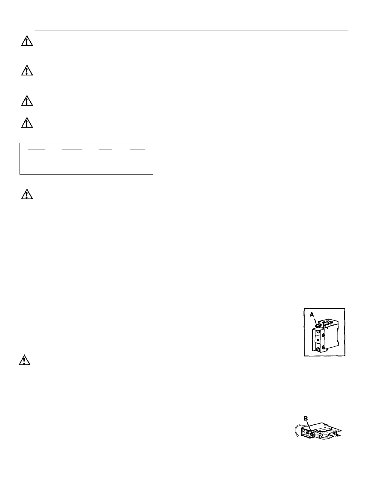
THERMOSTAT ADJUSTMENT
The thermostat is factory calibrated to produce 185°-190°F. (85°-88°C) water temperatures. If adjustment is necessary, turn
screw "A" clockwise to raise the set point.
NOTE: One-sixth of a turn equals 12°F.
(6.7"C). Thermostat adjustment screw
located at center of lower right side panel
when facing front of Hatco unit.
EGO-HIGH LIMIT ADJUSTMENT
If the water temperature in the heater exceeds 210°F.
(99°C), the high temperature limit will shut off the power.
The switch must be manually reset by pushing the red
button.
NOTE: If adjustment is necessary,
turn adjustment screw "B" clockwise to raise set point - 1/8 turn
equals about 7° F. (4°C). High
limit is located behind the front panel on the Hatco unit.
Page 3

REPLACEMENT PARTS LIST Model FR-5C
* Export Applications only.
≅ Part of Assembly.
Α Not shown.
Item Description Part No. Qty. Item Description Part No. Qty.
1 Tank 12A Power Relay - 900 DPST
2 Element Style 01.04.002C.00 1
*3 Element Style 01.04.004.00 1 12B *3 Pole Contactor-30A
2 Heating Element (220/380V units) 02.01.013.00 1
208 Volt-750/1625W R02.06.228.00 2 13 Control Relay 25A SPOT R02.01.025.00 1
240 Volt-750/1625W R02.06.229.00 2 14 "Power On" Yellow Pilot Light 02.19.152.00 1
*220/380 Volt -750/1625W R02.06.229.00 3 15 "Water At Temp" Green Pilot Light 02.19.150.00 1
3 Element Mounting Screw 16 Water Solenoid Value 03.02.026.00 1
(4 per Element) 05.04.062.00 8-12 17 Cleaning Hose w/Adapter 05.06.010.00 1
4 Element, Gasket (1 per Element) 05.06.005.00 2-3 18 Rubber Drain Stopper 05.06.026.00 1
5 Probe (for LWCO) 02.40.001.00 1 19 Cleaning Instruction Decal 07.03.250.00 1
6 Mushroom/Button Probe(for LWCO) 02.01.122.00 1 20 Sink Strainer Assembly (Complete R05.30.009.00 2
7 LWCO (Board Style) 02.01.121.00 1 21
8A Power-On/Off Switch (208/240V) 02.19.008A.00 1 22
8B Power On/Off Switch (220/380V) 02.19.016.00 1 23
9 High Temperature Limit Control 02.16.025A.00 1 24
10 Control Thermostat 02.16.003B.00 1 25
11 Sump Drain Handle 03.02.001B.00 1 26
(208/240V units) 02.01.008.00 1
Locknut≅
Gasket Kit (For both strainers Α
Thin Rubber Washer≅
Thick Neoprene Washer≅
Fiber Washer≅
Union Gasket≅
NOTE: Line strainers, filters, back flow preventers
and/or vacuum breakers to be supplied by
customer to meet state & local codes.
05.30.009A.00 2
R00.05.002.00 1
05.30.009C.00 2
05.30.009B.00 4
05.30.009A.00 2
05.06.009.00 2
Page 4

 Loading...