

Page 1
HYDRO-HEATER
Food Rethermalizers/Hot Food Table Heater
FFR2 Series
Installation & Operating Manual &
Replacement Parts List
I&W #07.05.125.00
This manual contains important safety information
concerning the maintenance, use and operation
of this product. Failure to follow the instructions
contained in this manual may result in serious injury.
If you are unable to understand the contents of this
manual, please bring it to the attention of your
supervisor. Do not operate this equipment unless
you have read and understood the contents of
this manual.
Este manual contiene importante información sobre
seguridad concerniente al mantenimiento, uso
y operación de este producto. Cualquier falla en
el seguimiento de las instrucciones contenidas en
este manual puede resultar en un serio daño. Si usted
no puede entender el contenido de este manual por
favor pregunte a su supervisor. No opere este equipo
al menos que haya leído y comprendido el contenido
de este manual.
Page 2
i
INTRODUCTION
Falcon FFR2 Hydro-Heater Food Rethermalizers/Hot
Food Table Heaters are designed to supply temperaturecontrolled water to a holding vessel (sink or tank)
located above the heater. Water flows by natural
convection from the holding vessel directly into
a tubular water chamber with heating elements uniquely
wrapped on the outside of the flow tube. The heating
elements do not come in direct contact with the water
eliminating sediment and lime buildup on the element,
resulting in longer life. The heated water flows upward
and returns to the holding vessel. A special electronic
controller maintains the setpoint temperature assuring
a responsive and efficient operation.
The unit electrical and plumbing connections
are factory-assembled and ready for installation.
This manual provides the installation, safety
and operating instructions for the Hydro-Heater Food
Rethermalizers/Hot Food Table Heaters. We recommend
all installation, operating and safety instructions
appearing in this manual be read prior to installation
or operation of your Falcon Hydro-Heater. Safety
instructions that appear in this manual after a warning
symbol and the words WARNING or CAUTION
printed in bold face are very important.
WARNING means there is the possibility of serious
injury or death to yourself or others. CAUTION
means there is the possibility of minor or moderate
injury. CAUTION without the symbol signifies the
possibility of equipment or property damage only.
Falcon Hydro-Heaters are a product of extensive
research and field testing. The materials used were
selected for maximum durability, attractive appearance
and optimum performance. Every unit is thoroughly
inspected and tested prior to shipment.
CONTENTS
Important Owner Information.....................................i
Introduction ...................................................................i
Important Safety Instructions .....................................1
Model Descriptions .......................................................2
All Models ..............................................................2
FFR2 Models ..........................................................2
Units with Built-In Temperature Control................2
Units with Remote Temperature Control................2
Specifications.................................................................3
Electrical Rating Chart - FFR2 Models..................3
Sizing Information ..................................................4
Dimensions..............................................................4
Electrical .................................................................4
Installation.....................................................................5
Plumbing .................................................................5
Auto-Fill..................................................................6
Operation.......................................................................7
Start-Up Procedures ................................................7
Minutes to Heat Table.............................................8
Maintenance ..................................................................9
General ....................................................................9
Daily........................................................................9
Weekly...................................................................10
Deliming Instructions............................................10
Replacement Parts List ..............................................11
IMPORTANT OWNER INFORMATION
Record the model number, serial number (identification
plate located on the lower right hand side, front corner
of the unit), voltage and purchase date of your
Hydro-Heater in the spaces below. Please have this
information available when calling Falcon for service
assistance.
Model No. ____________________________________
Serial No. ____________________________________
Voltage ______________________________________
Date of Purchase ______________________________
Contact the Hatco Corporation for Service Assistance,
Replacement Parts and Warranty Information.
Phone: (800) 558-0607; (414) 671-6350
Fax: (800) 690-2966; (414) 671-3976
Additional information can be found by visiting our
web site at www.hatcocorp.com.
Form No. FFR2M-1103
Page 3
CAUTIONS
Water in the unit and holding vessel is very hot.
Wear protective gloves and proper attire when
operating to avoid injury.
Do not use extension pipes on the inlet and outlet
connections on heater units. Poor performance
or unsafe conditions may occur.
CAUTIONS
Do not overtighten unions or nuts. Overtightening
may cause leaks.
Do not turn the electrical current to the unit
on until the holding vessel has been filled with
water or element burnout may occur.
Inspect weekly for lime buildup inside unit.
Excessive amounts can affect unit performance
and reduce the operating life of the unit.
To avoid any damage to the heater unit
use only delimers that are non-corr
osive
to aluminum, brass and stainless steel. Damage
caused by corrosive material or solutions
is not covered under warranty.
Drain holding vessel with power to the unit off,
or element burnout may occur.
Water Quality Requirements - Incoming water
in excess of 3.0 grains of hardness per gallon
(GPG) (.75 grains of hardness per liter) must
be treated or softened before being supplied
to a Hydro-Heater. Water containing over
3.0 GPG (.75 GPL) will decrease the efficiency
and reduce the operating life of the unit.
IMPORTANT SAFETY INSTRUCTIONS
1
WARNINGS
Falcon FFR2 series units are designed
for commercial use only by properly trained
personnel!
To avoid any injury, turn the power switch
off at the fuse disconnect switch/circuit breaker
or unplug the unit from the power source
and allow to cool completely before performing
any maintenance or cleaning.
For proper electrical installation conforming
to local electrical codes, consult a licensed
electrical contractor.
Units are designed to heat water up to 190ºF
(88ºC). DO NOT set temperature controls
to a setting higher than 190ºF (88ºC).
For proper plumbing installation conforming
to local plumbing codes consult a licensed
plumbing contractor.
If service is required on this unit, contact your
Authorized Falcon Service Agent, or contact
the Falcon Service Department at 513-752-1894;
fax 513-752-1891.
This product has no “user” serviceable parts. To
avoid damage to the unit or injury to personnel,
use only Authorized Falcon Service Agents and
Genuine Falcon Parts when service is required.
Genuine Falcon Replacement Parts are specified
to operate safely in the environments in which
they are used. Some aftermarket or generic
replacement parts do not have the characteristics
that will allow them to operate safely in
Falcon equipment. It is essential to use
Falcon Replacement Parts when repairing Falcon
equipment. Failure to use Falcon Replacement
Parts may subject operators of the equipment
to hazardous electrical voltage, resulting
in electrical shock or burn.
Form No. Form No. FFR2M-1103
IMPORTANT! Read the following important safety instructions to avoid personal injury or death,
and to avoid damage to the equipment or property.
Page 4
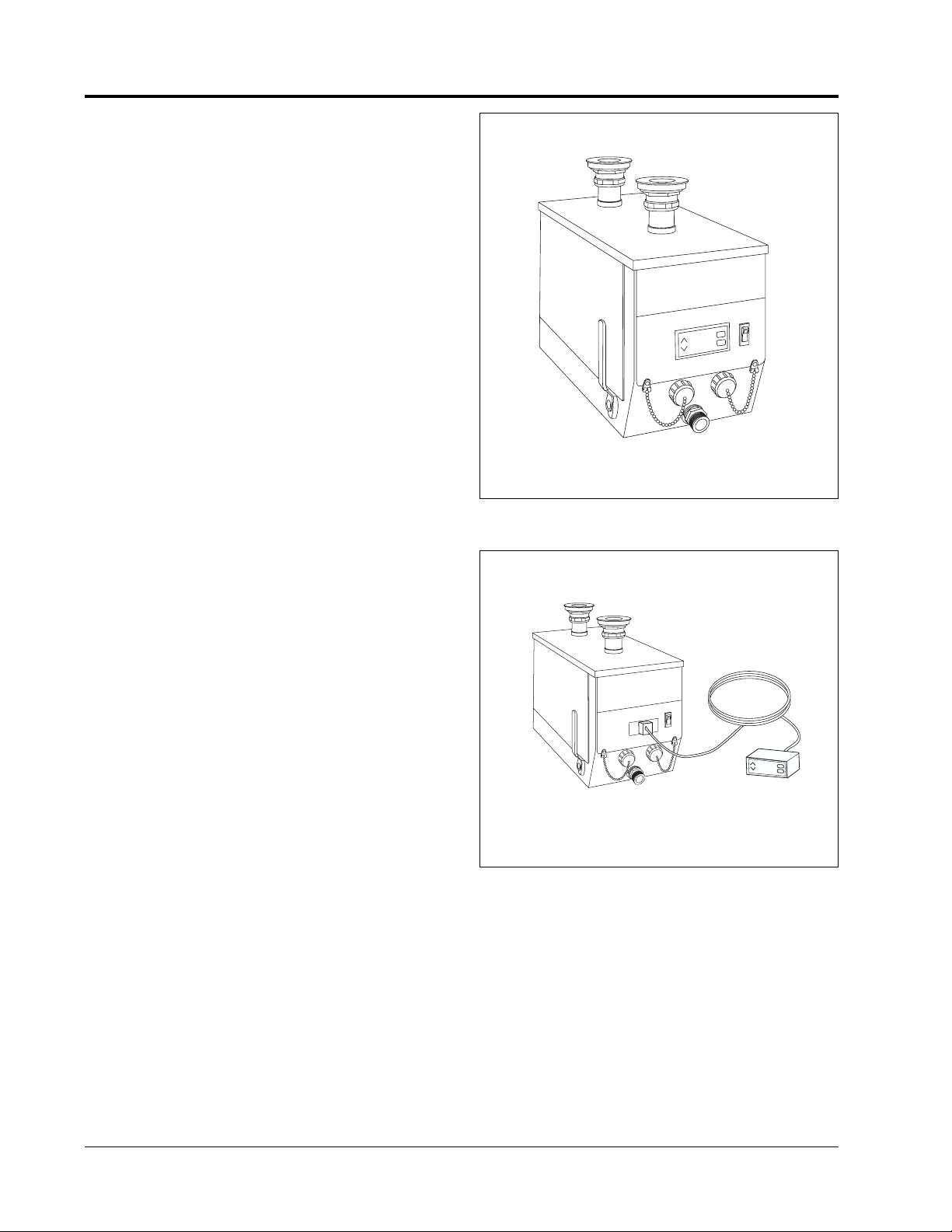
MODEL DESCRIPTIONS
2
ALL MODELS
The Hydro-Heater mounts easily to the underside
of a holding vessel, leaving the entire vessel area free.
Units are shipped ready to install with all gaskets
and fittings. Hydro-Heaters include a stainless steel
front, powder coated body, a low-water cut-off system
and a convenient drain outlet.
FFR2 MODELS
The Falcon FFR2 model heaters are designed
to be used with a Bain-Marie or Food Rethermalizer
to heat or hold foods at temperatures between 140ºF
(60ºC) and 190ºF (88ºC). The desired holding
temperature is maintained by a special electronic
controller and “free flow”technology.
UNITS WITH BUILT-IN TEMPERATURE
CONTROL
Units with built-in electronic temperature controller
and display are excellent for installations where the unit
is easily accessible and viewing is not obstructed.
UNITS WITH REMOTE TEMPERATURE
CONTROL
Units supplied with remote electronic temperature
controller and display allow for easy operator
monitoring and temperature control.
Figure 1. Hydro-Heater
with Built-In Temperature Controller
Figure 2. Hydro-Heater
with Remote Electronic Controller
Form No.
Form No. FFR2M-1103
Page 5

SPECIFICATIONS
3
Form No. Form No. FFR2M-1103
Kilowatts Wire Sizing Fuse or
Model Voltage (kW) Phase Amps AWG
*
†
Circuit Breaker
*
Shipping Weight
FFR2-3 208 3 1 14.5 14 20 24 lbs. (11 kg)
240 3 1 12.5 14 20 24 lbs. (11 kg)
FFR2-4 208 4 1 19.2 12 30 24 lbs. (11 kg)
240 4 1 16.7 12 30 24 lbs. (11 kg)
FFR2-6 208 6 3 16.7 12 30 27 lbs. (12 kg)
240 6 3 14.5 14 20 27 lbs. (12 kg)
FFR2-9 208 9 3 25.0 10 40 27 lbs. (12 kg)
240 9 3 21.7 10 30 27 lbs. (12 kg)
ELECTRICAL RATING CHART – FFR2 MODELS
NOTE: Models with “A” suffix equipped with auto-fill. Models with “R” suffix equipped with remote temperature
control. Models with “AR” suffix equipped with auto-fill and remote temperature control.
*
Based upon NEC 2002 Code
†
Based upon THHN wire rated 90ºC.
Page 6

SPECIFICATIONS
DIMENSIONS
A
C
B
ELECTRICAL
Install a fused disconnect switch or circuit breaker sized
according to the applicable Electrical Rating Chart.
The wiring from the switch or circuit breaker to the
Falcon unit must be in accordance with local electrical
requirements and codes.
WARNING
For proper electrical installation conforming
to local electrical codes, consult a licensed
electrical contractor.
Models come complete with all electrical wiring
and are equipped with three electrical knockouts, one
at the rear and one on each side towards the rear. When
performing installation, run electrical connections
through one of these knockouts.
NOTE: FFR2 Series units equipped with auto-fill have
two electrical knockouts; one at the rear and one
on the right, when facing control side.
NOTE: FFR2 Series units with remote electronic
controller require that the controller with 8 terminal
plug be connected to the 8 terminal receptacle located
on the front of the heater unit. Before mounting
controller, make sure it is located close enough
to the heater so the lead wires can be
properly connected.
4
Form No.
Form No. FFR2M-1103
Width (A) Depth (B) Height (C)
8-1/2" 17-1/8" 12-3/4"
(216 mm) (435 mm) (324 mm)
Figure 2. Dimensions
SIZING INFORMATION
Falcon recommends the following guidelines be used
to ensure proper operation and sanitation.
For FFR2 Series in a Bain-Marie or Steam Table
Application
• Minimum 750 watts (.75 kW) per square foot
(0.8 watts per sq. cm) of vessel top.
For FFR2 Series in a Food Rethermalizer
Application
• Minimum 2000 watts per square foot
(2.2 watts per sq. cm) of vessel top.
NOTE: Use the FFR2 unit for a vessel up to 6'
(1829 mm) long. Over 6' (1829 mm) minimum
two units required.
See the Minutes To Heat Table to determine the amount
of time required to heat water using a FFR2 series
in a Bain-Marie or Steam Table application.
Page 7

INSTALLATION
5
Form No. Form No. FFR2M-1103
PLUMBING
An adhesive backed paper template is shipped with
the unit and is used to locate the sink strainer holes.
Use the following procedure to install the heater unit
to the holding vessel.
NOTE: The FFR2 heater should be positioned with
no more than 3' (914 mm) on either side when mounted
under holding vessel. See Figure 4. A perforated water
baffle (not supplied with unit) must be used to distribute
the heated water properly.
NOTE: Use one FFR2 for a Hot Food Table
up to 6' (1829 mm) long. Over 6' (1829 mm) minimum
2 units required.
CAUTION
Do not use extension pipes on the inlet and outlet
connections on heater units. Poor performance
or unsafe conditions may occur.
1. Expose the adhesive back of the paper template
and stick the template on the bottom of the holding
vessel. Center the template with the words “Front
Cover” positioned against the front inside wall
of the vessel.
2. Center punch and drill a 3/4" (19 mm) pilot hole
at each of the two center marks on the template.
3. Remove the template and cut a 2" (51 mm) diameter
hole at each pilot hole location using a standard
#ATV1756 Greenlee cutter.
NOTE: If a #ATV1756 Greenlee cutter is not available,
use a standard Greenlee 1-1/2" conduit cutter
#500-6978, which is slightly under 2" (51 mm) diameter.
File or ream holes as necessary to 2" (51 mm) diameter
required for mounting sink strainers.
4. See Figure 5. In each of the holes, install a male
threaded sink strainer with a thin gasket between
the strainer flange and the bottom of the holding
vessel.
5. Install two thick gaskets at the underside
of the holding vessel along with a thin fiber gasket,
and secure finger tight with the nut.
6. Attach the heater to the strainers loosely with
the union nuts and 1-3/4" (45 mm) rubber gaskets.
NOTE: Make sure rubber gaskets are positioned inside
the union nuts and are not crimped.
3" (76 mm)
Thin rubber washer
Thick rubber
washers
(Qty. 2)
Thin fiber
washer
1/8" (3 mm)
offset
Sink or tank
Nut
Union nut
Union Gasket
Figure 5. Installing Sink Strainer
7. Tighten nuts on strainers securely.
8. Tighten union nuts securely.
9. Fill the holding vessel with water and check
for leaks.
CAUTION
Do not overtighten unions or nuts. Overtightening
may cause leaks.
NOTE: A 3/4" (19 mm) hose or pipe may be connected to the
heater sump drain and run to an open sight drain. The sump
drain should not be permanently connected to the sanitary
drain system. Check local plumbing code for proper drain
installation. See MAINTENANCE for more information.
Figure 4. Hydro-Heater Water Baffle
3'
3'
3/4" (19 mm) holes
around periphery on
6" (152 mm) centers
Dotted line
indicates the position of
perforated water baffle
3/4" (19 mm) high baffle
with divider wall between
inlet and outlet
(914 mm)
MAX
(
914 mm)
MAX
Page 8

INSTALLATION
6
Form No.
FFR2M-1103
CAUTION
Water Quality Requirements - Incoming water
in excess of 3.0 grains of hardness per gallon (GPG)
(.75 grains of hardness per liter) must be treated
or softened before being supplied to a
Hydro-Heater. Water containing over 3.0 GPG
(.75 GPL) will decrease the efficiency and reduce
the operating life of the unit.
AUTO-FILL
Units with the Auto-fill option require
the following
steps be completed before start-up.
WARNING
For proper plumbing installation conforming
to local plumbing codes consult a licensed
plumbing contractor.
1. Supply 1/4" NPT copper water supply line to inlet
of solenoid valve on heater.
NOTE: Ball valve or gate valve, line strainer, union(s)
and vacuum breaker or other anti-siphon device must
be supplied by table manufacturer or installer
if required.
2. Locate a point 2" (51 mm) up from the bottom
of the tank.
3. Mark and drill a 13/16" (21 mm) hole
into the sidewall of the tank.
4. Weld probe fitting (supplied) into sidewall of tank.
5. Install probe into tank using thread sealant.
6. Tighten until snug. Be careful not to overtighten nut.
Overtightening may cause leaks.
7. Turn on water and check for leaks.
8. Connect wire lead to probe.
Page 9

OPERATION
7
WARNINGS
Falcon FFR2 series units are designed for
commercial use only by properly trained personnel!
WARNINGS
Units are designed to heat water up to 190ºF (88ºC).
DO NOT set temperature controls to a setting higher
than 190ºF (88ºC).
CAUTION
Water in the unit and holding vessel is very hot.
Wear protective gloves and proper attire when
operating to avoid injury.
CAUTION
Do not turn the electrical current to the unit
on until the holding vessel has been filled with water
or element burnout may occur.
START-UP PROCEDURES
1. Make sure clean-out cap(s) (2-3 element units only)
are securely tightened. See Figure 6.
2. Close sump drain by moving handle all of the way
forward until it stops. See Figure 6.
3. Fill the holding vessel with hot tap water to normal
operating level.
4. Check that the fused disconnect switch or circuit
breaker is on, or if equipped with power cord
and plug make sure unit is plugged into proper
receptacle.
5. Turn power switch to ON position. The electronic
display will glow to indicate power is supplied.
6. To set the controller to the desired temperature press
“Set” button once; unit will display “SP1.”
See Figure 7.
7. Press “Set” button again; unit displays
current setpoint.
8. Press “Up” or “Down” arrow to change and display
desired setpoint.
9. Press “Set” button again until display goes blank.
After 5 seconds unit will display current operating
temperature.
NOTE: If steps 6-9 are interrupted or no changes
are made for 15 seconds the controller will go back
to its original setting without accepting the change.
Figure 7. Controller
Figure 6. Hydro-Heater Side View
Form No.
FFR2M-1103
SP1
Sump Drain Handle
(Closed)
Sump Drain Outlet
Power Switch
INLET
OUTLET
Clean-out Cap
(2- or 3-element
units only)
ADJUST
N
E
P
O
SP1
SET
Page 10

OPERATION
8
Water
Temp. At
Start-Up
Temperature °F (°C) Water Heated To:
Water
Temp. At
Start-Up
Temperature °F (°C) Water Heated To:
MINUTES TO HEAT TABLE
Form No. FFR2M-1103
9" (23 cm) DEEP WATER - 750 WATTS PER SQUARE FOOT OF VESSEL TOP
70 80 90 100 110 120 130 140 150 160 170 180
(21) (27) (32) (38) (43) (49) (54) (60) (66) (71) (77) (82)
60°F (16°C)
12 23 35 47 60 72 85 100 116 136 162 211
70°F (21°C) 12 24 36 49 61 74 89 105 125 151 200
80°F (27°C) 12 24 37 49 62 77 93 113 139 188
90°F (32°C) 12 25 34 50 65 85 101 127 176
100°F (38°C) 13 28 38 53 69 89 115 164
110°F (43°C) 12 25 40 56 66 102 151
120°F (48°C) 13 28 44 64 90 139
130°F (54°C) 15 31 51 77 126
140°F (60°C) 16 36 62 111
150°F (65°C) 20 46 95
160°F (71°C) 26 75
170°F (76°C) 49
6" (15 cm) DEEP WATER - 750 WATTS PER SQUARE FOOT OF VESSEL TOP
70 80 90 100 110 120 130 140 150 160 170 180
(21) (27) (32) (38) (43) (49) (54) (60) (66) (71) (77) (82)
60°F (16°C)
8 15 23 61 40 48 57 67 77 90 108 140
70°F (21°C) 8 16 24 33 40 49 59 70 83 100 133
80°F (27°C) 8 16 25334151 6275 92125
90°F (32°C) 8 17233343 5467 84117
100°F (38°C) 9 171535 4559 76109
110°F (43°C) 8 17 27 37 44 68 100
120°F (48°C) 9192942 6092
130°F (54°C) 10 21 34 51 84
140°F (60°C) 11 24 41 74
150°F (65°C) 13 31 63
160°F (71°C) 17 50
170°F (76°C) 33
Page 11

MAINTENANCE
9
GENERAL
WARNING
To avoid any injury, turn the power switch
off at the fuse disconnect switch/circuit breaker
or unplug the unit from the power source
and allow to cool completely before performing
any maintenance or cleaning.
Recommended Cleaning Schedule
Complete draining and cleaning should be done
• On a daily basis.
• Whenever food particles accumulate in the tank.
• Whenever a spill occurs.
• Whenever the unit is to be stored or shipped,
especially in freezing temperatures.
Helpful Hints
• Keep inlet and outlet free of debris.
• Keep false bottoms in place and free of debris.
• Delime unit using a non-corrosive deliming solution.
CAUTION
Inspect daily for lime buildup inside unit. Excessive
amounts can affect unit performance and reduce
the operating life of the unit.
DRAINING & CLEANING ALL MODELS
NOTE: The holding vessel should be drained through
its own drain valve to discharge debris and water that
remains in it.
CAUTION
Drain holding vessel with power to the unit off,
or element burnout may occur.
DAILY (See Figure 8)
1. Turn power switch to the OFF position.
2. Drain holding vessel to discharge visible water
and debris. Close drain when finished
3. Wipe visible deposits from the sink or tank.
4. Dissolve a safe, non-toxic, non-corrosive sanitizer
into 1 gallon (3.7 L) of hot water and pour into tank.
Refill the tank 1/2" (1 cm) above the false bottom
with hot water and soak for at least 15 minutes.
NOTE: Follow the sanitizers instructions for the proper
mixture of water and sanitizer.
5. Connect one end of a drain hose onto the sump drain
outlet with the other end in a bucket or open site
drain in a manner according to local plumbing codes.
6. To drain the unit open the sump drain valve by
moving the valve handle backwards until it
completely stops. Water will now flow from the
drain hose.
7. Thoroughly wash unit with fresh water until
discharge is clear and all sanitizers have been
removed and rinsed.
8. Close sump drain by moving handle all of the way
forward until it stops. See Figure 8.
9. Reinstall perforated water baffle/false bottom
in correct position.
10. Follow normal operation instructions.
Figure 8. Hydro-Heater Side View
Form No.
FFR2M-1103
Sump Drain Handle
(Closed)
Sump Drain Outlet
Power Switch
INLET
OUTLET
Clean-out Cap
(2- or 3-element
units only)
N
E
P
O
Page 12

WEEKLY (See Figure 8)
1. Turn power switch to the OFF position.
2. Drain holding vessel to discharge visible water
and debris.
3. Wipe visible deposits from the sink or tank.
4. Remove clean-out caps (2- or 3-element units only).
5. Inspect for lime and sediment build-up at the sump
drain outlet and heating element chamber outlets
(2 or 3 element units only have heating element
chamber outlets).
6. Remove any visible lime sediment or debris deposits
from the outlets using the cleaning brush supplied
with the unit, Falcon part number 03.40.060.00.
To remove, insert brush into the clean-out and sump
drain outlets and use a scrubbing motion until clean.
7. Remove brush and flush clean water through
the chambers until discharge is clear.
8. Reinstall clean-out caps removed in step 4.
9. Close all drains and fill with water before restarting.
DELIMING INSTRUCTIONS
CAUTION
Inspect weekly for lime buildup inside unit.
Excessive amounts can affect unit performance
and reduce the operating life of the unit.
NOTE: Product failure caused by liming or sediment
buildup is not covered under warranty.
CAUTION
To avoid any damage to the heater unit use only
delimers that are non-corr
osive to aluminum, brass
and stainless steel. Damage caused by corrosive
material or solutions is not covered under warranty.
The amount of lime and mineral content in the water
and how often the unit is operated will dictate how often
the unit needs to be delimed.
Units supplied with water that contains high lime and
mineral content may require deliming on a daily basis.
NOTE: The delimer used should be a safe, non-toxic,
non-corrosive solution. Follow the delimer’s
instructions.
In order to dissolve water scale, lime and rust deposits
from the heating chamber, thermostat probes and interior
surfaces of the unit, perform the following procedure:
MAINTENANCE
10
1. Disconnect power supply to heater at breaker
and turn power switch to OFF position.
2. Connect one end of a drain hose onto the sump
drain outlet with the other end in a bucket or open
site drain in a manner according to local
plumbing codes.
3. Open sump drain valve and drain all water.
4. When draining is finished, close sump drain valve.
5. Slowly add delimer and water mixture into heat tank
through sink strainer assemblies. Allow the unit
to stand with the mixture in the reservoir for the
recommended period of time.
NOTE: The time required will vary depending on the
solution used and amount of deposits in the reservoir.
6. After cleaning, drain all expended solution from
the unit through the sump drain.
7. Thoroughly wash heater tank with fresh water
for several minutes until discharge is clear and all
deliming solution has been removed and rinsed.
8. Close sump drain by moving handle all of the way
forward until it stops.
9. Follow normal operation instructions.
CAUTION
Do not turn the electrical current to the unit
on until the holding vessel has been filled with water
or element burnout may occur.
WARNING
If service is required on this unit, contact your
Authorized Falcon Service Agent, or contact
the Falcon Service Department at 513-752-1894;
fax 513-752-1891.
WARNING
This product has no “user” serviceable parts.
To avoid damage to the unit or injury to personnel,
use only Authorized Falcon Service Agents
and Genuine Falcon Parts when service is required.
WARNING
Genuine Falcon Replacement Parts are specified
to operate safely in the environments in which they
are used. Some aftermarket or generic replacement
parts do not have the characteristics that will allow
them to operate safely in Falcon equipment. It
is essential to use Falcon Replacement Parts when
repairing Falcon equipment. Failure to use Falcon
Replacement Parts may subject operators
of the equipment to hazardous electrical voltage,
resulting in electrical shock or burn.
Form No. FFR2M-1103
Page 13

REPLACEMENT PARTS LIST
11
Form No.
FFR2M-1103
FALCON FFR-2 Series
Food Rethermalizer/Bain Marie Heater
CAUTION - Use of replacement parts other
than those supplied by Falcon Corporation
may result in damage to the unit or injury
to personnel.
Model Designation
FFR2-XB
F = Falcon
F = Food
R = Rethermalizer
2 = 2nd Generation
X = Kilowatts
B = Balanced
Three-Phase
37
22
27
29
30
28
25
34
1
44
40
32
11
19
10
12
33
2
41
14
9
9
15
26
35
5
4
13
7
6
31
38
36
21
20
43
42
16
18
17
45
46
47
34
48
49
39
3
8
24
14
23
Page 14

12
Form No. FFR2M-1103
1 Temperature Probe 02.01.166.00 1
2 Probe, Low Water Cut Off 02.40.015.00 1
3 Ball Valve, Threaded 03.02.001.00 1
4 Ball Valve Handle 03.02.001B.00 1
5 Ball Valve, Hex Extension 03.02.029.00 1
6 Ball Valve, Stop Plate 03.02.030.00 1
7 3" (8 cm) Valve Extension 03.02.031.00 1
8 3/4" x 3/4" Brass Hex Nipple 03.05.057.00 1
9 O-Ring 03.40.059.00 2-6
10 Hose Clamp, S.S. 03.40.061.00 4
11 Inlet Hose 03.40.062F.00 1
12 Outlet Hose 03.40.062R.00 1
13 Rubber Gasket 05.06.006.00 1
14 Keps Nut 05.04.205.00 4
15 Rod, Threaded 05.04.419.00 2
16 Contactor - 3 Pole 02.01.167.00 1
17 Fuse, 2 Amp (2 per pack) R02.03.014.02 1
18 Fuse Block 02.03.022.00 1
19 Transformer, 208/240 - 24 Volt 02.17.046.00 1
20 On/Off Switch 02.19.081.00 1
21 Electronic Temperature
Controller 02.01.165R.00 1
22 Strainer Assembly with
Gaskets R05.30.009.00 2
23 Terminal Block - 3 Pole R02.15.035.00 1
24 Brass Hose Connector
with Shoulder 03.05.058.00 1
25 Cleaning Brush 03.40.060.00 1
26 Flush Hose Assembly 05.06.010.00 1
27 1-3/8" (4 cm) Rubber Stopper 05.06.026.00 1
28 Union Gasket 05.06.009.00 1
29 Strainer Gasket Kit! R00.05.0002.00 1
30 Brass Locknut 05.30.009A.00 2
31 Jacket, Black 04.06.220.00 1
32 Front Head Strap 04.06.223.00 2
33 Rear Head Strap 04.06.224.00 2
34 Side Panel, Black 04.06.222.00 2
35 Bottom Access Panel, Black 04.06.228.00 1
36 Front Control Panel 04.06.221.00 1
37 Top Assembly, S.S. 04.06.225.00 1
38 Drain Switch Kit R02.19.162.00 1
PARTS COMMON TO ALL FFR-2 MODELS
ITEM DESCRIPTION PART NO. QTY.
REPLACEMENT PARTS LIST
Note: S.S. is an abbreviation for stainless steel.
! Includes all gaskets for both strainers.
Page 15

PARTS SPECIFIC TO MODEL FFR2-3
ITEM DESCRIPTION
13
Form No. FFR2M-1103
REPLACEMENT PARTS LIST
240V with
Built-In
Electronic
Controller
240V with
Remote
Electronic
Controller
240V with
Built-In
Electronic
Controller
& Autofill
240V with
Remote
Electronic
Controller
& Autofill
208V with
Remote
Electronic
Controller
& Autofill
208V with
Remote
Electronic
Controller
208V with
Built-In
Electronic
Controller
208V with
Built-In
Electronic
Controller
& Autofill
R02.06.003F.00
03.17.001.00
03.17.002.00
---
---
---
02.01.212.00
---
---
---
---
HS1-5357
R02.06.003F.00
03.17.001.00
03.17.002.00
---
---
---
02.01.212.00
02.20.112.00
R02.18.133.00
---
---
10.01.043.00
R02.06.003F.00
03.17.001.00
03.17.002.00
---
---
---
02.01.121.00
---
---
02.40.001.00
03.02.033.00
10.01.044.00
R02.06.003F.00
03.17.001.00
03.17.002.00
---
---
---
02.01.121.00
02.20.112.00
R02.18.133.00
02.40.001.00
03.02.033.00
10.01.045.00
R02.06.001F.00
03.17.001.00
03.17.002.00
---
---
---
02.01.212.00
---
---
---
---
HS1-5357
R02.06.001F.00
03.17.001.00
03.17.002.00
---
---
---
02.01.212.00
02.20.112.00
R02.18.133.00
---
---
10.01.043.00
R02.06.001F.00
03.17.001.00
03.17.002.00
---
---
---
02.01.121.00
---
---
02.40.001.00
03.02.033.00
10.01.044.00
R02.06.001F.00
03.17.001.00
03.17.002.00
---
---
---
02.01.121.00
02.20.112.00
R02.18.133.00
02.40.001.00
03.02.033.00
10.01.045.00
39 Heating Element (Qty. 1)
40 Front Head
41 Rear Head
42 Cap, Clean Out
43 Gasket, Cap
44 Pipe, Clean Out
45 Low Water Cutt Off Board
46 8 Terminal Receptacle
47 Cable with Male Plug
48 Probe, Upper
49 Solenoid Valve
Electrical Diagram
PARTS SPECIFIC TO MODEL FFR2-4
ITEM DESCRIPTION
240V with
Built-In
Electronic
Controller
240V with
Remote
Electronic
Controller
240V with
Built-In
Electronic
Controller
& Autofill
240V with
Remote
Electronic
Controller
& Autofill
208V with
Remote
Electronic
Controller
& Autofill
208V with
Remote
Electronic
Controller
208V with
Built-In
Electronic
Controller
208V with
Built-In
Electronic
Controller
& Autofill
R02.06.004F.00
03.17.001.00
03.17.002.00
---
---
---
02.01.212.00
---
---
---
---
HS1-5357
R02.06.004F.00
03.17.001.00
03.17.002.00
---
---
---
02.01.212.00
02.20.112.00
R02.18.133.00
---
---
10.01.043.00
R02.06.004F.00
03.17.001.00
03.17.002.00
---
---
---
02.01.121.00
---
---
02.40.001.00
03.02.033.00
10.01.044.00
R02.06.004F.00
03.17.001.00
03.17.002.00
---
---
---
02.01.121.00
02.20.112.00
R02.18.133.00
02.40.001.00
03.02.033.00
10.01.045.00
R02.06.003F.00
03.17.001.00
03.17.002.00
---
---
---
02.01.212.00
---
---
---
---
HS1-5357
R02.06.003F.00
03.17.001.00
03.17.002.00
---
---
---
02.01.212.00
02.20.112.00
R02.18.133.00
---
---
10.01.043.00
R02.06.003F.00
03.17.001.00
03.17.002.00
---
---
---
02.01.121.00
---
---
02.40.001.00
03.02.033.00
10.01.044.00
R02.06.003F.00
03.17.001.00
03.17.002.00
---
---
---
02.01.121.00
02.20.112.00
R02.18.133.00
02.40.001.00
03.02.033.00
10.01.045.00
39 Heating Element (Qty. 1)
40 Front Head
41 Rear Head
42 Cap, Clean Out
43 Gasket, Cap
44 Pipe, Clean Out
45 Low Water Cutt Off Board
46 8 Terminal Receptacle
47 Cable with Male Plug
48 Probe, Upper
49 Solenoid Valve
Electrical Diagram
Page 16

14
Form No. FFR2M-1103
PARTS SPECIFIC TO MODEL FFR2-6
ITEM DESCRIPTION
240V with
Built-In
Electronic
Controller
240V with
Remote
Electronic
Controller
240V with
Built-In
Electronic
Controller
& Autofill
240V with
Remote
Electronic
Controller
& Autofill
208V with
Remote
Electronic
Controller
& Autofill
208V with
Remote
Electronic
Controller
208V with
Built-In
Electronic
Controller
208V with
Built-In
Electronic
Controller
& Autofill
R02.06.004F.00
03.17.003.00
03.17.004.00
03.40.063.00
05.06.066.00
03.11.013.00
02.01.212.00
---
---
---
---
HS1-5378
R02.06.004F.00
03.17.003.00
03.17.004.00
03.40.063.00
05.06.066.00
03.11.013.00
02.01.212.00
02.20.112.00
R02.18.133.00
---
---
10.01.046.00
R02.06.004F.00
03.17.003.00
03.17.004.00
03.40.063.00
05.06.066.00
03.11.013.00
02.01.121.00
---
---
02.40.001.00
03.02.033.00
10.01.047.00
R02.06.004F.00
03.17.003.00
03.17.004.00
03.40.063.00
05.06.066.00
03.11.013.00
02.01.121.00
02.20.112.00
R02.18.133.00
02.40.001.00
03.02.033.00
10.01.048.00
R02.06.003F.00
03.17.003.00
03.17.004.00
03.40.063.00
05.06.066.00
03.11.013.00
02.01.212.00
---
---
---
---
HS1-5378
R02.06.003F.00
03.17.003.00
03.17.004.00
03.40.063.00
05.06.066.00
03.11.013.00
02.01.212.00
02.20.112.00
R02.18.133.00
---
---
10.01.046.00
R02.06.003F.00
03.17.003.00
03.17.004.00
03.40.063.00
05.06.066.00
03.11.013.00
02.01.121.00
---
---
02.40.001.00
03.02.033.00
10.01.047.00
R02.06.003F.00
03.17.003.00
03.17.004.00
03.40.063.00
05.06.066.00
03.11.013.00
02.01.121.00
02.20.112.00
R02.18.133.00
02.40.001.00
03.02.033.00
10.01.048.00
39 Heating Element (Qty. 3)
40 Front Head
41 Rear Head
42 Cap, Clean Out
43 Gasket, Cap
44 Pipe, Clean Out
45 Low Water Cutt Off Board
46 8 Terminal Receptacle
47 Cable with Male Plug
48 Probe, Upper
49 Solenoid Valve
Electrical Diagram
PARTS SPECIFIC TO MODEL FFR2-9
ITEM DESCRIPTION
240V with
Built-In
Electronic
Controller
240V with
Remote
Electronic
Controller
240V with
Built-In
Electronic
Controller
& Autofill
240V with
Remote
Electronic
Controller
& Autofill
208V with
Remote
Electronic
Controller
& Autofill
208V with
Remote
Electronic
Controller
208V with
Built-In
Electronic
Controller
208V with
Built-In
Electronic
Controller
& Autofill
R02.06.003F.00
03.17.003.00
03.17.004.00
03.40.063.00
05.06.066.00
03.11.013.00
02.01.212.00
---
---
---
---
HS1-5379
R02.06.003F.00
03.17.003.00
03.17.004.00
03.40.063.00
05.06.066.00
03.11.013.00
02.01.212.00
02.20.112.00
R02.18.133.00
---
---
10.01.049.00
R02.06.003F.00
03.17.003.00
03.17.004.00
03.40.063.00
05.06.066.00
03.11.013.00
02.01.121.00
---
---
02.40.001.00
03.02.033.00
10.01.050.00
R02.06.003F.00
03.17.003.00
03.17.004.00
03.40.063.00
05.06.066.00
03.11.013.00
02.01.121.00
02.20.112.00
R02.18.133.00
02.40.001.00
03.02.033.00
10.01.051.00
R02.06.001F.00
03.17.003.00
03.17.004.00
03.40.063.00
05.06.066.00
03.11.013.00
02.01.212.00
---
---
---
---
HS1-5379
R02.06.001F.00
03.17.003.00
03.17.004.00
03.40.063.00
05.06.066.00
03.11.013.00
02.01.212.00
02.20.112.00
R02.18.133.00
---
---
10.01.049.00
R02.06.001F.00
03.17.003.00
03.17.004.00
03.40.063.00
05.06.066.00
03.11.013.00
02.01.121.00
---
---
02.40.001.00
03.02.033.00
10.01.050.00
R02.06.001F.00
03.17.003.00
03.17.004.00
03.40.063.00
05.06.066.00
03.11.013.00
02.01.121.00
02.20.112.00
R02.18.133.00
02.40.001.00
03.02.033.00
10.01.051.00
39 Heating Element (Qty. 3)
40 Front Head
41 Rear Head
42 Cap, Clean Out
43 Gasket, Cap
44 Pipe, Clean Out
45 Low Water Cutt Off Board
46 8 Terminal Receptacle
47 Cable with Male Plug
48 Probe, Upper
49 Solenoid Valve
Electrical Diagram
REPLACEMENT PARTS LIST
 Loading...