

Hastings POWERPOD 400 User Manual
Pod
TELEDYNE
HASTINGS
INSTRUMENTS
INSTRUCTION MANUAL
Power
Power Supply/Totalizer
400

Page
2
of 42
Manual Print History
The print history shown below lists the printing dates of all revisions and addenda created for this manual.
The revision level letter increases alphabetically as the manual undergoes subsequent updates. Addenda,
which are released between revisions, contain important change information that the user should incorporate
immediately into the manual. Addenda are numbered sequentially. When a new revision is created, all
addenda associated with the previous revision of the manual are incorporated into the new revision of the
manual. Each new revision includes a revised copy of this print history page.
Revision A (Document Number 164- 012005).................................................................................. January 2005
Revision B (Document Number 164-022005 ................................................................ ................ February 2005
Revision C (Document Number 164-062005 ............................................................................. .......... June 2005
Revision D (Document Number 164-082005 ................................................................................... August 2005
Revision E (Document Number 164-102005 ............................................................... ................... October 2005
Revision F (Document Number 164-012006)................................................................................... January 2006
Revision G (Document Number 164-092006 )……………………………………………………… September 2006
Revision G (Document Number 164-112006)……………………………………………………… November 2006
Visit www.teledyne-hi.com for WEEE disposal guidance.
Hastings Instruments reserves the right to change or modify the design of its equipment
without any obligation to provide notification of change or intent to change.

Page
3
of 42
Table of Contents
1.0 QUICK START INSTRUCTIONS................................................................................... 5
2.0 SAFETY.................................................................................................................. 6
3.0 FEATURES.............................................................................................................. 7
4.0 SPECIFICATIONS..................................................................................................... 9
5.0 FRONT PANEL ...................................................................................................... 10
6.0 REAR PANEL ......................................................................................................... 11
7.0 WIRING................................................................................................................ 12
7.1. POWER.........................................................................................................................................12
7.2. COMMUNICATIONS...................................................................................................................12
7.3. TRANSDUCER CONNECTIONS .................................................................................................13
7.4. ALARMS.......................................................................................................................................13
7.5. ANALOG SIGNAL FOLLOWERS .................................................................................................14
8.0 MANUAL OPERATION............................................................................................. 15
8.1. POWER ON/OFF ...........................................................................................................................15
8.2. CHANGING THE COMMAND SET POINT .................................................................................15
8.3. OVERRIDE OPEN.........................................................................................................................15
8.4. OVERRIDE CLOSED ....................................................................................................................15
8.5. SETTING A CHANNEL TO AUTO CONTROL............................................................................16
8.6. SETTING A CHANNEL TO DIRECTLY METER INCOMING SIGNALS.....................................16
8.7. SETTING A CHANNEL TO DISPLAY THE TOTALIZER FUNCTION........................................16
9.0 EXTERNAL/REMOTE OPERATION............................................................................. 18
9.1. SELECTING EXTERNAL/REMOTE OPERATION (FRONT PANEL ONLY)..................................... 18
9.2. CHOOSING RS-232 COMMUNICATION.....................................................................................18
9.3. CHOOSING RS-485 COMMUNICATION.....................................................................................18
10.0 SETUP/CAL MODE.................................................................................................. 19
10.1. ENTERING THE SETUP/CAL MODE .......................................................................................... 19
10.2. DISPLAY SETUP ..........................................................................................................................19
10.2.1. BLANKING A DISPLAY LINE/CHANNEL..............................................................................................19
10.2.2. SELECTING DISPLAY BRIGHTNESS....................................................................................................19
10.2.3. SELECTING UNIT-OF-MEASURE........................................................................................................20
10.2.4. SELECTING GAS ID......................................................................................................................... 20
10.2.5. SETTING A/D CONVERSION RATE (FILTER)......................................................................................20
10.2.6. FRONT PANEL LOCK OUT................................................................................................................21
10.3. TOTALIZER SETUP.....................................................................................................................21
10.3.1. COUNT UP TO A SET POINT............................................................................................................. 21
10.3.2. COUNT DOWN FROM A SET POINT ...................................................................................................22
10.3.3. COUNT CONTINUOUSLY.................................................................................................................. 22
10.4. EXTERNAL COMMUNICATION SETUP....................................................................................22
10.4.1. RS-232 SETTINGS...........................................................................................................................22
10.4.2. RS-485 SETTINGS...........................................................................................................................22
10.5. SELECTING THE ANALOG SIGNAL LEVEL ..............................................................................23
10.5.1. ZERO TO FIVE VOLT OPERATION...................................................................................................... 23

Page
4
of 42
10.5.2. ZERO TO TEN VOLT OPERATION......................................................................................................23
10.5.3. FOUR TO TWENTY MILLIAMP OPERATION........................................................................................23
10.6. SETTING LIMIT ALARMS...........................................................................................................24
10.6.1. SETTING A SINGLE CHANNEL’S HIGH LIMIT...................................................................................... 24
10.6.2. SETTING A SINGLE CHANNEL’S LOW LIMIT....................................................................................... 24
10.6.3. SETTING A SINGLE CHANNEL’S HYSTERESIS.....................................................................................24
10.7. SETTING RATIO CONTROL PARAMETERS ..............................................................................25
ENABLING RATIO CONTROL ........................................................................................................................25
10.8. CALIBRATING A CHANNEL TO ITS INCOMING SIGNALS......................................................26
10.8.1. RESETTING THE ZERO ONLY............................................................................................................ 26
10.8.2. RESETTING THE SPAN ONLY............................................................................................................ 26
10.8.3. RESETTING ZERO AND SPAN............................................................................................................27
10.8.4. SETTING A MULTIPLICATION FACTOR..............................................................................................27
10.9. SERIAL COMMUNICATION........................................................................................................28
10.9.1. COMMANDS....................................................................................................................................28
10.9.2. SET POINT QUERIES ........................................................................................................................28
10.9.3. ALARM/FLAG QUERIES ....................................................................................................................28
11.0 APPENDIX A.......................................................................................................... 30
12.0 APPENDIX B.......................................................................................................... 33
13.0 APPENDIX C......................................................................................................... 33
14.0 APPENDIX D......................................................................................................... 36
15.0 DRAWINGS........................................................................................................... 41
16.0 WARRANTY.......................................................................................................... 42
16.1. WARRANTY REPAIR POLICY.............................................................................................................42
16.2. NON-WARRANTY REPAIR POLICY.....................................................................................................42
Page
5
of 42
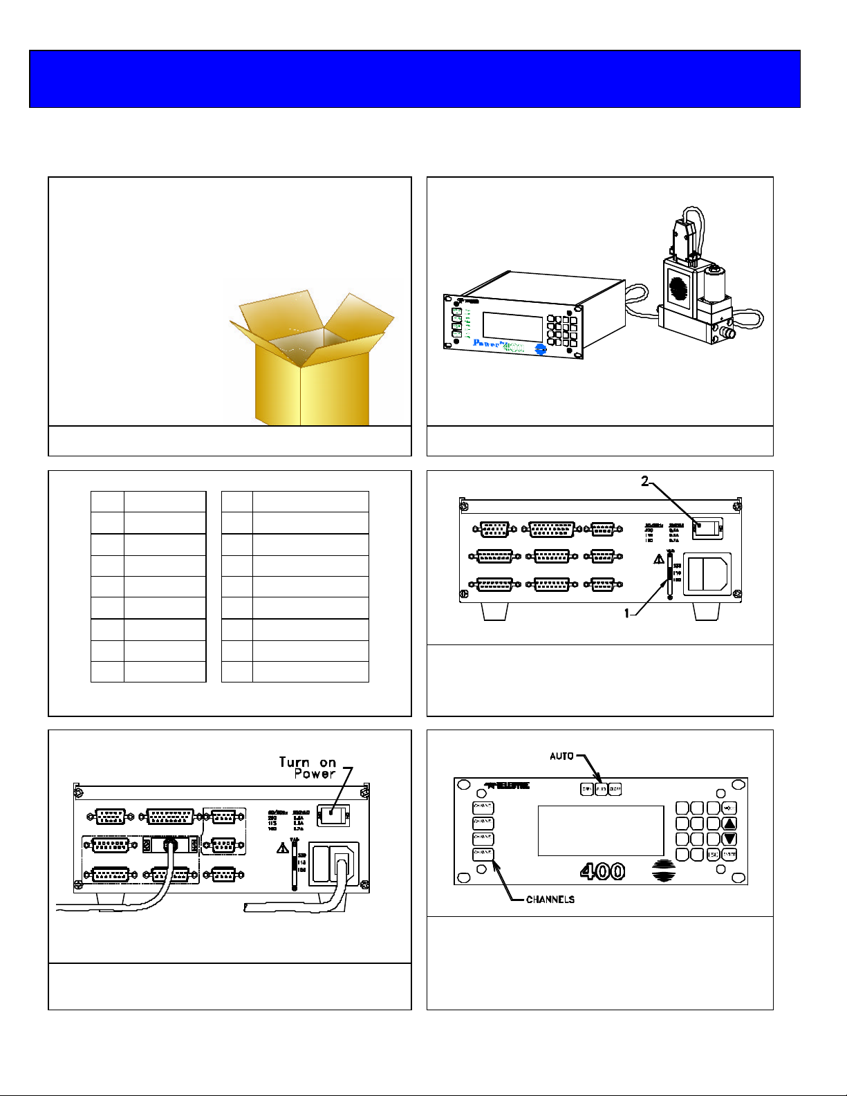
1.0 Quick Start Instructions
Important – The Power
Pod
-400 comes calibrated from the factory according to your specifications.
No set up is necessary unless you need to change the specs
1ea Power
1ea AC power cord
1ea 15-pin, Hi Density, D-style connector
1ea 9-pin, D-style connector
1ea user’s manual
When unpacking the Power
everything you need.
Pod
-400
Pod
, the package will contain
J-1 Ch1
J-2 Ch2
J-3 Ch3
J-4 Ch4
J-5 Analog out
J-6 RS-232
J-7 RS-485
J-8 Alarms
J-9 RS-485
5 Signal common
6 Analog signal
7 Case ground
8 Override Control
9 -15 VDC
10 NC
11 +15 VDC
12 Valve return
14 Set point (in)
Pin-outs
Connect a “known good” transducer to the desired
channel (See next frame for pin-outs)
1) Check power setting switch on the back panel
and make sure it is set appropriately.
2) Ensure the power switch is off, and then connect
the power cord.
Turn power switch to on position. If you have just
turned on the mass flow instrument and the power,
some settling is necessary.
OPEN
1
CLOSE
OPEN
2
CLOSE
OPEN
3
CLOSE
OPEN
4
CLOSE
1) Press the desired Channel # Key. Press the Auto
key.
1
4
7
0
HASTINGS
(For Controllers)
2) Press the desired Channel # Key. Enter desired
flow. Press the enter key.
3
2
6
5
9
8
.

Page
6
of 42
2.0 Safety
Read this manual in its entirety before operating the POWER
POWER
and meters. Read all wiring and power hookup instructions and understand the requirements prior to
using another manufacturer’s products with the POWER
interfaced with the POWER
standards before operating.
POD
-400 is designed to operate with most Teledyne Hastings Instruments (THI) flow controllers
POD
-400 is wired according to prevailing local safety and operational
POD
-400 Power Supply/Totalizer. The
POD
-400. Insure that any product being
The following symbols and terms may be found on THI products and/or in THI manuals and indicate
important information.
When found on the device, this symbol indicates that the operator should refer to
the manual for important instructions on the proper use of this device. When found
in the manual, this symbol indicates that the reader should understand the
implications contained in the text before operating the device.
This symbol indicates that a shock hazard may be present. Read the instruction
manual carefully and insure that the device is wired properly and that all settings
have been checked prior to applying power to the device.
The WARNING label indicates important information that should be heeded for safe and proper
performance of the device.
The label, CAUTION, is used to indicate that damage to the power supply or equipment
connected to it could occur if directions are not followed. Warranty could be invalidated if the
instructions in this manual are not followed.

Page
7
of 42
3.0 Features
The following com
mands are manual commands only:
The POWER
rack hardware or can be used as a bench top unit. The POWER
character, vacuum fluorescent display (VFD). The display emulates a liquid crystal display in its
command structure but the VFD gives the unit a greater viewing angle and better visibility than available
with most conventional LED or LCD displays. The display can be set to four different brightness levels.
Use a lower brightness setting to extend the already long expected life time of the display. Use brighter
settings for viewing areas where ambient light may be too bright or cause glare, or where greater viewing
distances are required.
Most features are accessible via the membrane keys on the front panel. Consult the section on each
function to check its availability. Operators are guided through the many features and options by selecting
their choices from an intuitive menu structure.
FRONT PANEL LOCKOUT
ANALOG RANGE SELECTION
Analog signal and control ranges are operator selectable. The operator can choose between three different
DC ranges:
POD
-400 serves as a convenient control center that can be rack-mounted using standard half-
POD
-400 is equipped with a 4 X 20
The Front Panel Lockout function is only available through serial communication. Manual
Overrides remain available during Lockout via a minimum number of keystrokes using
dedicated keys for this purpose and allow any command setting to be overridden in either the
high (open) or low (closed) state.
0 -5 VDC, 0-10 VDC or 4 -20 mA.
A fifteen (15) pin, high density, sub -miniature, D-type connector is provided for separate monitoring of
each channel’s analog transducer signal.
CAUTION: Consult the appropriate section for limits to the loading of these signals.
SERIAL COMMUNICATION
The POWERPOD-400 comes equipped with standard RS-232 and RS-485, serial communication. Most
functions, features, signals and alarms are accessible and modifiable via any remote computer.
OPEN, AUTO and CLOSE.
The status of these settings can be read via serial communication but they cannot be changed
except manually, from the front panel.

Page
8
of 42
POWER SELECTION
Power input is switchable between 100 VAC, 115 VAC and 230VAC (50
or 60 Hz) via
the rear panel. For the safety of the operator as well as the device, the correct power
level should be selected prior to connecting to the power mains. See the table
“POWERPOD-400 Specifications” in section 3.0 for the proper fusing when changing
power settings.
RATIO CONTROL
Ratio control is possible between channels using a familiar master/slave configuration. Channel one
(1) must be enabled as the master channel. Any combination of the remaining channels is possible
for slave channel assignment.
TOTALIZER
A Totalizer function is present for each channel with the capability of counting down from a set
point, counting up to a set point or continuous count up. The maximum count is ±999999 units.
When the set points are reached, a memory flag for each set point is set to a digital ‘1’ indicating a
Boolean ‘true’ value. The Totalizer set point flags must be polled via digital communication to be
read. Each flow channel has one low-limit and one high-limit set point available. These alarms are
available via open-collector, op to-isolated outputs on the rear panel as well as serial
communication.
POWER OUTAGES AND THE OVERRIDE CONDITION
In the event of a power outage, even one of short duration, the POWER
POD
-400 is
designed to conduct a software reset. During the period of time in which the reset is
occurring, it will not accept or respond to any commands either manually or digitally
until the reset process is completed. After said reset, the POWER
POD
-400 will have
remembered all previously entered set-points but all channels are designed to come up
in the “Override-CLOSEd” condition. For meters, this should have no affect on their
behavior. All analog -only, THI, flow controllers with normally-closed (NC) valves will
close and remain closed until operator intervention manually returns selected channels’
Override condition back to the AUTO mode.
For all other con trollers, this means that the control signal (pins 5 to 14) of J1 through
J4 will return to the previously set level. For controllers not taking advantage of the
Override function (pin 8), these controllers will return to their normal, preset operating
condition unless other intermediary steps are undertaken. Controllers that are making
use of the override function (Pin 8) and have normally-open valves will be driven to the
fully open condition.

Page
9
of 42
4.0 Specifications
Power
Specification Value Units Notes
Power Inputs
V
P 68 VA
f 50 -60 Hz
Transducer
Number Channels 4
V
I
I/O
Display
Type
# Lines 4
# Characters 20
Brightness Levels 4
A/D Converter
Filtering Rate 4, 15, 30,
Alarms
3 per channel 1 High
1 Low
1 Total
Dimensions
Front Panel (h x w) 3.5 x 9.5 in
Case (h x w x d) 3 x 8 x 9.5 in
Hole Centers (h x
w)
Weight 5 1/4 lbs
Supply
Supply
Pod
-400 Specifications Table
100
115
VAC
230
±15
±250
0 - 5
0 - 10
VDC Bi-polar
mA Bi-polar
VDC
4 - 20 mADC
100
Hz
3 x 8.825 in
0.7 A, 250VAC, SB Fuse
0.6 A, 250VAC, SB Fuse
0.315 A, 250VAC, SB Fuse
Vacuum Fluorescent,
LCD Emulator
Page
10
of 42
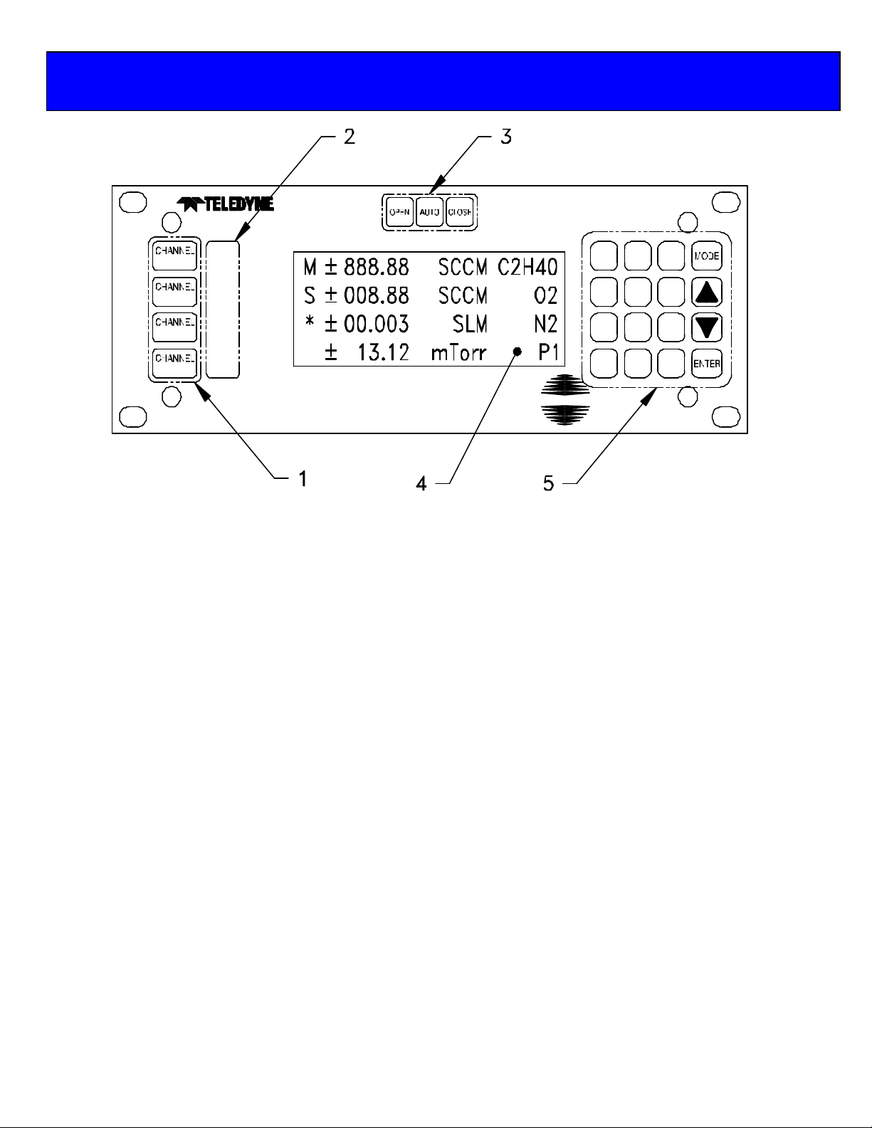
5.0 Front Panel
1. CHANNEL NUMBER SELECT KEYS
Selects channel for editing. An asterisk (*) appears in the first column of the display to indicate that this is the channel to
be edited.
2. OVERRIDE INDICATORS
Indicates when a channel’s command signal is overridden high (OPEN) or low (CLOSED).
3. OVERRIDE KEYS
Override the command signal on the ACTIVE CHANNEL. OPEN sets control override (pin 8) to +15V. CLOSED
sets command to –15V. AUTO allows the user to set the command signal for normal operation. A channel must be
active before these keys can become operational.
4. DISPLAY AREA
Column 1: Reserved for displaying ACTIVE CHANNEL (*), MASTER channel (M), SLAVE (S) or
Column 2: Reserved for polarity indicator.
Col’s 3 – 8: Signal monitor. Displays current input signal while in METER mode, AVERAGE while set
Column 9: Space
Col’s 10 – 14: UNITS OF MEASURE display.
Column 15: Space
Col’s 16 – 20: GAS ID.
5. KEYPAD
Use to enter SET POINTS or to modify the SETUP or CALIBRATION of control unit.
OPEN
1
CLOSE
OPEN
2
CLOSE
OPEN
3
CLOSE
OPEN
4
CLOSE
HASTINGS
1
4
7
0
3
2
6
5
9
8
.
400
TOTAL (T).
to average readings or TOTAL while in TOTALIZER mode.
Page
11
of 42
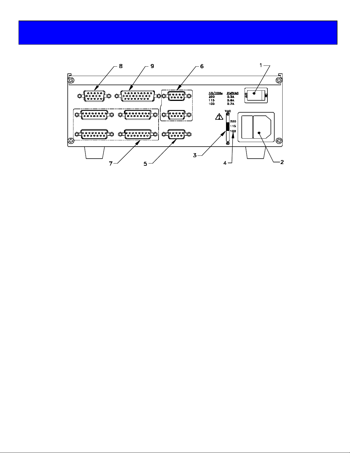
6.0 Rear Panel
1. POWER ON/OFF SWITCH
2. POWER INLET & FUSE
3. POWER SELECTOR SWITCH
4. FUSE Vs. POWER SETTING TABLE
5. RS-232 SERIAL PORT CONNECTOR (J6)
6. RS-485, DAISY CHAINED, SERIAL PORT CONNECTORS (J7, J9)
7. TRANSDUCER CONNECTORS (J1- J4)
8. ANALOG OUTPUT (J5)
9. ALARMS (J8)

Page
12
of 42
7.0 Wiring
J7, J9
1
Unused
Power
is
supplied through a fused,
AC jack on the rear panel
(item 2).Use the power cord
7.1. POWER
supplied with the unit (PN15-17-011 for 115 VAC, 60Hz). See the following table for
selecting the proper fuse rating. Use a metric, 5 x 20 mm sized, time-delayed fuse.
Power Setting (50 – 60 Hz) Fuse Rating THI P/N
100 VAC 0.315 Amp/250 VAC 23-05-038
115 VAC 0.60 Amp/250 VAC 23-05-039
230 VAC 0.70 Amp/250 VAC 23-05-040
Cords without plugs are supplied with units shipped outside of the U.S. Consult and comply with any
local laws and/or codes when connecting to any AC main. The AC input is user selectable between 100,
115 or 230 VAC, 50 or 60 Hz, via an AC selector switch next to the AC jack (Item 3).
WARNING: Be sure to set the power select switch prior to connecting to mains. Re-fuse the
connector according to the table above.
7.2. COMMUNICATIONS
Connectors J6 (Item 4), J7 (Item 6) and J9 (Item 6) are for RS-232, RS-485 connections respectively.
Settings for serial communication are accessible via the front panel.
J6 1 Unused
RS-232
(DB-9)
2 Tx
3 Rx
4 Unused
5 Gnd
6 Unused
7 RTS
8 CTS
9 Unused
RS-485
(DB-9)
2 Rx3 Tx+
4 Unused/Gnd (Gnd)
5 Unused
6 Gnd/VCC (VCC)
7 R+
8 T9 Unused

Page
13
of 42
J1, J2, J3, J4
1 NC
Connectors
15)
J8 1 Chnl 1, High Alarm
Isolated, High
Alarms
7.3. TRANSDUCER CONNECTIONS
Connectors J1, 2, 3 and 4 (Item 7) are 15 pin D style connectors wired in the standard Hastings
Instruments pin-out (H pin-out).
Transducer
(DB-
(H-Pinout)
2 NC Valve Cntrl
Voltage
3 NC mA Sig
4 NC mA Sig
5 Sig. Com.
6 Sig. In
7 Case Gnd.
8 Cntrl Over-ride 1.5mA
9 -15 VDC
10 NC
11 +15 VDC
12 Valve Return
13 NC Ext-In
14 Set Point Out
15 +5 VDC Ref. Not Used.
7.4. ALARMS
Connector J8 (item 9) provides the user with open-collector, opto-isolated alarms for individual channels.
Each channel is provided with one user settable “High” and one “Low” alarm.
Open
Collector,
Opto-
& Low
(HD DB-26)
2 Chnl 1, Low Alarm
3 Chnl 1, Alarm Return
4 Chnl 2, High Alarm
5 Chnl 2, Low Alarm
6 Chnl 2, Alarm Return
7 NC
8 NC
9 NC
10 NC
11 NC
12 NC
13 NC
14 NC
15 NC
16 NC
17 NC
18 NC
19 Chnl 3, High Alarm
20 Chnl 3, Low Alarm
21 Chnl 3, Alarm Return
22 Chnl 4, High Alarm
23 Chnl 4, Low Alarm
24 Chnl 4, Alarm Return
25 NC
26 NC
 Loading...