

Hastings DAVC-4, DAVC-6, DAVC-5 User Manual
TELEDYNE
HASTINGS
INSTRUMENTS
INSTRUCTION MANUAL
DIGITAL AVC
(DAVC-4, DAVC-5, DAVC-6)
ISO 9001
CERTIFIED

Manual Print History
The print history shown below lists the printing dates of all revisions and addenda created for this manual.
The revision level letter increases alphabetically as the manual undergoes subsequent updates. Addenda,
which are released between revisions, contain important change information that the user should incorporate
immediately into the manual. Addenda are numbered sequentially. When a new revision is created, all
addenda associated with the previous revision of the manual are incorporated into the new revision of the
manual. Each new revision includes a revised copy of this print history page.
Revision A (Document Number 174-062009).....................................................................June 2009
Revision B (Document Number 174-072009)......................................................................July 2009
Revision C (Document Number 174-072009) .....................................................................July 2009
Revision D (Document Number 174-062010) ....................................................................June 2010
Revision E (Document Number 174-082010)................................................................. August 2010
Visit www.teledyne-hi.com for WEEE disposal guidance.
Hastings Instruments reserves the right to change or modify the design of its equipment
without any obligation to provide notification of change or intent to change.
174-082010_Digital AVC Page 2 of 17

Table of Contents
1.0 GENERAL INFORMATION ............................................................................................................................ 4
1.1 FEATURES ....................................................................................................................................................... 4
1.2 SPECIFICATIONS ............................................................................................................................................. 4
1.3 COMPLIANCE DATA ........................................................................................................................................ 5
1.4 SAFETY ........................................................................................................................................................... 5
ACCESSORIES ............................................................................................................................................................... 5
2.0 INSTALLATION............................................................................................................................................... 7
2.1 POWER-I/O CABLE.......................................................................................................................................... 7
2.2 POWER REQUIREMENTS & PIN OUT............................................................................................................... 7
2.3 SERIAL COMMUNICATIONS PIN OUT ............................................................................................................. 7
2.4 ANALOG OUTPUT PIN OUT............................................................................................................................ 7
2.5 PRESSURE ALARMS PIN OUT.......................................................................................................................... 7
3.0 VACUUM GAUGE OPERATION.................................................................................................................... 9
3.1 QUICK START................................................................................................................................................. 9
3.2 ANALOG PRESSURE MEASUREMENT .............................................................................................................. 9
3.3 ALARM SET POINT........................................................................................................................................ 12
3.4 DIGITAL COMMUNICATIONS. ...................................................................................................................... 12
3.5 OPERATION AND PERFORMANCE ................................................................................................................. 14
3.6 GAUGE TUBE OPERATING PRINCIPLE.......................................................................................................... 15
3.7 CALIBRATION PROCEDURE .......................................................................................................................... 15
4.0 WARRANTY.................................................................................................................................................... 17
4.1 WARRANTY REPAIR POLICY......................................................................................................................... 17
4.2 NON-WARRANTY REPAIR POLICY................................................................................................................ 17
174-082010_Digital AVC Page 3 of 17

1.0 General Information
This manual contains technical and general information relating to the installation, operation, and
calibration of vacuum gauges and gauge tubes manufactured by Teledyne Hastings Instruments (THI).
For best performance, THI vacuum gauges should be operated with the appropriate THI gau ge tube.
Attempting to use a THI vacuum gauge with another manufacturer’s tubes may result in damage to both
the gauge and tube.
1.1 Features
The THI Digital AVC (DAVC), is a digital readout version of THI’s AVC vacuum gauge. The heated gauge
tube supplies an analog signal that is amplified for a zero to one volt signal out put. A precision A/D
converter, in conjunction with a microprocessor, measures the gauge tube’s signal output, converts the
measurement to a pressure reading using the gauge tube’s well defined output/pressure function, and then
provides the result to the end user through a serial communications port.
The DAVC is available for use with two of THI’s most popular gauge tube families: The DV-6 and DV-4.
The DV-6 range is 1.0 - 1000 mTorr. The DV-4 range is 0.2 - 20 Torr. All gauge-t ubes used with the Digital
AVC feature long life and minimal maintenance due to the use of rugged, noble-metal, thermocouple (TC)
gauge tubes that are designed specifically for each range.
1.2 Specifications
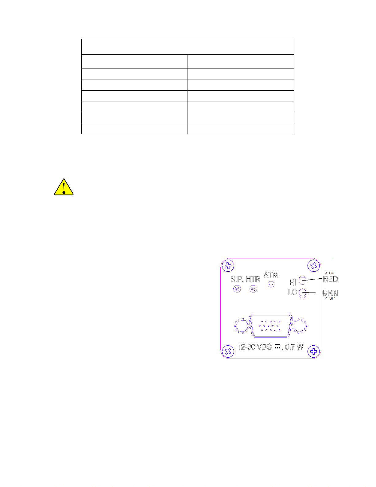
Input Power............................................................................................................................12 – 30 VDC
.................................................................................................................................................... 0.7 Watts
Cable.............................................................Combination power and RS232 cable, 1.5 meters, included
..................................................................... For CE Compliance, cable should never exceed 3.0 meters
Weight (Approx.) .......................................................................22 Oz’s (624 Grams) W/O Tube & Cable
Height (Length) .................................................................................................... 2.6”, W/O Tube & Cable
Width / Depth .................................................................................................................................... 1.75”
Operating temperature Range ............................................................................................ -20°C to 70°C
Standard Metal Gauge Tube.............................................................................. (DV-6R, DV-5M, DV-4R):
Overpressure (Gauge tubes) ................................................................................................. 50 psig max.
Material of Construction................................................................................... DAVC Housing: Aluminum
............................................................................................................Thermocouple: Glass, Noble Metal
Connections.........................................................................................High Density, 15-Pin, D Connector
.........................................................................................................Octal Tube Socket for Thermocouple
Alarms..............................................................................................................................0.50 Amps, max.
-8
Tube Leak Test.......................................................................................................<1x10
atm cc/sec He
See tube Product Bulletin for available tube connection configurations.
174-082010_Digital AVC Page 4 of 17
1.3 Compliance data
1.4 Safety
The following symbols and terms may be found on THI products and/or in THI manuals and indicate
important information.
The WARNING label indicates important information that should be heeded for safe and proper
performance of the device.
CE Standard Compliance
Test Standard
SAFETY EN61010
EMC/EMI Family EN61326
CONDUCTED/RADIATED EN55011
ESD EN61000-4-2
RF EN61000-4-3
CONDUCTED IMMUNITY EN61000-4-6
When found on the device, this symbol indicates that the operator should refer to the manual for
important instructions on the proper use of this device. When found in a manual, this symbol
indicates that the reader should understand the implications contained in the text before
operating the device.
The label, CAUTION, is used to indicate that damage to the power supply or equipment connected to it,
could occur if directions are not followed. Warranty could be invalidated if the instructions in this manual are
not followed.
Accessories
1.4.1 Installation Accessories
THI offers a complete line of system attachments that
permit easy maintenance for contaminated operations.
Gauge tubes are offered with various system fittings to
match almost any system requirement. Additionally,
THI’s complete line of quick disconnect attachments
allows customers to install these special fittings and
easily replace sensors without vacuum sealant or
Teflon® tape. For particularly dirty systems, Hastings
offers a particle dropout trap containing a series of nine
separate baffles which prevent solid contaminants from
having a direct path to the sensor’s thermopile.
1.4.2 DV-6S: New DV-6 tube For Severe
Environments
Hastings Instruments has developed a new gauge tube, the DV-6S, which is specifically designed for
outdoor use on cryogenic tanks including railcar and tanker truck applications. In addition to the DAVC, the
gauge tube is compatible with the hand-held HPM-4/6 and the analog VT-6.
The DV-6S is supplied with a protective cap. The o-ring-sealed cap protects the gauge tube pins from
moisture thus significantly reducing corrosion. A metal lanyard prevents cap loss. The tube is provided with
a standard 1/8” NPT fitting; however special fitting requests can often be met.
174-082010_Digital AVC Page 5 of 17

1.4.3 Calibration Reference
Tubes
THI Reference Tubes employ the
same metal thermopiles used in all
THI Vacuum Gauge Tubes. The
thermopile is sealed in a glass
capsule that has been evacuated,
baked, out-gassed, and then aged to
ensure long-term stability. The sealed
capsule is then housed in a protective
metal shell to provide a rugged,
trouble-free assembly.
Once assembled, the reference
gauge tube is accurately calibrated to
precisely simulate a gauge tube at a
given operating pressure. It provides
quick and easy instrument recalibration by merely plugging the
instrument and, in the case of the
DAVC, adjusting the HTR
potentiometer until the display reads
the exact pressure noted on the
reference tube.
Vacuum Gauge Tubes 1000 mTorr Range
Stock # Model # Description
55-38 DV-6M 1/8” NPT Standard (Yellow base)
55-38R DV-6R 1/8” Ruggedized
55-38RS DV-6 1/8” NPT Rohs Rugged
55-38S DV-6S 1/8” NPT Rugged/Vibration
55-251 DV-6-KF-16 KF-16TM
55-267 DV-6-KF-25 KF-25TM
55-283 DV-6-VCR VCRTM
55-38R-CF DV-6R-CF Mini ConflatTM
Extension Cables for VT Series (DAVC)
55-3 OM-8-OFV 8 Ft Extension Cable
55-22 OM-12-OFV 12 Ft Extension Cable
65-53 OM-25-OFV 25 Ft Extension Cable
65-102 OM-50-OFV 50 Ft Extension Cable
55-142 OM-100-OFV 100 Ft Extension Cable
Vacuum Gauge Tubes 20Torr Range
55-19 DV-4D 1/8” NPT (Purple Base)
55-19R DV-4R 1/8” NPT Ruggedized
55-258 DV-4D-KF-16 KF-16TM
55-266 DV-4D-KF-25 KF-25TM
55-227 DV-4D-VCR VCRTM
Vacuum Gauge Tubes 100 mTorr Range
55-19 DV-5M 1/8” NPT (Red Base)
55-230 DV-5M -VCR VCRTM
Reference Tubes for use with DAVC
55-104 DB-20 Ref Tube (DV-6) for DAVC-6 Calibration
55-101 DB-16D Ref Tube (DV-4D) for DAVC-4 Calibration
55-103 DB-18 Ref Tube (DV-5) for DAVC-5 Calibration
174-082010_Digital AVC Page 6 of 17
 Loading...