

Hasler WJ185, WJ220, WJ250 User Manual

1
ORIG0140-1
4127718F/B
02/26/2007
INTRODUCTION
Congratulations on choosing the Hasler WJ185/220/250 mailing
machine. The WJ185/220/250 is the result of the expertise and
innovative capabilities of a worldwide Hasler group and, using ink
jet technology, it will integrate into your working environment to
enhance your mail processing operation.
The WJ185/220/250 has many capabilities that will be important
to your business:
As well as being productive (up to 250 letters per minute for
machine only, and up to 125 letters per minute in dynamic scale
mode), the WJ185/220/250 is designed to be a user friendly
machine that can fit into any working environment with its innovative
and attractive design, simple user settings and very low noise
level. The high volume capacity and sealed ink system makes it
easy and safe to handle, and the user interface is particularly clear
with a graphic interface, pop up menus and 10 memories to store
favorite jobs.
The WJ185/220/250 is adaptable and as such can handle many
different types of mail. The optional feeder can be used to
process, in a continuous cycle, items of different sizes (ranging
from postcards to large flats in portrait format) and thick items (up
to 5/8 inch), with automatic imprint shift. For thicker mail items or
packages, adhesive labels can be automatically dispensed.
The WJ185/220/250 is connectable. It can exchange data with
Hasler scales printers and PC's in order to provide optimal mail
processing and reporting.
Finally, the WJ185/220/250 is a unique communication tool for
your company. Its high quality printing combined with its integrated
library of advertisement messages, mail class dies and free
format text will afford you extra tools to enhance your company’s
image and the impact of your mail.
You will very soon discover for yourself that the WJ185/220/250 is
the ultimate in quality and productivity for mail processing
equipment.

2
ORIG0140-2
4127718F/B
02/26/2007
WARNING!
Do not remove any secured covers or attempt to repair the WJ185/
220/250, there are no user serviceable parts contained and the
WJ185/220/250 product is licensed for use under the conditions of the
Post Office. This license is issued subject to the product being secure
at all times. Any removal of covers or dis-assembly of the product will
result in the license being revoked and may result in the Post Office
requesting Hasler to remove the product from use.
The inking system used within the WJ185/220/250 contains Post
Office approved ink. This cartridge should not be tampered with in any
way or the use of non approved inks be attempted. This will breach any
Post Office licence agreement on the product and may result in the
Post Office requesting Hasler to remove the product from use.
FCC COMPLIANCE STATEMENT
This equipment has been tested and found to comply with the limits
for a Class A digital device, pursuant to Part 15 of the FCC Rules.
These limits are designed to provide reasonable protection against
harmful interference when the equipment is operated in a commercial
environment. This equipment generates, uses, and can radiate radio
frequency energy and, if not installed and used in accordance with this
instruction manual, may cause harmful interferences to radio communications. Operation of this equipment in a residential area is likely
to cause harmful interference, in which case the user will be required
to correct the interferences at his own expense.
The internal modem of this equipment complies with Part 68 of the
FCC rules.
INSTALLATION
The power plug on this equipment is intended to serve as the device
for isolation of the electrical supply. The equipment should be installed
in close proximity to easily accessible electrical outlet and telephone
wall connector.
No part of this document may be reproduced or transmitted in any
form or by means, electronic or mechanical, for any purpose without
the express written permission of Hasler.
Copyright© Hasler 2004

3
ORIG0140-3
4127718F/B
02/26/2007
TABLE OF CONTENTS
GETTING STARTED .............................................9
SECTION A: BASIC FUNCTIONS ......................11
1. OVERALL PRESENTATION ................................................13
1.1 Overview ................................................................ 13
1.1.1 Overall view (mailing machine and optional
standard automatic feeder) ............................ 13
1.1.2 Overall inside view with optional standard
automatic feeder............................................ 14
1.1.3 Mixed-mail feeder (optional)........................... 15
1.1.4 T ouch screen and keyboard........................... 16
1.2 Installation ..............................................................18
1.2.1 Preparation of the mailing machine ................18
1.2.2 Installation with the feed platform .................... 18
1.2.3 Installation of the standard automatic feeder
(optional: available on WJ185 only) ................ 19
1.2.4 Installation of the mixed-mail feeder (optional) 20
1.2.5 Installation of the dynamic scale (optional) ...... 23
1.2.6 Connections at the rear of the units................. 25
1.2.7 Ink tank and printhead .................................... 28
1.2.8 Installation of the Weighing Platform ............... 31
1.3 Envelope feeding ................................................... 36
1.3.1 With the standard automatic feeder................ 36
1.3.2 With a mixed-mail feeder ............................... 38
1.3.3 With feed platform alone ................................41
1.4 Label feeding ......................................................... 42
1.5 Filling of the removable water bottle ........................ 43
1.5.1 Standard automatic feeder............................. 43
1.5.2 Mixed-mail feeder .......................................... 44

4
ORIG0140-4
4127718F/B
02/26/2007
1.6 Envelope moistening .............................................. 44
1.6.1 Standard automatic feeder............................. 44
1.6.2 Mixed-mail feeder .......................................... 45
1.7 Operation with an inserter ....................................... 48
2. PROTECTION BY AN ACCESS PIN CODE .......................50
3. USING A SCALE ...................................................................51
3.1 Using dynamic scale ..............................................53
3.1.1 Dynamic scale OFF mode ............................. 53
3.1.2 Dynamic scale ON mode ............................... 53
3.1.3 Dynamic scale batch mode ............................ 54
3.2 Operation with an external weighing platform .......... 54
3.2.1 WP standard mode........................................ 54
3.2.2 Differential Weighing Mode............................ 56
3.2.3 WP piece counting mode............................... 6 1
3.2.4 Manual weight entry mode..............................63
3.3 Country and insurance ............................................ 65
4. ENTERING POSTAGE VALUE AND MAIL PROCESSING 68
4.1 Entering postage value ........................................... 68
4.1.1 Manually......................................................... 6 8
4.1.2 With an external scale .................................... 68
4.1.3 With a dynamic scale ..................................... 68
4.2 Mail processing...................................................... 72
4.2.1 Envelopes with Autofeed Sealer (except batch
mode) ............................................................ 72
4.2.2 Envelopes with dynamic scale in batch mode. 72
4.2.3 With the feed platform alone........................... 73
4.2.4 Labels............................................................ 73
5. MODIFICATION OF THE IMPRINT .....................................74
6. USING DEPARTMENTS ......................................................76
7. OPERATION WITH AN EXTERNAL PC REMOTE
CONTROL ............................................................................77

5
ORIG0140-5
4127718F/B
02/26/2007
8. TELE-METER SETTING® CONNECTION ........................78
8.1 Adding Postage ..................................................... 78
8.2 Clearing a PO lockout ............................................ 79
8.3 Completing an interrupted add postage transaction 80
9. ONLINE SERVICES .............................................................80
10. OPERATION WITH A ROLL TAPE DISPENSER (RTD) ..... 81
10.1 Overview ................................................................ 81
10.2 Connections at the rear of the units ......................... 82
10.3 Loading label roll .................................................... 82
10.4 Using the RTD ........................................................ 84
10.5 Maintenance........................................................... 85
SECTION B: ADVANCED FUNCTIONS ............. 89
1. FURTHER FUNCTIONS ......................................................91
1.1 Mode...................................................................... 91
1.1.1 Pass through (seal only , no postage) mode .... 91
1.1.2 Dating mode.................................................. 92
1.2 Mailing machine general configuration.................... 92
1.3 Configuration of the main screen display ................93
2. JOB MEMORY SAVING .......................................................95
2.1 Storing in user memory "0" ..................................... 95
2.2 Recalling memories................................................ 95
3. REPORT PRINTING ............................................................97
3.1 Operating mode: .................................................... 97
3.2 Batch Registers.................................................... 100
3.3 Automatic Call List ............................................... 101
3.4 Active Feature List ............................................... 102
3.5 Modules Details ...................................................102
3.6 Activity Error List .................................................. 103
3.7 Activity History Report ..........................................105

6
ORIG0140-6
4127718F/B
02/26/2007
4. SUPERVISOR MODE ........................................................106
4.1 Enabling the supervisor mode .............................. 106
4.2 Automatic date advance ....................................... 110
4.3 User setup (in supervisor mode) ........................... 113
4.4 Supervisor setup .................................................. 113
4.4.1 Security........................................................ 114
4.4.2 Time ............................................................ 115
4.4.3 Timeout........................................................ 116
4.4.4 Load rate table............................................. 117
4.4.5 Dynamic Scale T ests.................................... 117
4.4.6 T ouchscreen calibration................................ 118
4.4.7 Serial port setup........................................... 119
4.5 Display setup ....................................................... 119
4.6 Departments ........................................................120
4.7 Printing inker servicing ......................................... 122
4.8 Reports ................................................................ 123
4.9 Ink information ...................................................... 125
4.10 Postal services..................................................... 125
4.10.1 Audit ............................................................ 128
4.10.2 Update registers .......................................... 129
4.11 Online services ..................................................... 129
4.12 Downloading an advertisement slogan or a mini die. 129
4.13 Rate configuration ................................................ 131
4.14 Dynamic scale high accuracy configuration mode. 131
4.15 Programming memories 1 to 9 ............................. 133
4.16 Text modification...................................................135
4.17 Exiting the supervisor mode.................................. 136

7
ORIG0140-7
4127718F/B
02/26/2007
SECTION C: MAINTENANCE ADVICE ........... 137
1. TROUBLE SHOOTING .....................................................139
1.1 Misfeed................................................................ 139
1.1.1 In the standard automatic feeder .................. 139
1.1.2 In the mixed-mail feeder ...............................139
1.1.3 In the mailing machine.................................. 139
1.1.4 In the dynamic scale ..................................... 141
1.2 Problems machine and feeder.............................. 142
1.3 Problems roll tape dispenser ................................ 145
1.4 Problem dynamic scale ........................................ 149
2. GENERAL MAINTENANCE ...............................................150
2.1 Replacement of the brush and moistening sponges150
2.2 Mixed-mail feeder................................................. 151
2.3 Cleaning of the rollers ........................................... 153
2.4 Cleaning the printhead.......................................... 154
2.5 Replacing the envelope pressure units (dynamic
scale) ...................................................................155
2.6 Removal of the postage meter .............................. 156
2.7 T ouchscreen precautions ...................................... 157
SECTION D: MAINTAINING YOUR TELE-
METER SETTING® ACCOUNT.................. 159
1. ACCOUNT NUMBER .........................................................161
2. ACCOUNT BALANCE ........................................................161
3. STATEMENTS ....................................................................161
4. POST OFFICE REGULATIONS ........................................162
5. POSTAGE NOW ................................................................. 162
6. STANDARD TMS® BANK ACCOUNTS............................163
7. WHERE TO MAIL YOUR DEPOSIT: ................................. 165

8
ORIG0140-8
4127718F/B
02/26/2007
INTERNATIONAL LETTER POST COUNTRY
CODE CHART .............................................. 167
SPECIFICATIONS ............................................ 169
ORDERING SUPPLIES ..................................... 1 72
CONTACT INFORMATION............................... 173
INDEX ................................................................ 174

Getting Started 9
ORIG0140-9
4127718F/B
02/26/2007
GETTING STARTED
1 Switch on the machine;
2 Enter your PIN number using the numeric keys and validate by
touching
OK
(see "Specifications" for initial access code);
3 Enter the postage print value using the numeric keys;
4 Place an envelope on the feed platform;
5 Press
START
STOP
.
Congratulations! You have succeeded in metering an envelope.
10
ORIG0140-10
4127718F/B
02/26/2007
Special icons
Signals an essential piece of information that cannot be
missed.
Signals an important issue.
Indicates an interesting idea or trick
Illustration through an example
According to the machine configuration, the menu lists
may change.

11
ORIG0140-11
4127718F/B
02/26/2007
SECTION A: BASIC FUNCTIONS
1. OVERALL PRESENT A TION .............................................13
1.1 Overview 13
1.1.1 Overall view (mailing machine and optional
standard automatic feeder) 13
1.1.2 Overall inside view with optional standard
automatic feeder 14
1.1.3 Mixed-mail feeder (optional) 15
1.1.4 T ouch screen and keyboard 16
1.2 Installation 18
1.2.1 Preparation of the mailing machine 18
1.2.2 Installation with the feed platform 18
1.2.3 Installation of the standard automatic feeder
(optional: available on WJ185 only) 19
1.2.4 Installation of the mixed-mail feeder
(optional) 20
1.2.5 Installation of the dynamic scale (optional) 23
1.2.6 Connections at the rear of the units 25
1.2.7 Ink tank and printhead 28
1.2.8 Installation of the Weighing Platform 31
1.3 Envelope feeding 36
1.3.1 With the standard automatic feeder 3 6
1.3.2 With a mixed-mail feeder 38
1.3.3 With feed platform alone 41
1.4 Label feeding 42
1.5 Filling of the removable water bottle 43
1.5.1 Standard automatic feeder 43
1.5.2 Mixed-mail feeder 44
1.6 Envelope moistening 44
1.6.1 Standard automatic feeder 44
1.6.2 Mixed-mail feeder 45
1.7 Operation with an inserter 48
2. PROTECTION BY AN ACCESS PIN CODE ......................50
3. USING A SCALE .............................................................. 51
3.1 Using dynamic scale 53
3.1.1 Dynamic scale OFF mode 5 3
3.1.2 Dynamic scale ON mode 53
3.1.3 Dynamic scale batch mode 54

12
ORIG0140-12
4127718F/B
02/26/2007
3.2 Operation with an external weighing platform 54
3.2.1 WP standard mode 54
3.2.2 Differential Weighing Mode 56
3.2.3 WP piece counting mode 61
3.2.4 Manual weight entry mode 6 3
3.3 Country and insurance 65
4. ENTERING POST AGE V ALUE AND MAIL PROCESSING 68
4.1 Entering postage value 6 8
4.1.1 Manually 68
4.1.2 With an external scale 68
4.1.3 With a dynamic scale 68
4.2 Mail processing 72
4.2.1 Envelopes with Autofeed Sealer
(except batch mode) 72
4.2.2 Envelopes with dynamic scale in batch
mode 72
4.2.3 With the feed platform alone 73
4.2.4 Labels 73
5. MODIFICA TION OF THE IMPRINT...................................74
6. USING DEP ARTMENTS ...................................................76
7. OPERA TION WITH AN EXTERNAL PC REMOTE
CONTROL ........................................................................ 77
8. TELE-METER SETTING® CONNECTION .........................78
8.1 Adding Postage 78
8.2 Clearing a PO lockout 79
8.3 Completing an interrupted add postage transaction 80
9. ONLINE SERVICES.......................................................... 80
10. OPERATION WITH A ROLL TAPE DISPENSER (RTD)....81
10.1 Overview 81
10.2 Connections at the rear of the units 82
10.3 Loading label roll 82
10.4 Using the RTD 84
10.5 Maintenance 85
Overall presentation 13
ORIG0140-13
4127718F/B
02/26/2007
1. OVERALL PRESENTATION
1.1 Overview
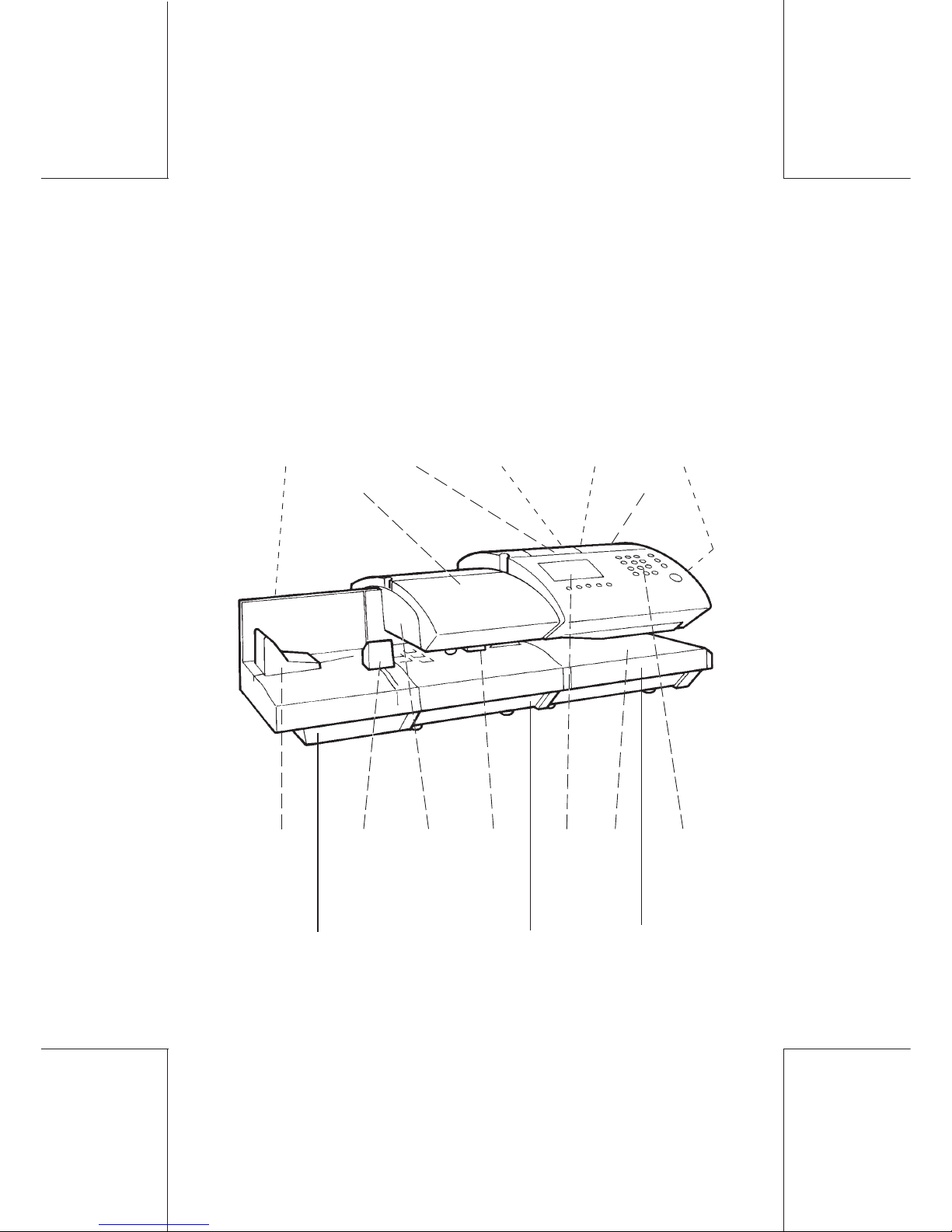
1.1.1 Overall view (mailing machine and optional standard automatic feeder)
cover
pre-cut
label
dispenser
touch
graphic
screen
keyboard
ON/OFF
switch
(rear)
memory
card
reader
adjustable
side
guide
conveyorfront
guide
cover
removable
rear
guide
accessories
and
documentation
area
feed
platform
autofeed
sealer
mailing
machine
table
modem
connector
(rear)
Overall presentation14
ORIG0140-14
4127718F/B
02/26/2007
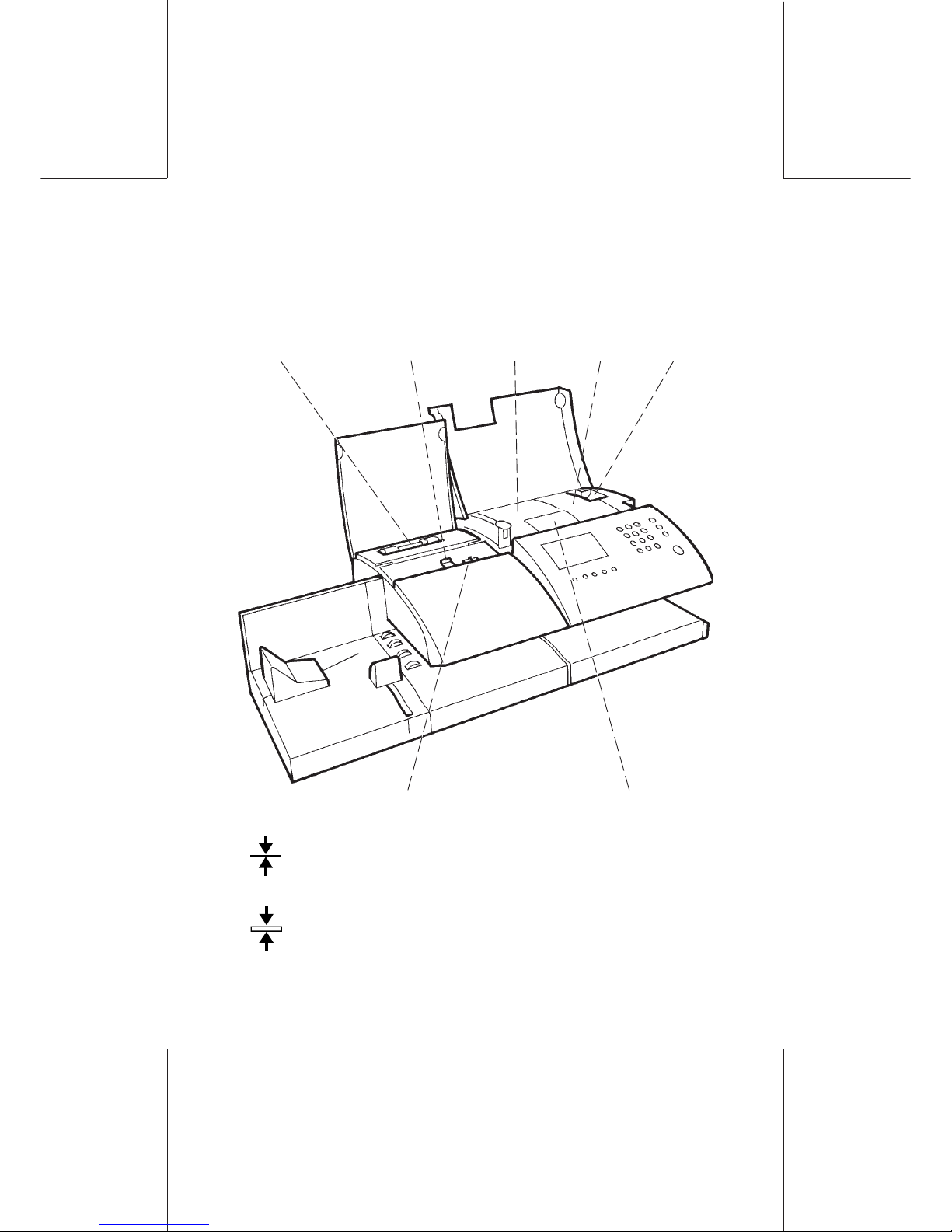
1.1.2 Overall inside view with optional standard
automatic feeder
postage
meter
ink
tank
blue button for
conveyor release
device
removable
water bottle
-
A
(left) : up to 3/8 inch
-
B
(right) : from 3/8 to 5/8 inch without the dynamic scale and
from 3/8 to 1/2 inch with the dynamic scale
label dispenser flap
thickness adjustment
2 positions blue button:
printhead
Overall presentation 15
ORIG0140-15
4127718F/B
02/26/2007
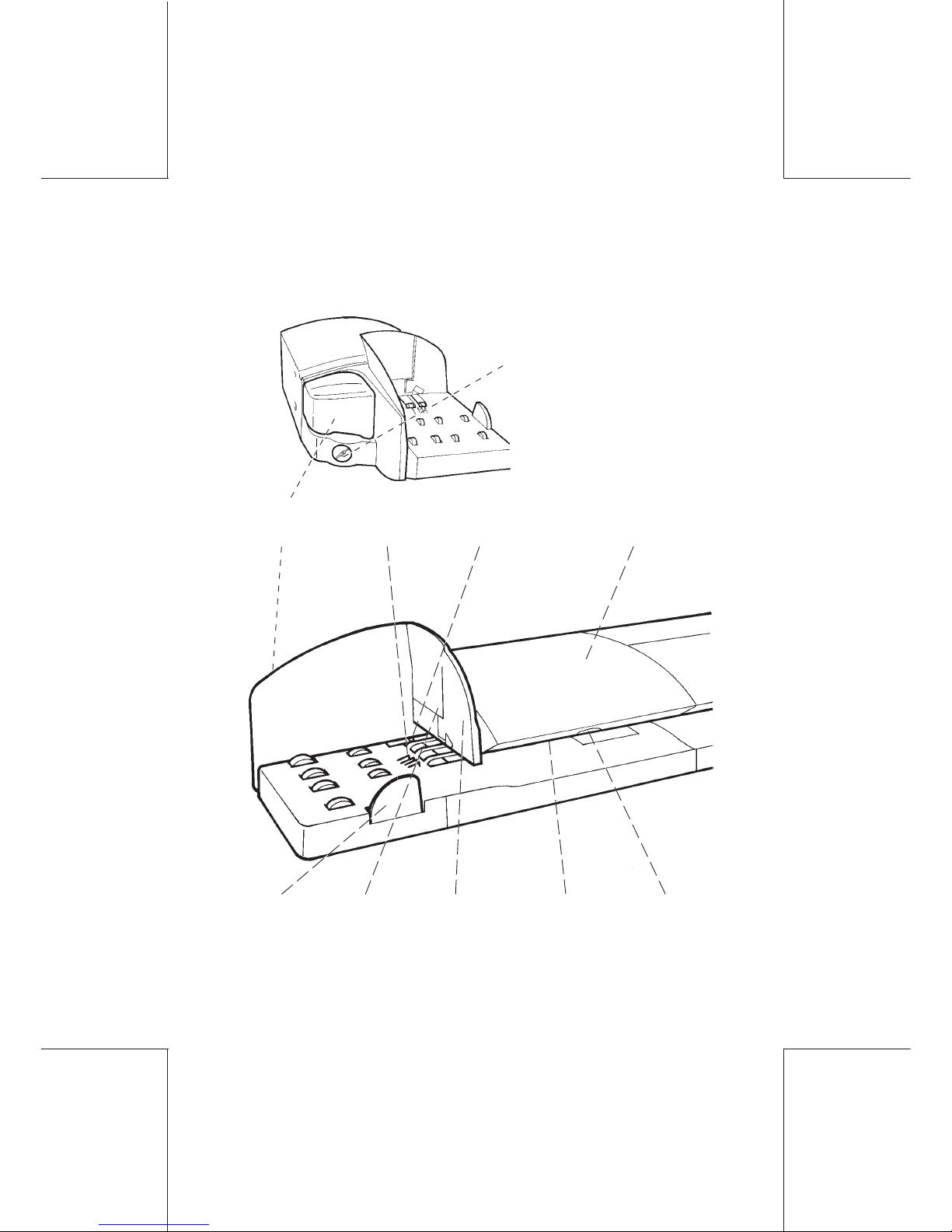
1.1.3 Mixed-mail feeder (optional)
cover
large
envelope
side guide
front
guide
small and
medium
envelope
side guide
water
bottle
anti-skew
levers
tightening
knob
cover
release
handle
conveyor
sensor
Overall presentation16
ORIG0140-16
4127718F/B
02/26/2007
0
0
.
0
0
0
LOW CREDIT
XX-XX-XX
LABEL SCALE SEALER
RATE
DEPT
MARKETING
TOI XXXXXX
BTO XXXXX
TEXT
LOGINJOBSMENU
INFO
AD DIE MAIL D
RATE NAME USER RATE
WGH MAN 30 lb 0.8 oz
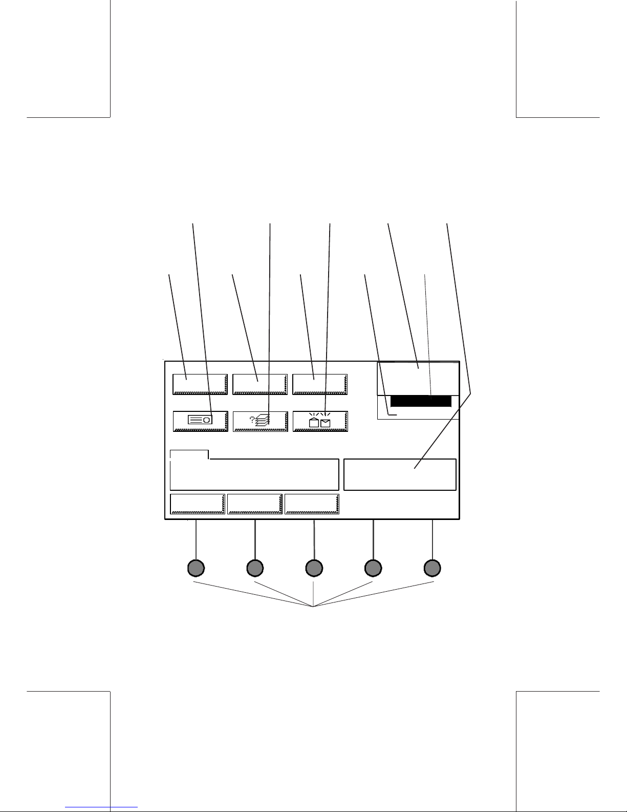
1.1.4 Touch screen and keyboard
advertisement
postage
value
date
menu selection keys,
or
touch keys on the screen
mail
class
die
warning
message
user
definable
parameter
to select
sealing
dynamic
scale
to select
RTD or
precut label
text
Overall presentation 17
ORIG0140-17
4127718F/B
02/26/2007
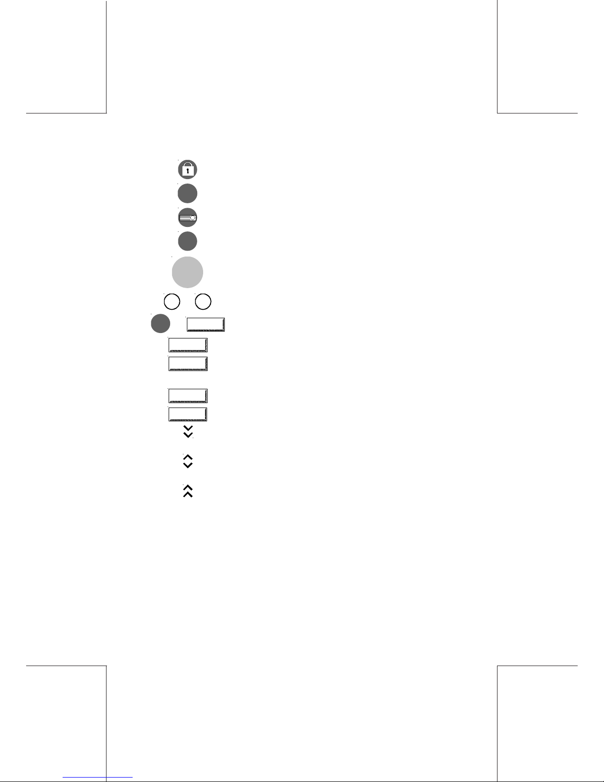
:locking and standby mode
RESET
: return to main menu with default settings
: label mode selection
C
: input value reset (including postage)
START
STOP
: switching on/off envelope or label feed
0
to
9
: numeric entry keys
OK
or
OK
: validating a selection
ESCAPE
:return to previous menu with no validation
HOME
:return to main menu with no validation (except
timeout)
LOGIN
:access to Supervisor mode every time
LOGOUT
:return to User mode
:indicates that there are other choices settable in
the next page
:indicates that there are other choices settable in
the next and previous pages
:indicates that there are other choices settable in
the previous page
Overall presentation18
ORIG0140-18
4127718F/B
02/26/2007
1.2 Installation
1.2.1 Preparation of the mailing machine
The mailing machine should be installed on a flat horizontal
surface.
Allow sufficient free space as follows:
- above the machine to enable the opening of the covers
- at the rear for the machine cooling.
With the O/I switch in the “ O ” (OFF) position, connect the power
cord to the rear of the machine and to an 110V AC electrical outlet.
Insert one end the telephone cable into the modem connector at
the rear of the machine and the other to an analog telephone wall
jack for Tele-Meter Setting® resetting connection.
For security purposes, please ensure that all the items are
correctly assembled prior to switch on the configuration.
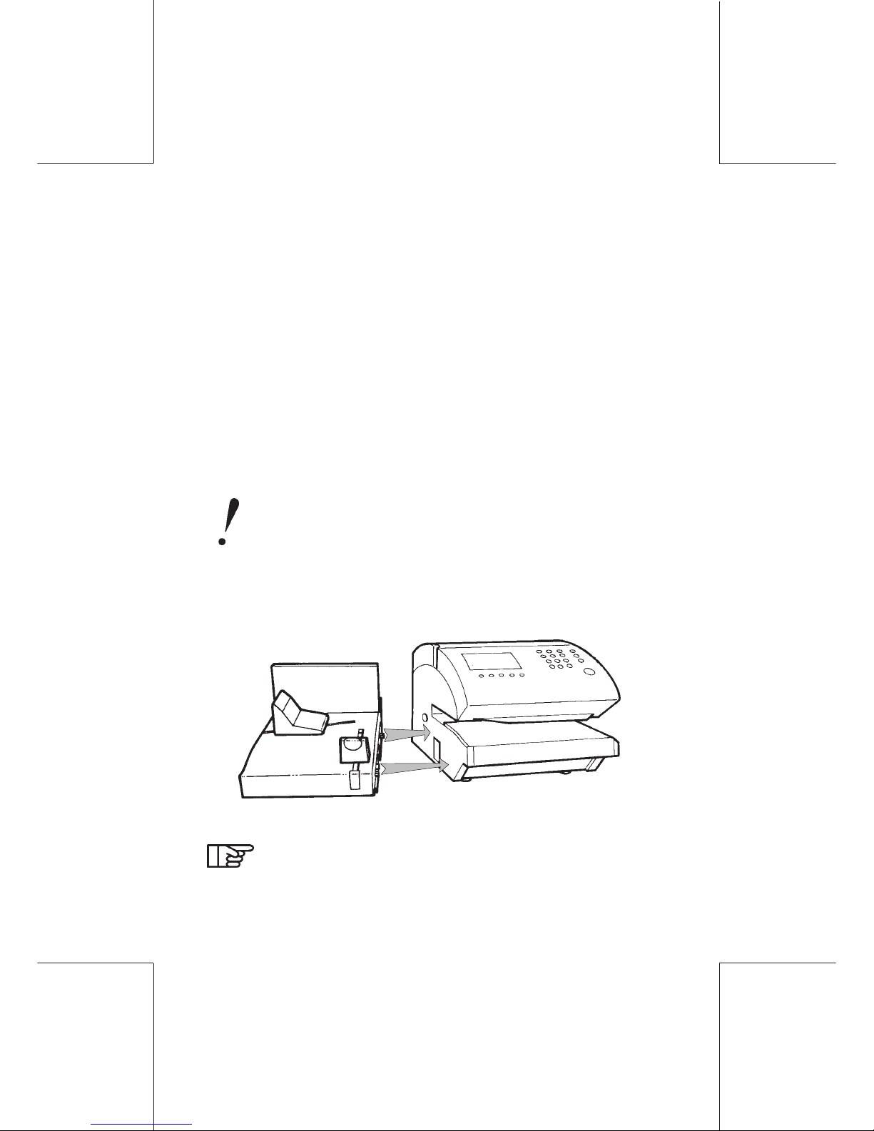
1.2.2 Installation with the feed platform
Assemble the feed platform with the mailing machine.
Prior to moving the whole machine, you must separate
the mailing machine from the feed platform.
Overall presentation 19
ORIG0140-19
4127718F/B
02/26/2007
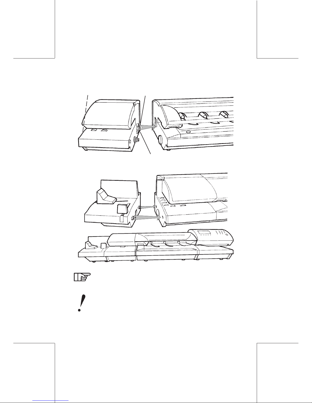
1.2.3 Installation of the standard automatic feeder
(optional: available on WJ185 only)
- Align the feeder with the mailing machine;
- Push the feeder towards the machine, taking care to keep the
centering pin aligned as indicated;
- Thread the feeder screw in the mailing machine. Then, using the
knurled tightening knob, push and screw to lock (if the two
devices are not closing properly, slightly rotate the gear protruding
from the feeder and repeat the operation).
centering pin
tightening knob
(on the side)
(gear)
Prior to moving the whole machine, the mailing machine,
the feeder and the platform must be separated.
- Assemble the feed platform with the feeder as indicated.
Overall presentation20
ORIG0140-20
4127718F/B
02/26/2007
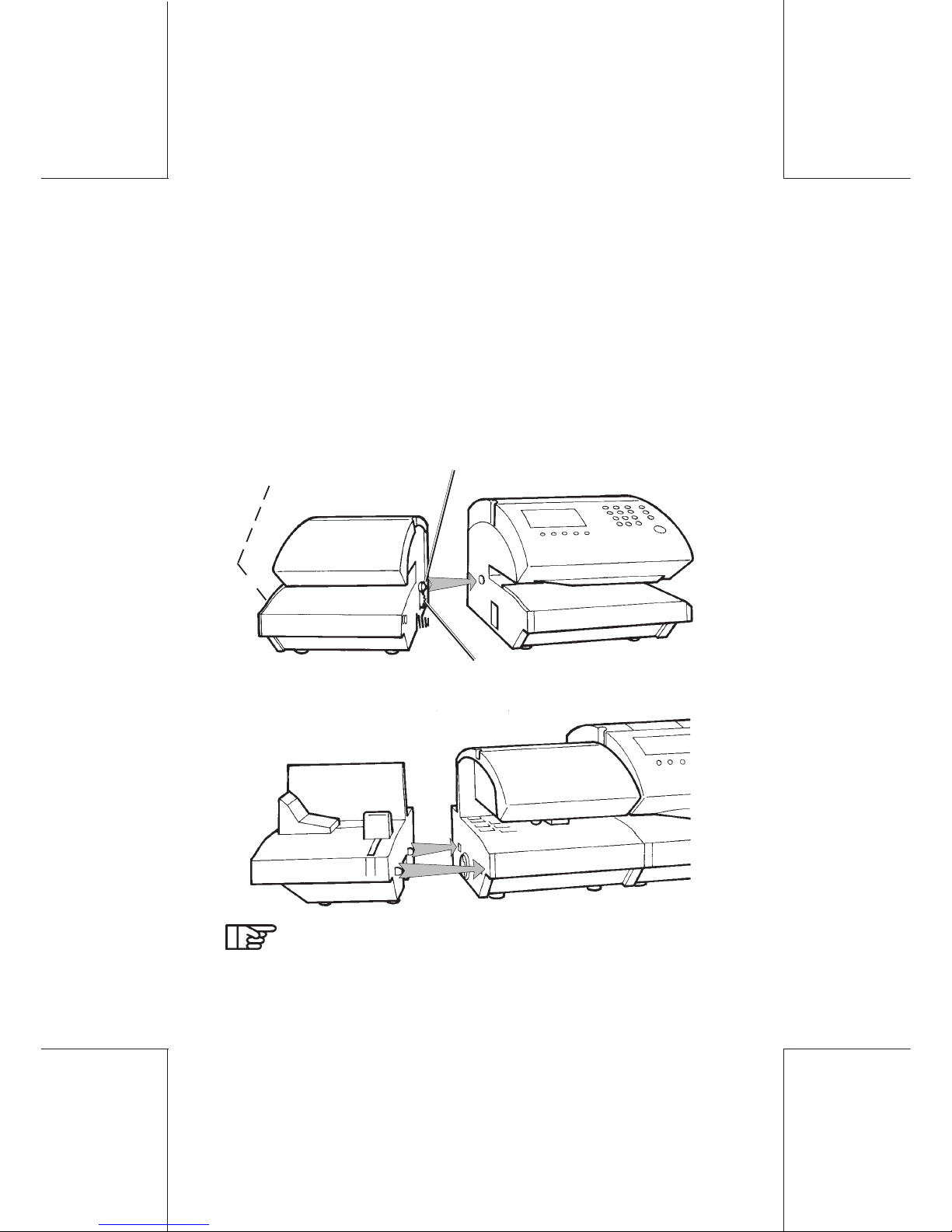
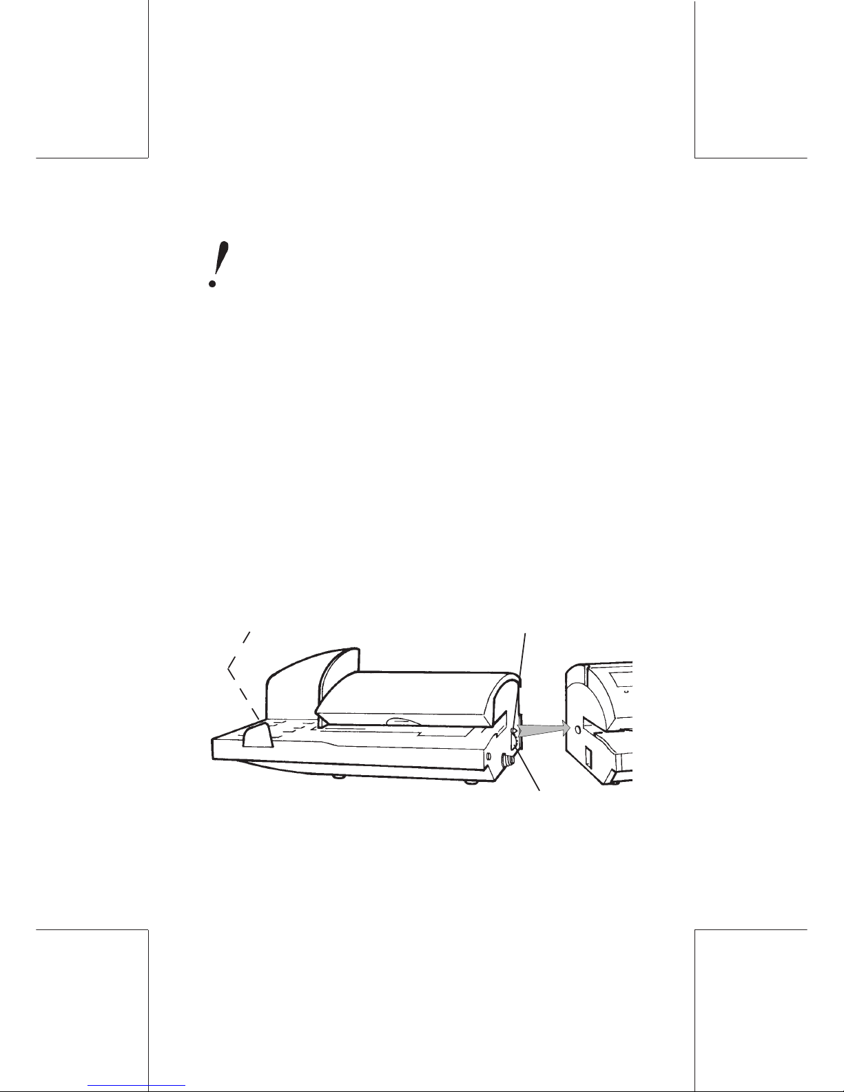
1.2.4 Installation of the mixed-mail feeder (optional)
The mixed-mail feeder operates with an optical sensor
next to the feed platform. Thus, it should not be installed
in an area exposed to any excessive light source.
- Align as much as possible the feeder with the mailing machine;
- Push the feeder towards the mailing machine (or the dynamic
scale), taking care to keep the alignment using the centering
pin;
- Insert the feeder screw into the mailing machine (or the dynamic
scale), then using the knob, tighten while pressing the screw to
lock it (if the units are not properly brought close together, gently
turn the gear protruding from the feeder and repeat the procedure):
centering pin
tightening knob (on the side)
(gear)
Overall presentation 21
ORIG0140-21
4127718F/B
02/26/2007
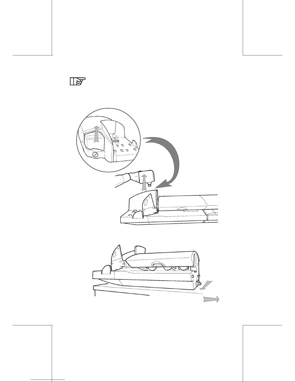
When the whole assembly needs to be moved, the units
should be separated:
-Separate the units;
-Disconnect the cables at the rear;
-Remove the feeder water bottle;
-Move the feeder to the edge of the table;
Cont'd
Overall presentation22
ORIG0140-22
4127718F/B
02/26/2007
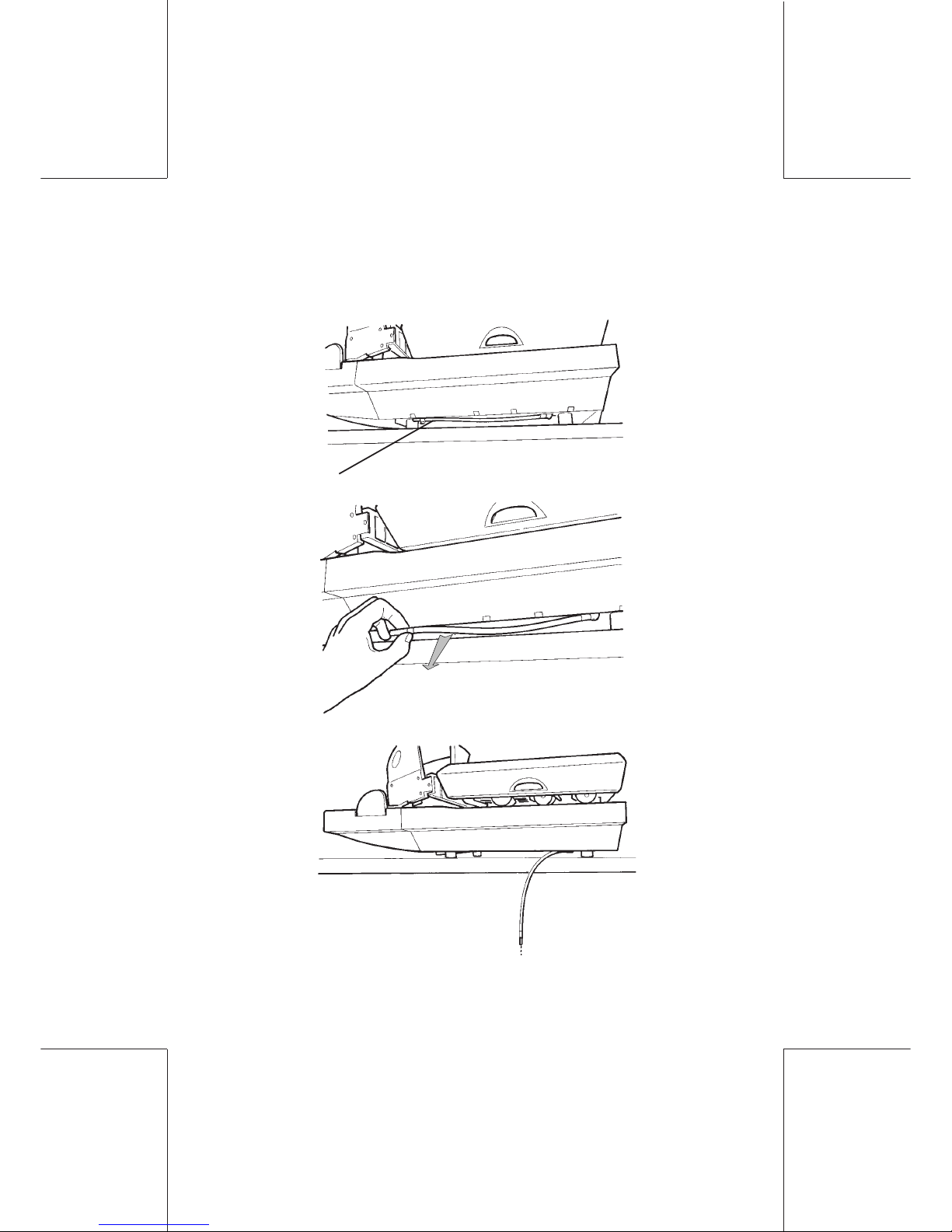
-take the pipe under the unit and remove the plug (hold
the pipe upwards so as not to get wet);
-empty the water remaining the feeder;
pipe
-insert the plug and put the pipe back in its place.
Overall presentation 23
ORIG0140-23
4127718F/B
02/26/2007
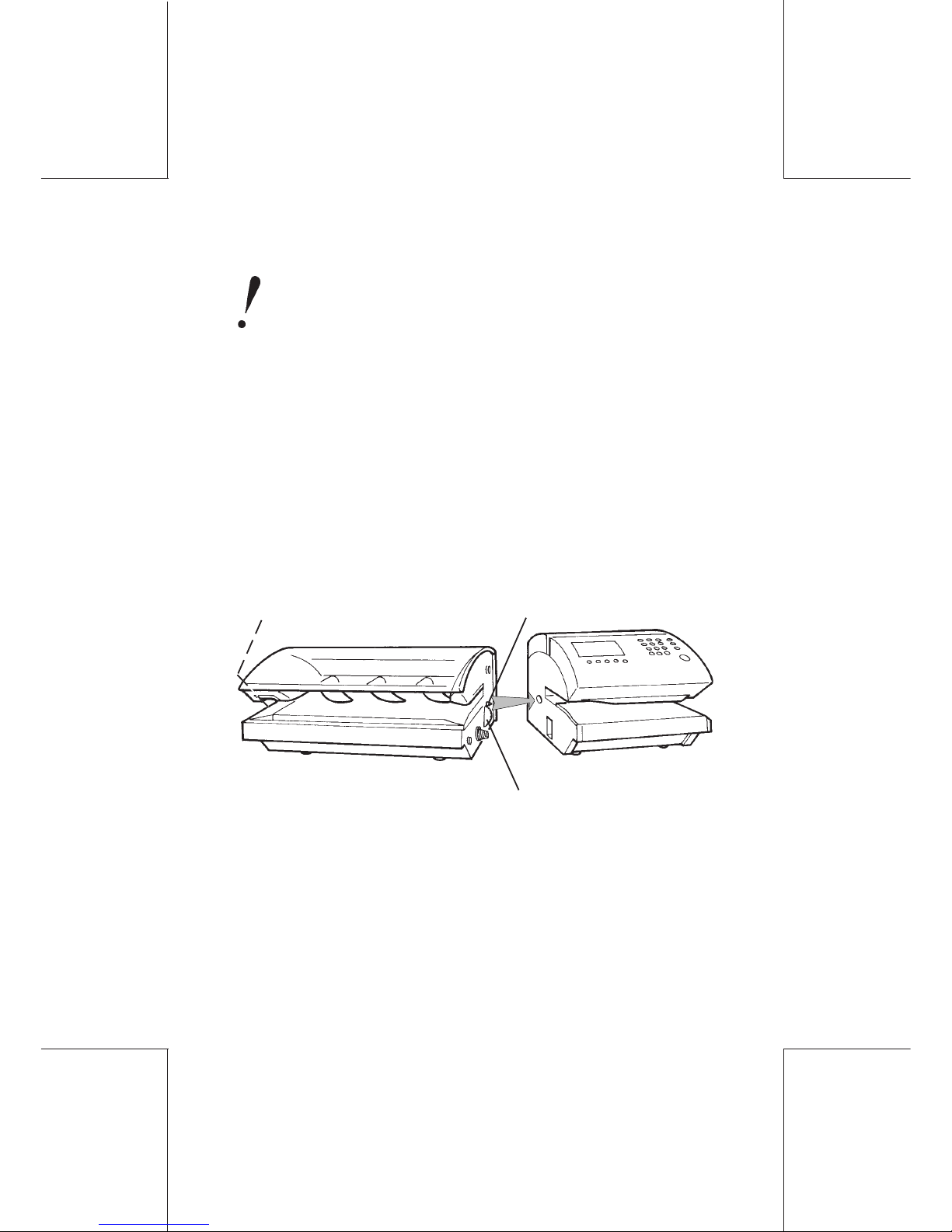
1.2.5 Installation of the dynamic scale (optional)
The equipment including a dynamic scale (the whole
system representing approximately 120 lbs) requires the
use of a steady and rigid table, in order to prevent any
weighing problem. Be sure not to install the machine in
an area exposed to the sunlight or to excessive air
currents.
- Align the dynamic scale with the mailing machine;
- Push the dynamic scale towards the machine, taking care to
keep the centering pin aligned as indicated;
- Thread the dynamic scale screw in the mailing machine. Then,
using the knurled tightening knob, push and screw to lock (if the
two devices are not closing properly, slightly rotate the gear
protruding from the dynamic scale and repeat the operation).
centering pin
tightening knob
(on the side)
(gear)
- Align the feeder with the dynamic scale;
- Push the feeder towards the dynamic scale, taking care to keep
the centering pin aligned as indicated;
- Thread the feeder screw in the dynamic scale. Then, using the
knurled tightening knob, push and screw to lock (if the two
devices are not closing properly, slightly rotate the gear protruding
from the feeder and repeat the operation).
Overall presentation24
ORIG0140-24
4127718F/B
02/26/2007
When the whole system needs to be shifted manually, the
mailing machine, the dynamic scale, the feeder and the
platform should be separated from one another.
When the machine is to be moved using any mechanical
equipment, please, contact the customer service.
centering pin
tightening knob
(on the side)
(gear)
- Assemble the feed platform with the feeder as indicated:
Whole configuration
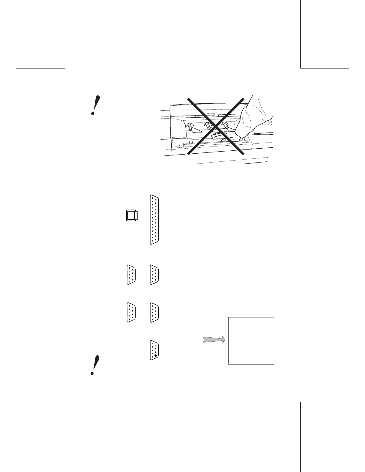
Overall presentation 25
ORIG0140-25
4127718F/B
02/26/2007
be sure to install
the black
terminator plug
on the feeder
connector when
the feeder or the
dynamic scale is
not used .
Printer
Feeder,
Dynamic
Scale,or
Terminator
Port 4:
-PC
- RTD (Roll tape dispenser)
- Scanner
- Scale
- Weighing Platform
A connection error may generate a failure.
Do not apply
pressure on the
dynamic scale
tray.
1.2.6 Connections at the rear of the units
Connections at the rear of the mailing machine
Modem
Port 2:
-PC
- RTD
- Scanner
- Scale
- Weighing
Platform
Port 1:
- PC (PC link and /or Reports to PC)
- Scanner
- Scale
- Weighing Platform
Port 3:
-PC
- Scanner
- Scale
- Weighing
Platform
²
Overall presentation26
ORIG0140-26
4127718F/B
02/26/2007
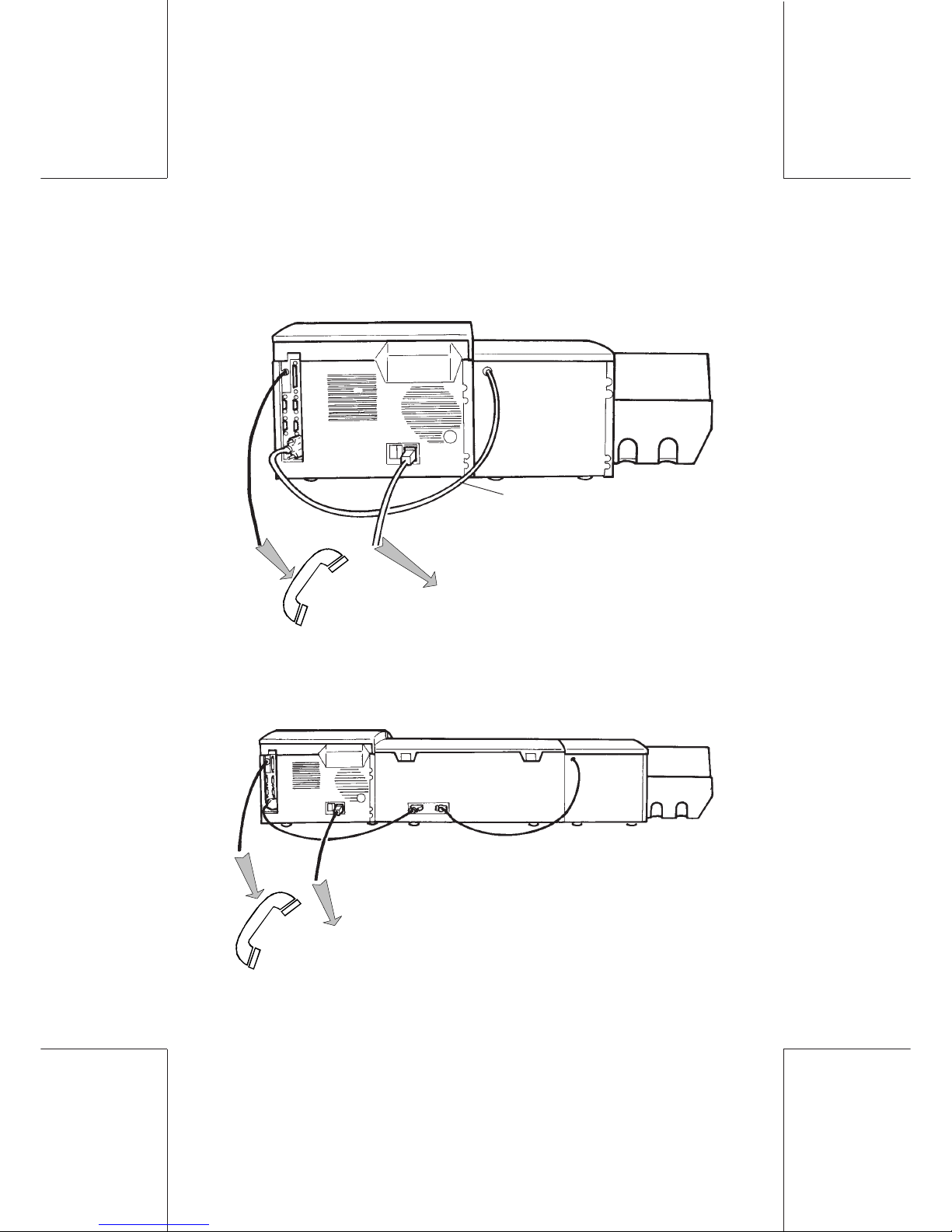
Connections with a standard automatic feeder
The feeder will automatically be switched on at the same time as
the mailing machine.
AC power outlet
Feeder
connection
cable
Connections with a standard automatic feeder and a
dynamic scale
The feeder and the dynamic scale will automatically be switched
on at the same time as the mailing machine.
AC power outlet
Overall presentation 27
ORIG0140-27
4127718F/B
02/26/2007
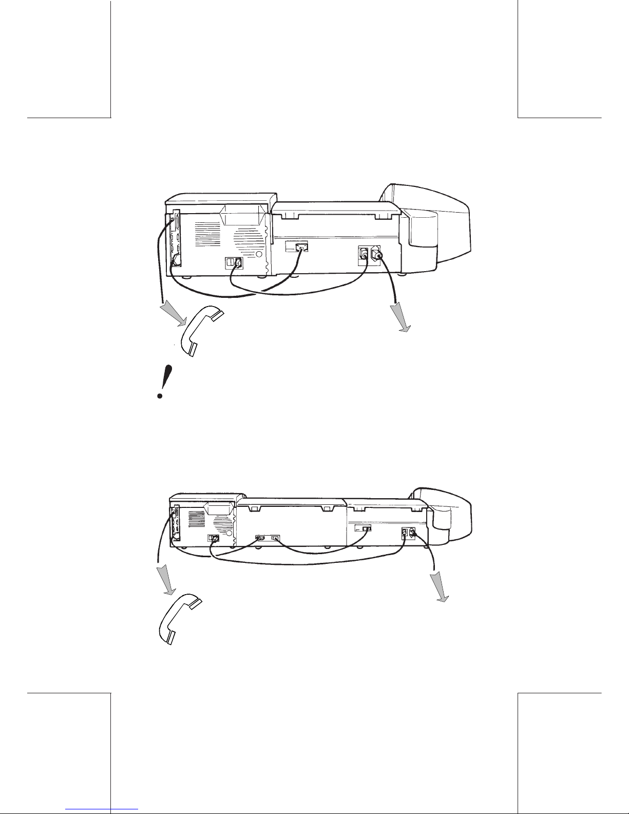
power outlet
Connections with a mixed-mail feeder
Connections with a mixed-mail feeder and a dynamic
scale
The dynamic scale will automatically be switched on at the same
time as the mailing machine.
power outlet
The mixed-mail feeder remains energized (when
connected to the power outlet) even if the mailing machine is turned off.
Overall presentation28
ORIG0140-28
4127718F/B
02/26/2007
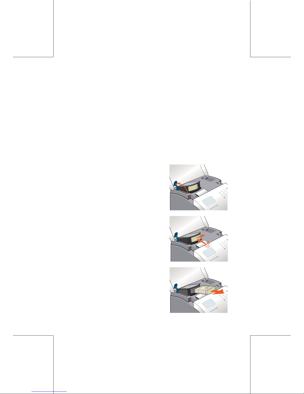
1.2.7 Ink tank and printhead
- When the message "ink low" is displayed, it is possible to
continue to print;
- When the message "ink very low" is displayed, it is possible to
continue to print, but it is strongly recommended to replace the
ink tank;
- When the message “ink out” appears, there is no more possibility
to print.
INK TANK REPLACEMENT (WJ220/110)
- Open the top cover and lift up the
blue lever;
- Press on the front of the ink cartridge
(1), then on the right hand side (2) in
order to remove it;
- Remove it;
(2)
(1)
Overall presentation 29
ORIG0140-29
4127718F/B
02/26/2007
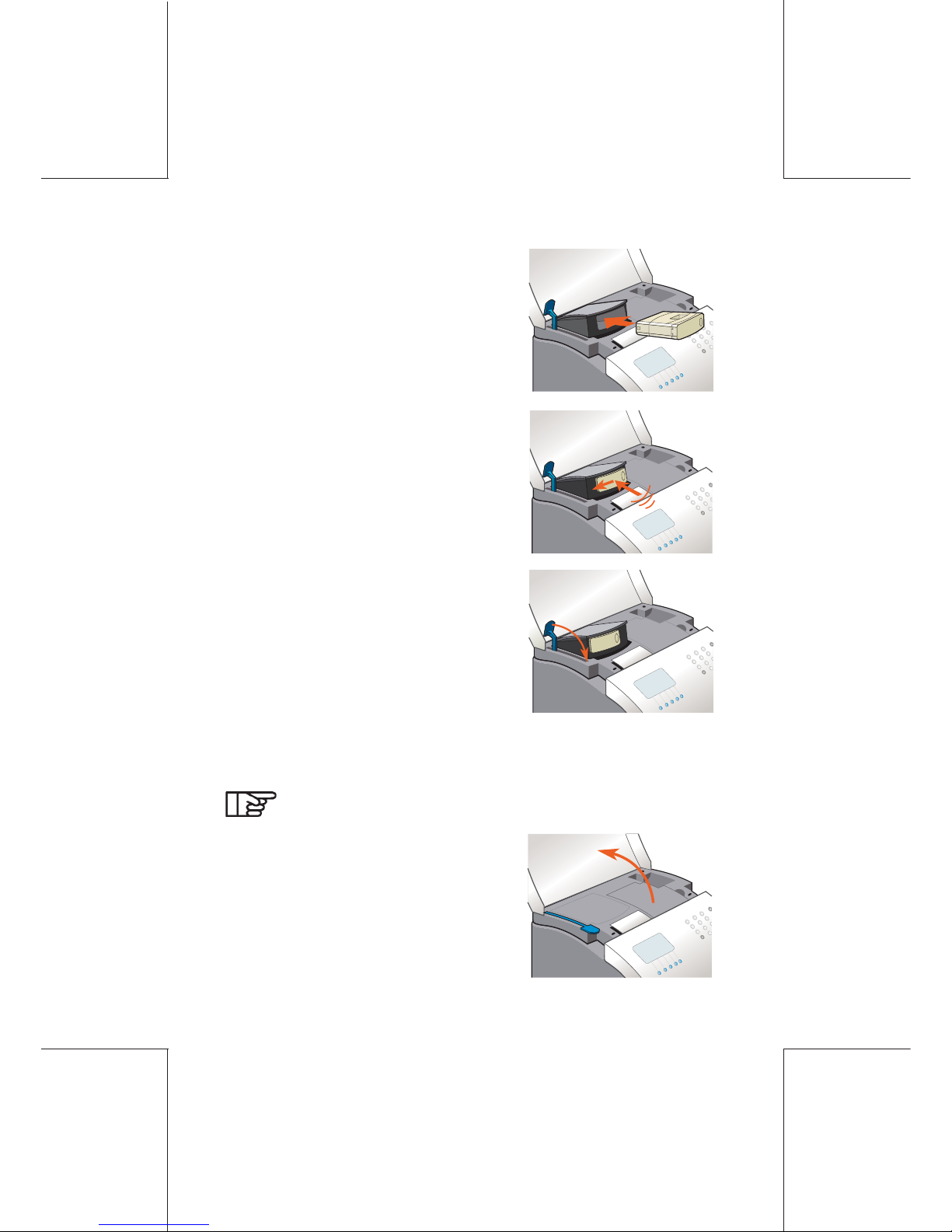
- Open the top cover and printhead
cover: the printhead will move to the
“replacement” position;
- Insert the new ink cartridge;
- Press on the front of the ink cartridge
(1), then on the left hand side (2) in
order to lock it;
- Lay down the blue lever and close
the top cover;
PRINTHEAD REPLACEMENT (WJ185/220/250)
The machine must be switched on.
(2)
(1)
Overall presentation30
ORIG0140-30
4127718F/B
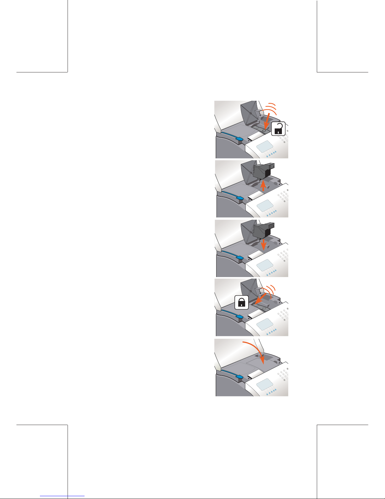
02/26/2007
- Press on the front of the printhead in
order to remove it;
- Remove it;
- Insert the new printhead;
- Lock it in position by pinching the
rear of the printhead;
- Close the printhead cover and top
cover (the printhead is automatically
reset in the “protection” position).
 Loading...