

Page 1
Jiffy®
J-4000 Model Steamer
FEATURES
• Built-in, easy-to-read sight gauge also indicates sediment
build-up
•
Cast
aluminum housing unit for durability
• Corrosion-proof stainless steel boiler tank--no
hard
become clogged with
• Dual thermostats for preheat
• Safety wiring feature temporarily
accidentally
• Numerous steam head attachments available
• Backed by Jiffy®
steamer need repair, send it to
the unit within 24 hours from its arrival to our
run
dry
's
renowned
water
deposits
and
steam settings.
turns
the unit off should
customer
us
and we will repair
water
service--should
lines to
and
plant
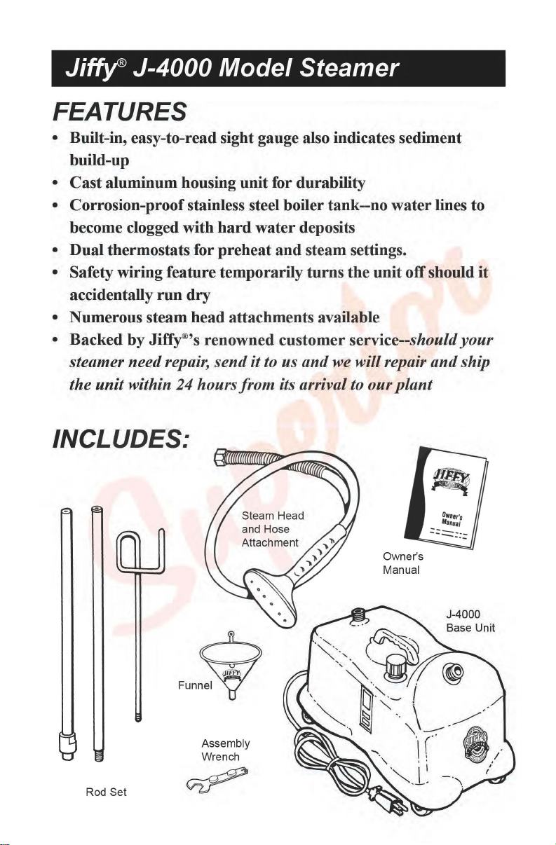
INCLUDES:
it
your
ship
Owner's
Manual
J-4000
6
Funne~
Assembly
Wrench
Rod Set
Page 2
Jiffy®
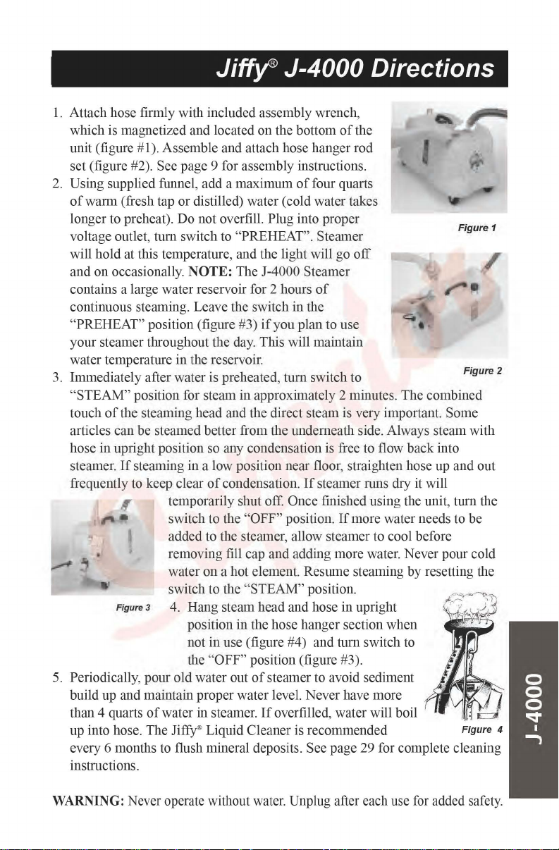
1.
Attach hose firmly with included assembly wrench,
which is magnetized and located on the bottom
unit (figure #1). Assemble and attach hose hanger rod
set (figure #2). See page 9 for assembly instructions.
2.
Using supplied funnel, add a maximum
of
warm (fresh tap or distilled) water (cold water takes
longer to preheat). Do not overfill. Plug into proper
voltage outlet, tum switch to "PREHEAT". Steamer
will hold at this temperature, and the light will go
and on occasionally.
contains a large water reservoir for 2 hours
continuous steaming. Leave the switch in the
"PREHEAT" position (figure #3)
your steamer throughout the day. This will maintain
water temperature in the reservoir.
3.
Immediately after water is preheated,
"STEAM" position for steam in approximately 2 minutes. The combined
touch
of
the steaming head and the direct steam is very important. Some
articles can be steamed better from the underneath side. Always steam with
hose in upright position so any condensation
steamer.
frequently to keep clear
5.
Periodically, pour old water out
build up and maintain proper water level. Never have more
than 4 quarts
up into hose. The JiffY' Liquid Cleaner is recommended
every 6 months to flush mineral deposits. See page 29 for complete cleaning
instructions.
If
steaming in a low position near floor, straighten hose up and out
Figure3 4. Hang steam head and hose in upright
NOTE:
temporarily shut off.
switch to the "OFF" position.
added to the steamer, allow steamer to cool before
removing fill cap and adding more water. Never pour cold
water on a hot element. Resume steaming by resetting the
switch to the "STEAM" position.
position in the hose hanger section when
not in use (figure #4) and tum switch to
the
of
water in steamer.
The J-4000 Steamer
of
condensation.
"OFF" position (figure #3).
J-4000 Directions
of
the
of
four quarts
off
of
if
you plan to use
tum
switch to
is
free to flow back into
If
steamer runs dry
Once finished using the unit, tum the
If
more water needs to be
of
steamer to avoid sediment
If
overfilled, water will boil
it
will
Figure 1
Figure
2
WARNING: Never operate without water. Unplug after each use
for
added safety.
Page 3

Jiffy®
J-4000 Parts Diagram
Should you ever need replacement parts for your
Ji~
Steamer, you may
purchase them separately. Use this handy diagram and parts list to identify any
part you may need. Please include model and serial number when ordering.
Jiffy
Key#
1
2
Steamer
Part
#
1030
1034
0035
Part
Description
Rod
Set
and
Rod
Set
and
Hook
Section
Nut
Complete with
Nut
Complete
of
Rod
Set
for
Drapery
Metal
Studs
Steamers
Price
$
$
$
List
25.50
29.00
6.50
Page 4

Jiff~
J-4000 Parts Diagram
Key
3
4
5
6
7
8
9
10
11
12
13
14
15
16
17
18
19
20
21
22
23
24
25
26
27
28
29
30
ACCESSORIES
31
0036
0037
0038
0043
0039
1031
1032
0253
0251
0280
1301
0006
0049
0053
0054
0199
0201
1310
1311
0133
0146C
0050
1353
1354
1374
0074
0074A
0058
0071
0061
0062
0075
1355
1356
1350
1351
1352
1362
0203
1314
1320
0017
0018
1050
0259
0257
0252
0255
0254
0256
0269
0262
0274
1062
1063
0898
Middle
Section
of
Bottom
Additional
Metal
Threaded
Metal
Threaded
1/2"
Split
Rod
Set
Plastic
Plastic
Hose
Per
J-4000
Hex
Beauty
Water
Fill
Funnel
Housing
Rotary
Replacement
Red
Neon
Red
Neon
Cord
Set
Cord
Strain
Water
Level
Stainless
Stainless
Stainless
Stainless
Stainless
Boiler
Tank
Boiler
Tank
Boiler
Tank
Boiler
Tank
Boiler
Tank
Heating
Heating
Heating
Heating
Control
Hardware
PreheatThermostat
Internal
Bottom
Bottom
Bottom
Jiffy
Steamer
Auto
Hose
Carpet
7.5' Drapery
7.5' Drapery
Metal
Head I Wood
Metal
Head I Wood
Replacement
Wig
Hose
Brass
Hat
Steam
Cleaning
Brush
Only
Liquid
Cleaner-3 Ten
*Not
Available
Rod
Section
of
Rod
Middle
Section
Cap
Stud
Ring
for
Rod
Nut
Steam
Head/Handle
Head/Handle
Foot
(Black
Die
Cast
Aluminum
Rings
(Set
Cap
Handle
with
Power Switch
Knob
Pilot
Light
Pilot
Light
(14/3
gauge) with
Relief
Sight
Gauge with
Steel
Boiler
Steel
Boiler
Steel
Boiler
Steel
Boiler
Steel
Boiler
Lid with 2 Brass
Screw Set
Silicone
Silicone
Gasket
Element
(120
Element
(230
Element
(120
Element
(230
Kit with
Seal
Kit
for
J-4000
Wire
Set
(Set
Plate with
Four
Plate
Scre
ws
Plate
Casters
Assembly
Attachment
Hose
Attachment
Hose
Attachment
Hose
Attachment
Wooden
Attachment
Nozzle
Attachment
"B"
for
the
"B"
for
Export.
Set
(with
Set
of
Screw
for
Rod
Set
Hose
Attachment
in
Color)
of
2)
Two
Scre
and
Knob
Only
for
(120
(230
Tank
Tank
Tank with
Tank with
Tank with
(Set
Sealer
Sealer
Volt, 1500
Volt, 1500
Volt, 1500
Volt,
and
Hardware
Control
(L-170)
of 4 Wires)
Casters
(Set
of
(Set
Wrench
with
with 12" w
Handle
Handle
Handle
Brush
Hose
Hose
(10)
Barrel
Stud
Rod
Set
for
for
Rod
Set
Sections
Replacement
Housing
VOLT)
VOLT)
Strain
Kit
Kit
of
(2.8
(10.1
1500
of
Dual
Hose
Only
Attachment
Ounce
ws
Rotary Pow
Relief
Nuts
and
Complete
Complete
Sight
Gauge
Sight
Gauge
Sight
Gauge
Fittings
and 2 Beauty
30
+ 1
Tee
Fluid
Ounces)
Fluid
Watt)
Watt)
Watt) & Control
Watt) & Control
4)
4)
Metal
ide
with
Plastic
with
Metal
Attachment
(for
Metal
Attachment
Bottles
Complete
and
Drapery
Kit
er Switch
Washers
(120
Volt)
(230
Volt)
(J-4000)
(J-3)
(J-4)
Nut)
Ounces)
Heads
Metal
Head
Steam
Steam
Complete
Steam
per
Cap
Screw)
Steamers
Rings
Kit
Complete $ 46.00
Kit
Complete $ 46.00
Head
Head
Heads)
Package*
$
$
$
$
$
$
$
$
$
$
$
$
$
$
$
$
$
$
$
$
$
$
$
155.00
$
155.00
$
$
$
$
$
$
$
$
$
$
$
$
$
$
$
$
$
$
$
$
$
$
$
$
$
$
$
$
$
$
7.50
7.50
7.50
1.50
1.50
0.50
6.00
22.00
50.00
3.00
72.00
1.50
6.50
3.50
7.00
12.00
1.50
4.50
4.50
9.50
1.50
32.00
78.00
46.00
78.00
28.00
6.00
4.50
8.00
8.50
28.00
28.00
18.00
1.50
8.00
8.00
18.00
0.75
6.50
4.00
82.00
75.00
56.00
76.00
70.00
37.50
7.00
50.00
13.00
50.00
8.00
15.00
Page 5

Jiffy®
J-4000 Wiring Diagram
Caution:
Insure
outlet before
that
the power
attempting
cord
is unplugged from
to
repair
your
the
electrical
Jiffy® Steamer.
..
....
.!!
,I
Flliru
om
mer
~i
ng
m
(
,
!'t
~ [nu
Page 6

Jiffy®
J-4000 Wiring Instructions
Please note, the switch terminal numbers and the switch
terminal letters are marked on the actual switch.
1.
Neutral wire
marked
2.
Positive wire #2 (black wire from cord set bundle) attaches to
the GE #ASR3282-05 rotary power switch.
3. Ground wire
steamer housing.
4. Ground wire #4 (green wire from electrical control) attaches to the
aluminum steamer housing.
5.
The double white wire
follows:
6.
Blue wire #6 connects switch terminal number 1 to the top side
PREHEAT thermostat.
7. Triple yellow wire #7 connects from the bottom side
thermostat as follows:
#1
(white wire from the cord set bundle) attaches to "A"
on
the GE #ASR3282-05 rotary power switch.
#3
(green wire from cord set bundle) attaches to the aluminum
#5
connects from switch terminal number 4 as
• The 5A leg
terminal pin on the right side
which is the one nearest to the ground wire.
• The 5B leg
either side
• The 7 A leg
number
• The 7B leg
• The 7C leg
R34 electrical control.
of
the double white wire
of
of
the double white wire
of
the red pilot light.
of
the triple yellow wire #7 goes to switch terminal
2.
of
the triple yellow wire #7 goes to the red pilot light.
ofthe
triple yellow wire #7 goes to the left side
#5
connects to the
the R34 electrical control,
#5
connects to
of
the
"B"
Ll70
marked on
of
the L-170
PREHEAT
of
the
 Loading...