

Page 1
Jiffy®
J-2000 Model Steamer
FEATURES
• Polymer
outer
housing unit for
durability
• Lightweight, flexible hose
•
Shatterproof
• Safety wiring feature
accidentally
water
run
caddy
temporarily
dry
turns
• Comfortable, easy-to-grip handle
• Removes wrinkles
up
to five times faster
ironing
• Easy-roll casters for mobility
• Numerous steam
• Backed
by
Jiffy®
steamer need repair, send it to
head
attachments
's
renowned
available
Customer
us
and
we will repair and ship
Service--should
the unit within 24 hours from its arrival to our
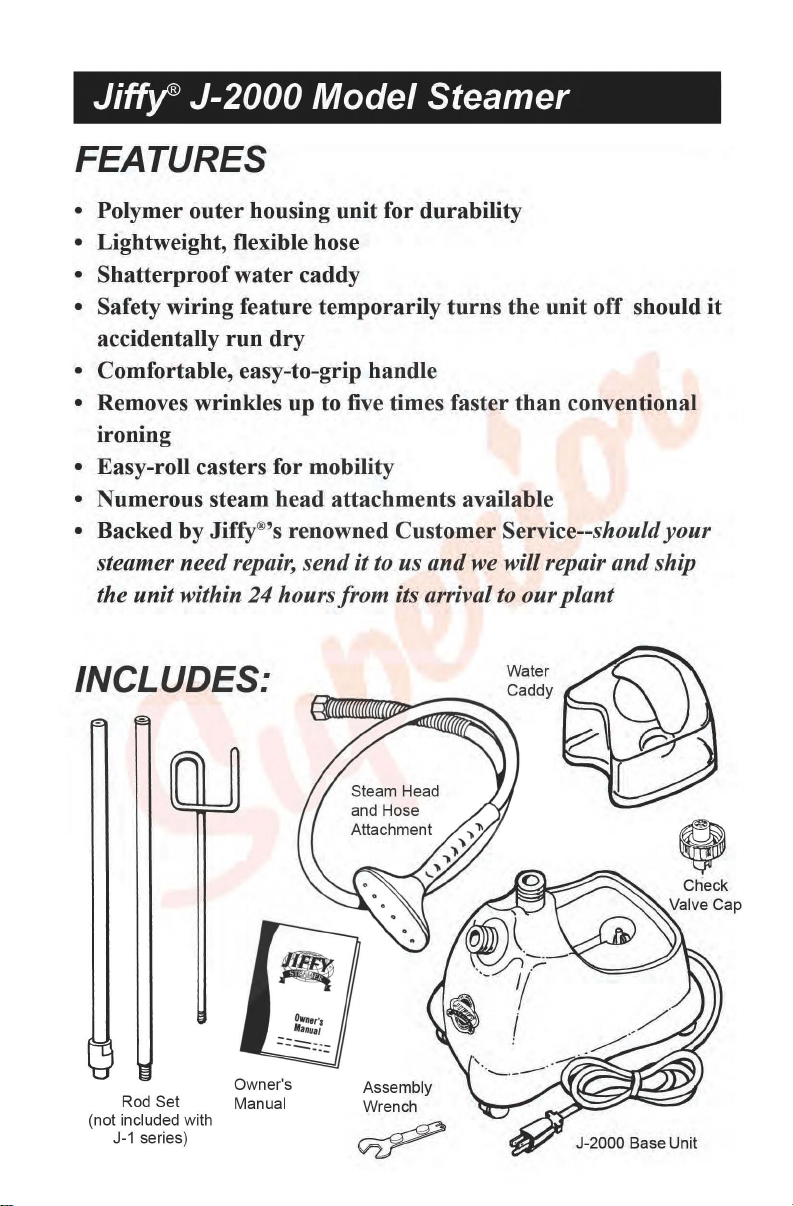
INCLUDES:
the unit off should
than
conventional
your
plant
it
Check
Rod Set
(not included with
J-1
series)
Owner's
Manual
J-2000
Base Unit
Page 2
Jiffy®
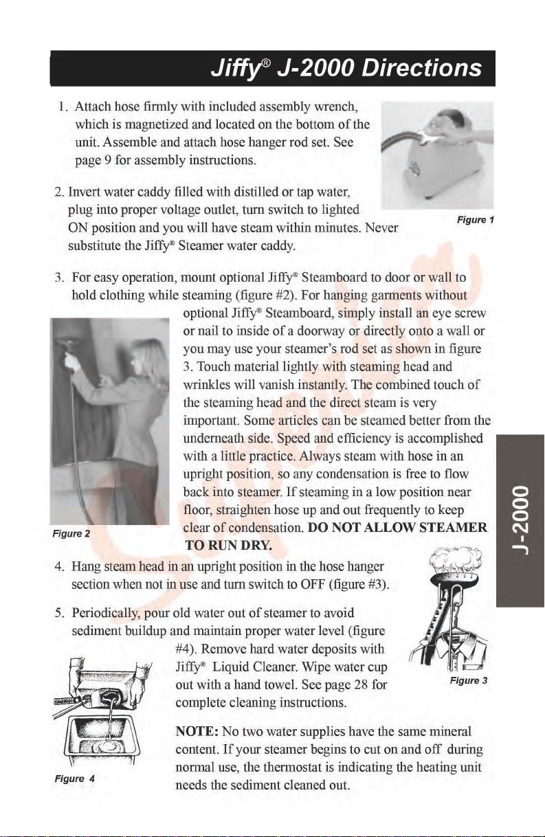
1.
Attach hose firmly with included assembly wrench,
which is magnetized and located
J-2000 Directions
on
the bottom
unit. Assemble and attach hose hanger rod set. See
page 9 for assembly instructions.
2.
Invert water caddy filled with distilled or tap water,
plug into proper voltage outlet,
ON
position and you will have steam within minutes. Never
turn
switch to lighted
substitute the Jiffy® Steamer water caddy.
of
the
Figure 1
3. For easy operation, mount optional
Ji~
Steamboard to door or wall to
hold clothing while steaming (figure #2). For hanging garments without
optional
or nail to inside
you
Ji~
Steamboard, simply install an eye screw
of
a doorway or directly onto a wall or
may
use your steamer's rod set as shown in figure
3. Touch material lightly with steaming head and
wrinkles will vanish instantly. The combined touch
the steaming head and the direct steam is very
important. Some articles can be steamed better from the
underneath side. Speed and efficiency is accomplished
with a little practice. Always steam with hose in
upright position, so any condensation is free to flow
If
back into steamer.
steaming in a low position near
floor, straighten hose up and out frequently to keep
Figure 2
condensation.
DO
NOT ALLOW STEAMER
clear
of
TO RUN DRY.
4.
Hang steam head in an upright position in the hose hanger
section when not in use and tum switch to
5.
Periodically, pour old water out
of
OFF (figure #3).
steamer to avoid
sediment buildup and maintain proper water level (figure
#4). Remove hard water deposits with
Ji~
Liquid Cleaner. Wipe water cup
out
with a hand towel. See page 28 for
complete cleaning instructions.
of
an
Figure3
Figure 4
NOTE:
content.
normal use, the thermostat is indicating the heating unit
needs the sediment cleaned out.
No
two water supplies have the same mineral
If
your steamer begins to cut
on
and
off
during
Page 3

Jiffy®
J-2000 Parts Diagram
/
i ;
i I
i
/
'
\.
'
\.
I '
9 / \
' '
; 10)
!
,/
' ;
! ;
/.
,/
"\
'
'
'
'
'
·-·-19 \
\ 25
~,,'',,,
\
/\
;
i
'
i
Should you ever need replacement parts for your
J~
Steamer, you may
purchase them separately. Use this handy diagram and parts list to identify any
part you may need. Please include model and serial number when ordering.
Page 4

Jiff~
Jiffy
Key#
1
2
3
4
5
6
7
8
9
10
11
12
13
14
15
16
17
18
19
20
21
22
23
24
25
26
27
28
ACCESSORIES
29
Steamer
Part#
1030
0035
0036
0037
0043
0039
1031
1032
0253
0251
0280
1100
1140
1141
0027A
0004
1125
1126
0132
0146B
0148
1193
1194
01618
01628
0030
1130
0187
0160
0195
0151
1120
0011
0010
1050
0254
0256
0262
1062
1063
0898
J-2000 Parts Diagram Key
List
Part
Description
Rod
Set
and
Hook
Section
Middle
Section
Bottom
Section
Metal
Threaded
Metal
Threaded
1/2"
Split
Ring
Rod
Set
Nut
Plastic
Steam
Plastic
Head/Handle
Hose
Per
J-2000
J-2000
with
J-2000
with
Replacement
Round
Green
Green
Cord
Cord
Internal
Heating
Lighted
4
Heating
Lighted
4
Heating
Models
Cord
Heating
Models
230
Brass
3/8" x 1/4"
Heating
Copper
Compression
L-290
Fusible
Fusible
Bottom
Bottom
Screws
Jiffy
Metal
Metal
Wig
Steam
Brush
Liquid
'Not
Foot
Plastic
Water
Check
Water
out
Check
Beauty
Lighted
Lighted
Set ( 16/3
Strain
Wire
Unit
Contura
1/2"
Water
Unit
Contura
1/2"
Water
Unit
with
Set
and 4 1/2"
Unit
with
Volt
Cord
90
Degree
Straight
Element
Tube(41/2"
Thermostat
Link
Link
Plate
Plate
for
Steamer
Head/Wood
Head I Wood
Hose
Attachment
Cleaning "B"
Only
for
Cleaner-3 Ten
Available
Valve
Bottom
Nut
Complete
of
Rod
Set
of
Rod
of
Rod
Cap
Screw
Stud
for
for
Rod
Head/Handle
Hose
(Black
Housing
Caddy
Complete
Cap
Caddy
Complete
Valve
Cap
Check
Valve
Ring
Contura
Contura
gauge)
Relief
Set
Kit
(wiring
Rocker
Line
Kit
(wiring
Rocker
Line
Assembly
Green
Lighted
Water
Assembly
Green
Lighted
Set
and 4 1/2"
Elbow
Brass
Housing
length)
Rings
Clamp
Wire
with
with
Casters
Casters
Plate
Assembly
Handle
Handle
Brush
the
"B"
Hose
(10)
for
Export.
with
Set
Set
for
Rod
Sections
Set
Replacement
Attachment
in
Color)
Kit
Cap
Rocker
Rocker
with
Strain
included)
Switch
included)
Switch -230
(no
wiring
Rocker
Line
(no
wiring
Contura
Water
Joint
Fitting
with
Insulated
(Set
of
4)
(4
Screws
Wrench
Hose
Only
Hose
Attachment
Ounce
Metal
Studs
Rod
Set
Complete
Switch -120
Switch -230
Relief
for
Models
-120
Volt
for
Models
Volt
included)
Switch -120
included)
Rocker
Line
for
Nuts
and
Lug
Total)
Attachment
Attachment
Bottles
per
Kit
Volt
Volt
with
Green
Cord
Set
with
Green
Cord
Set
for
Volt
for
Switch
Complete
Package'
and
and
-
Price
$
25.50
6.50
$
7.50
$
7.50
$
1.50
$
1.50
$
0.50
$
6.00
$
$
22.00
$
50.00
3.00
$
$
58.00
$
28.00
$
24.25
3.75
$
0.75
$
9.00
$
9.00
$
9.50
$
1.50
$
9.00
$
$
81.50
$
81.50
$
62.50
$
62.50
2.50
$
2.50
$
4.00
$
8.00
$
1.50
$
3.00
$
$
18.00
6.50
$
0.75
$
4.00
$
$
70.00
$
37.50
$
50.00
$
50.00
8.00
$
$
15.00
Page 5

Jiffy®
J-2000 Wiring Diagram
Caution:
Insure
cord
the electrical outlet before
attempting
Jiff~
that
the power
is unplugged from
to
Steamer.
repair
your
Page 6

Jiffy®
J-2000 Wiring Instructions
Please note switch terminal numbers 2, 3, 5 and 6 indicated on
the enlarged switch diagram are marked on the actual switch.
Jiffy® Steamers manufactured before May
2000 are not
marked with the terminal switch numbers, but the terminal
blades are in the same location.
1.
Insert cordset into housing and connect white neutral wire from cordset
bundle to terminal number 5
2. Connect blue wire from the right side
of
the L-290 thermostat.
3.
Insert brass heating unit into housing and tighten with 2 mounting screws.
Connect green ground wire (from cordset) to the nearer
ing screws.
4. Connect black positive wire from cordset to plastic connector on orange
fusible link wire.
5.
Connect other end
on
the switch.
6. Connect yellow wire from the left side
number 3 on the switch.
7. Connect white wire from the left side
number 6 on switch.
8.
Insert one end
fitting at bottom
9.
Connect other end
elbow at bottom
may be loosened and adjusted for a better fit
10. Set steamer upright and place black plastic strain relief approximately
1
4
from end
12"
11. Secure bottom plate with four screws.
To
avoid leakage, be sure and tighten hose (or hat nozzle) with wrench
12.
before using steamer.
of
of
copper water line and compression ring into threaded
of
brass heating unit and tighten nut with a
of
water line with compression ring to 90 degree brass
of
water cup and tighten with a
of
cord and insert into housing using pliers.
on
the switch.
of
heating element to the right side
of
the two mount-
orange fusible link to terminal number 2
of
the thermostat to terminal
of
the heater unit to terminal
5
5
18"
wrench. (Heating unit
if
necessary.)
18"
wrench.
 Loading...