

Page 1
HASHIMA
[J-
ROTARY
IHif>=fBlOOlS=
INSTRUCTION .MANUAL
9
JfX
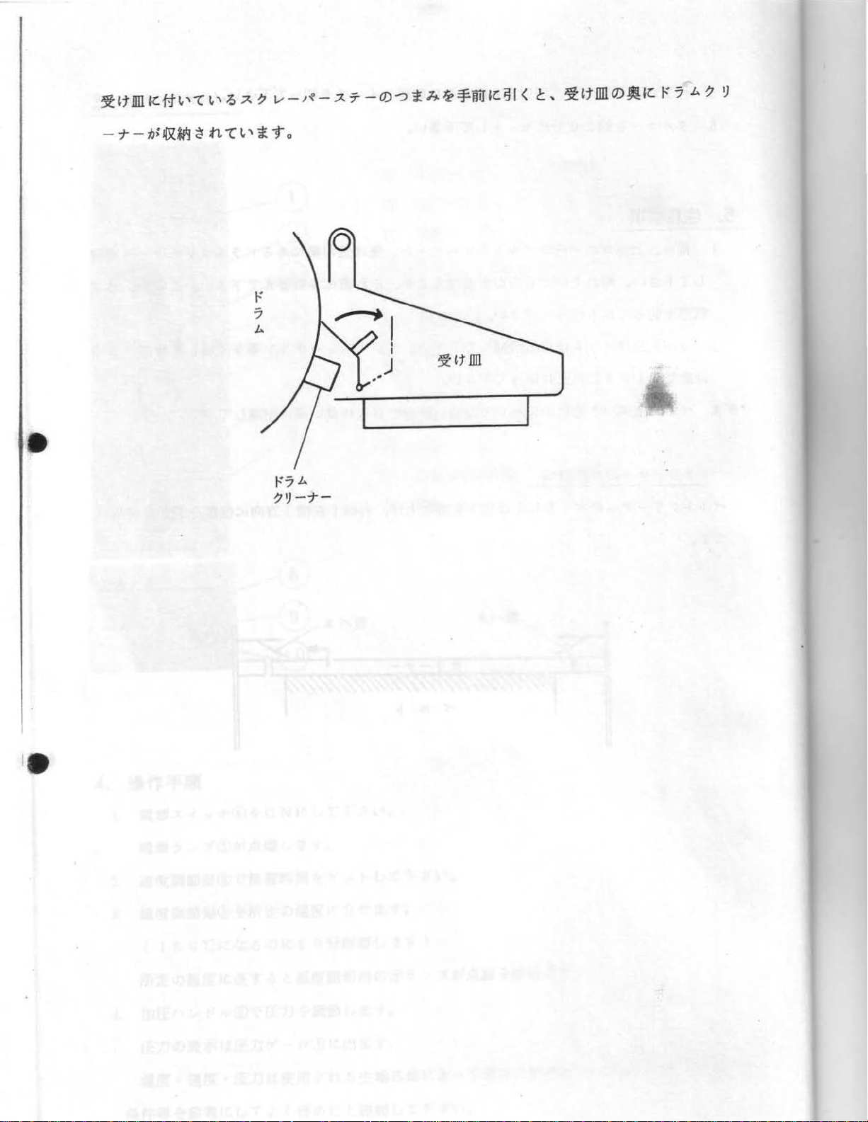
/'
IJ
-~Ji7°VA
FUSING
m
-
PARTS
\,
'/
\
~~
IJ
a~
A
LIST
PRESS
Jr
•
JD[
•
Page 2
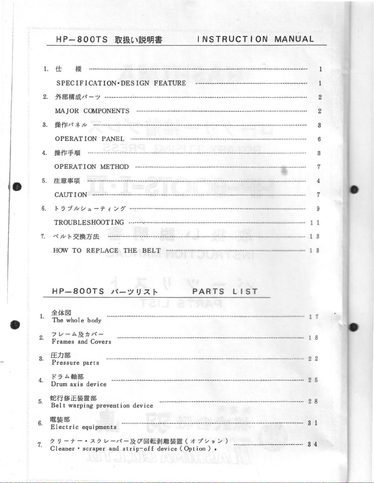
1.
tt
INSTRUCTION
"'
...........................................................................................................................
MANUAL
1
•
SPECIFICATION
2.
;1f.$n.J.IlJZre-
MAJOR
B.
1ifF1~
OPERATION
4.
~fF¥JIJili
OPERATION
6.
~~~Jj{
CAUTION
6.
f-
7 7
TROUBLESHOOTING
1.
-"'
;v
HOW
;f.
;v
1-
~mE
TO
C~ONENTS
)V
.................
.....................................................................................................
.................................... .....................................................
:_,
.:~.
REPLACE
·
DESIGN
':J ................ :.................................................................
...
..................................................................................................
PANEL
................................................................................................... 6
................................................................
METHOD ................................................................. -
- 7
-1
/
7'
.............................................................................
....... , ....................... ............................. .... .............
it:
..............
·· · ...... · ...........
THE
FEATURE
.................................................................... ......... ................ ... 2
............................................................... 1
.......................
··
.......
BELT
.......... · ...
.....................................................
·· · ....
.........
.....
.........................
..........
..........
...
-····-···-·-··"'"
--..............
-----··
-·----···....
-·-·-
-·
...
...........
------..
____
.......
........
. s
.........
... 4
··· 1
....... 1 1
_
1 8
2
a
1
9
l 3
•
HP-800TS
~{;$:~
1.
The
who 1 e
7
1/
- A
·
Frames a.nd
2
ff.1J$
a.
Pressure
r7Afl!l$
4.
Drum
Belt
s.
mEl~$.
ectr1c
7 ~ -
7.
Cleaner • scraper
Jk
axis
warping
equ1pments
1'-
body
jJ
1'\
Covers
parts
device
prevention
.
• A 7
1'\-';1
...............................................................................................
-
....................................... ..................... ........................................ _ 1
. ................................................................ .............................................. 2 2
............................................................................................................ 2 5
1/
-J'{'-
and
I)
A
1--
device
................................................................................. 2 8
....................................................................
&
U@£~1J~Ut~
strip-off
device
PARTS
(
;t
(Optio
-j':,
n ) •
3 / )
LIST
...............
.......................................
--·-·-·-·
...................
1 1
8
s 1
s 4
Page 3
rot
f&
~"\
~
00
•
INSTRUCTION
MANUAL
Page 4
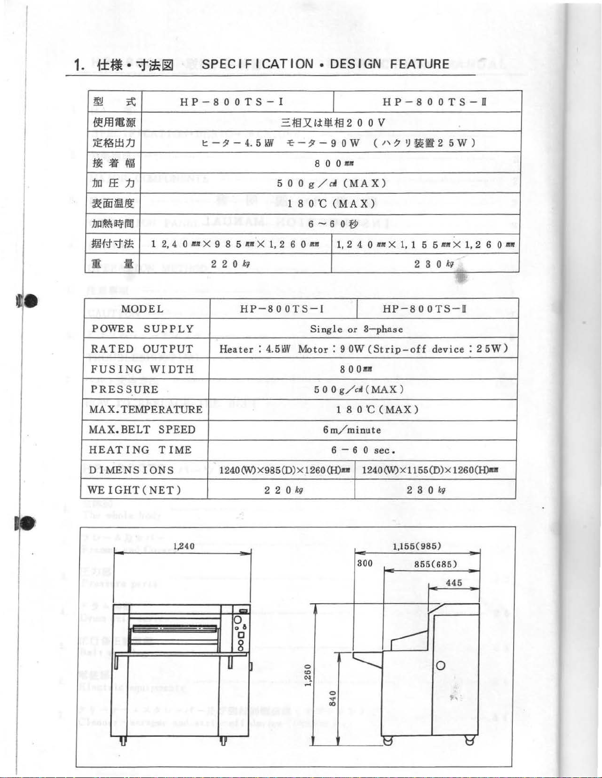
SPECIFICATION
• DESIGN FEATURE
•
1
2,
4 0
HP-800TS-I
11111
~
{~JJHIID.ii
~~WJJ
ti
:1.m
~iiiiffil.~
111l~
Wl#'f~
m
POWER
RATED
FUSING
~
!ti
~~
EE
.1J
~ey
reH
It
MODEL
SUPPLY
OUTPUT
WIDTH
t:-
~-
4.
X 9 8 5
2 2 0
111111
kg
HP-800TS-l
Heater : 4.5kW
5
WI
50 0 g/cj
X
1,
=-
m x Jj:
~-~-90W
80011/111
1 8 0
·c
6-60tp
2 6 0
111111
Single
Motor: 9 OW
I
!tHE!
(MAX)
(MAX)
1,
8 0
2 o o v
(
2 4 0
or
3-phase
Oaur
mm X 1,
(St
HP-800TS-IT
,, ? ')
HP-800TS-IT
rip
!ttl
2 5 w )
1 5 5
2 3 0
-off
device: 2 5W)
'
mm
X 1, 2 6 0
kg
111111
PRESSURE
MAX.
MAX.
HEATING
DIMENSIONS
WEIGHT(
TEMPERATURE
BELT
NET)
r
u
SPEED
TIME
1,240
124001/)X985
-
u
l
Cl
0
0 6
0
8
~
(0)X1260(H)u
2 2 0
kg
.
5 0 0
g/c~
1 8 0
6m/minute
6 - 6 0
0
~
00
(MAX
·c
1240(W)Xl155(0)X
300
(MAX)
sec.
11
.
)
2 s 0
55(985)
855(685)
~
r::::
~
1260(H)d
kg
445
0
~·
~
tp
H
t1
Page 5
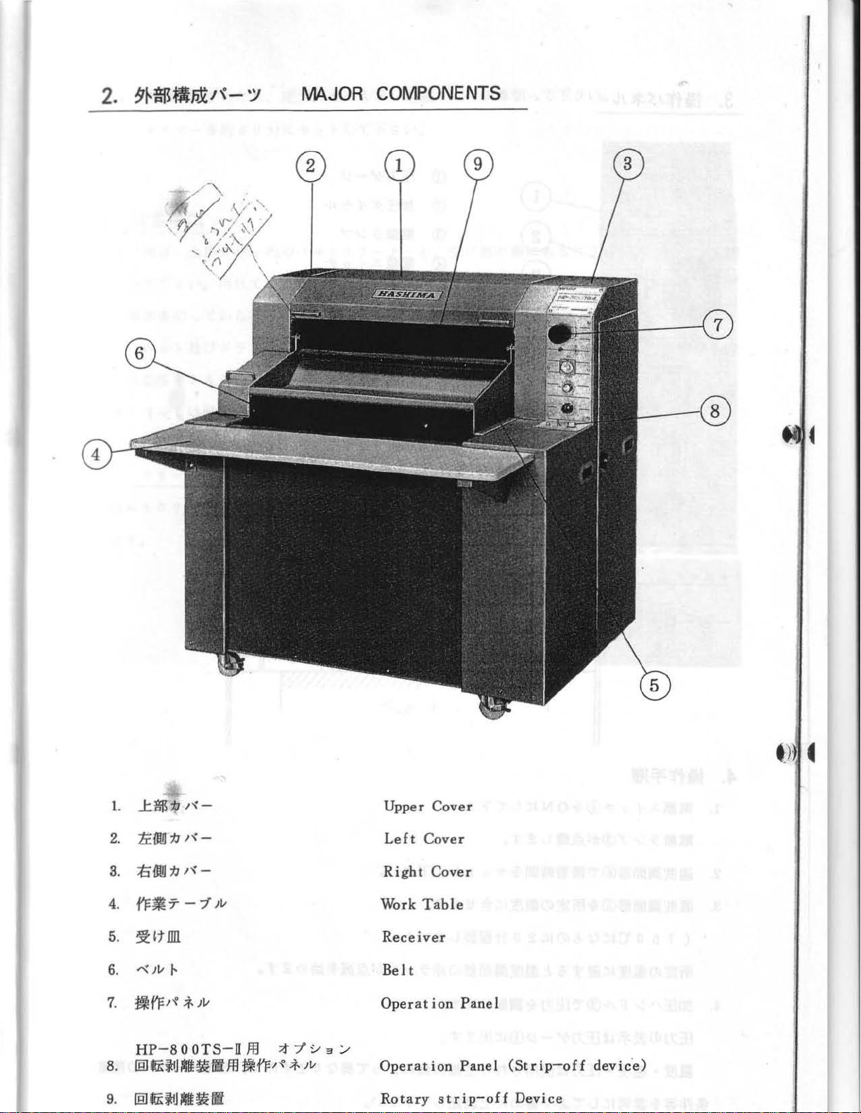
IVIAJOR
COMPONENTS
..t$
:tJ
OOJ
:fJ
Jv
fF
I'~
-8
:tJ
f-
1-{-
I~-
I "{ -
-7
Jv
;f.
Jv
0 OTS-H
::t:t~3/
Jf.l
jjfJ:I-e ;f.
Jv
Upper
Left
Right
Work
Cover
Cover
Cover
Table
Receiver
Belt
Operation
Operation
Rotary
strip-of£
Panel
Panel
(Strip-off
1.
li:OW
2.
;tj
3.
4.
fFf€7
5.
~ltnll
r{
6.
:flk
7.
HP
[ID~$fj~~fl}f.l
8.
9.
(8Jfi$1J~~ti
devic.e)
Device
Page 6
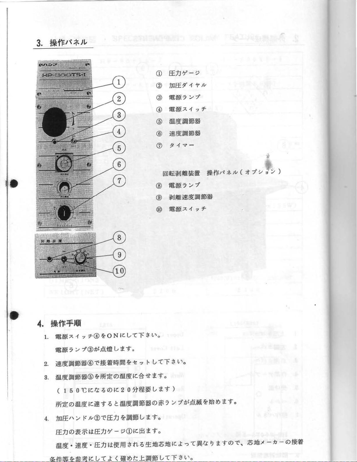
Ef.j]'T-~
<D
•
:1Jilf£~·1
®
@
t!Uili
@
Rt~7-1-:J7-
ii!ll~fP~
®
~f.!l~fm~
®
(J)
?r17
@£~J~~~~
®
falfjj7'./7'
®
idJ~~JJ}
7 './
-
~
7'
J
~fP~
@ f!Dlit7-1-:J7-
Jv
Wd'Fre
.:f
Jv
(
;t
7' :,.t
.,
'./
)
•
m~
7 './
7'®-tJ;~m.
2.
~1.11J!ilfP~®
3.
iffilf.!l~iP~®
( 1 5 o
PJT}f:O)iE!J.I
4.
:1Jilf£''/
Ef.jJO)~~UEf.;IJ'T
ii!J.I
·
~1.1
~~~
~~~K
--c:ttif~lm
~
·c
IZ:
tee
K~ T ~ t iaf.!l~fP$0)~
~Jv®I:Ef.jJ~~Wu"iTo
·
Ef.;IJii~,EH
u"l
u
~-to
PJTi.E
O)i[!J.IIZ:-ft-tt
~
0)
K 2 0
-
~<DKW~To
J: <
~~t.:l:~iP
i>
-t!
':J
"
v·cf
~To
7Nl'H~
~
tL~~:t&Z:t&IZ:.l:
u
~
T )
7
VT."""f
~
I,
"'o
:.--
7'-b;~~
~
~
lt
~~~iTo
-c~t.,c
' o
~
i
j"O)"t*
,
Z.:t&.>t
-1J-
O)~ti
Page 7
5.
fF~:6~~7
6.
~
1
";/'-
5.
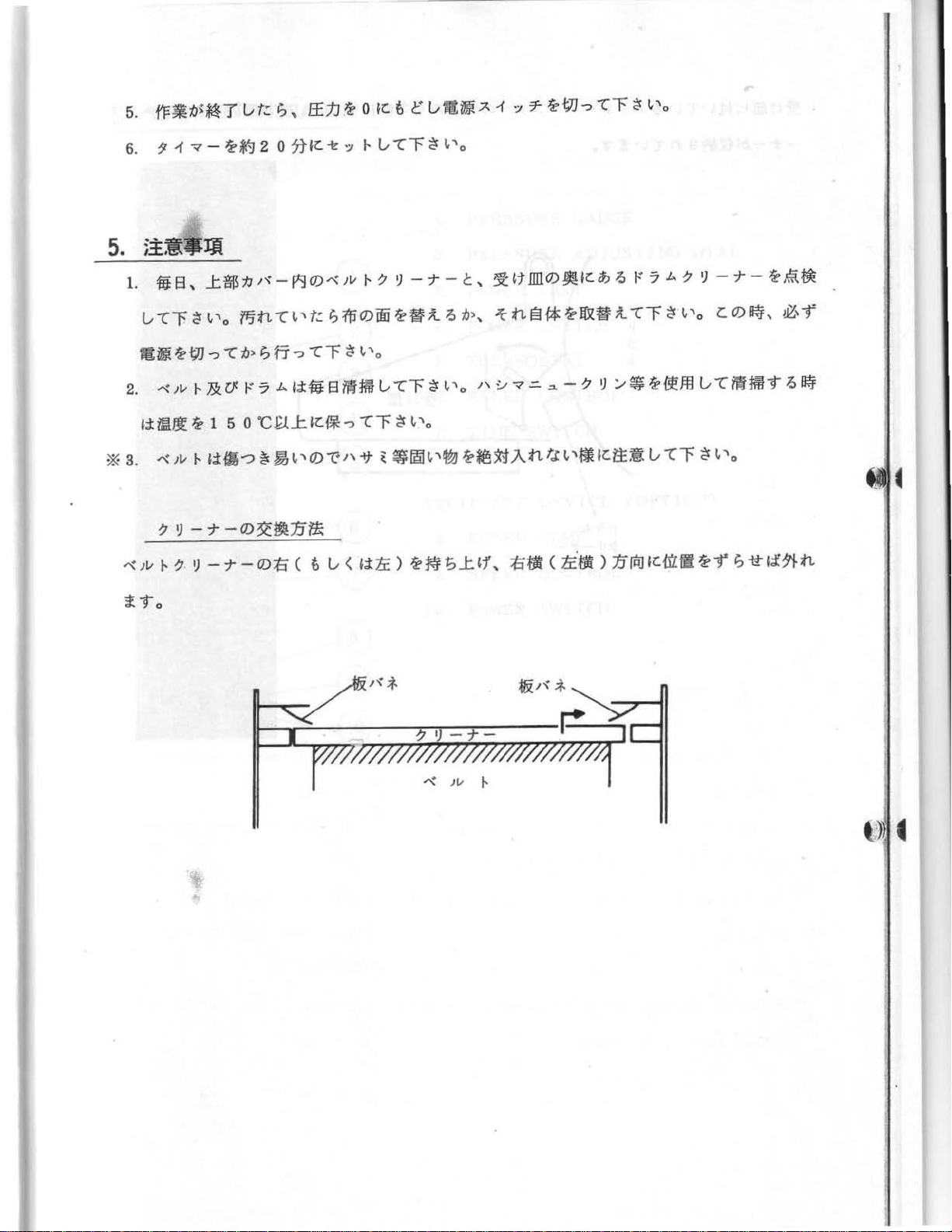
~~~-Ji
1.
fiB,
...t!lb'JI~-~0)-"\Jvl-?
vt.: ; ,.
tef-] 2 0
~t.J
teo
7JJr.-e
':1
1r.
1-
V"CF
~
c
~
--J--c,
vlttti
~
~'o
.A
1
':1
=r
-ew
-:,-·cF
~~:t.illlO)J!Kib~
~
~'o
t:7.L..?
~
--J--te,~~
l/Cf~~t'o
fi
~
te
t7J
"?
"l
2.
-"\Jvt-&rf
~j:
iAlll.l
~
1 5 0
*
s.
-"'
)v
1-
Iii~-::>~~""'
?~--j--0)~~1.11*
""')V
t-
?
~
-
-J-
1"9
0
f15tt"l~t't.:l?:(fiO)oote~il~:6>,
:6>
I?
fj
--=>
"l
r
~
It'
o
t:?
.L..~iffi8ii!t1liV"Cr~l.'o
·cf.l....t
-
OJ:ti
<
ltf*
0)
~"
t>
v <
"?
-c
r ~ (,
'o
-tt
~
~11!!1
~,
'~
lite
)
~
~-;
kttl3l*~n~il"lr~~'o
''~";/'=-
~~:X:t
...t
'1\ :tifli <
.An
.:>.
t.c
-?
~
:.--~te~ffl
1.
'~
lti:l:~
1i:.fli
)
v
1.1
rtu
~r.urm
-cr
CO)Mj,
v"lfi!imJ"t~~
~
1.
'o
~
-r
;
-tt
~,"f
1£71-
n
Page 8
•
~Jt.Dll
-
~C.fj~
'""C
-r
-
IJ>
l&kfi
~'
~
tt
.:5
-c
A?
~'
t
I"
7
J,.
v
-~~-A
"to
....---,.1
7-
0)""?
..
t h
.!l>=FiJiHC.51
I
)
~ttnn
(
c,
~
lt.Dll
O)J!•c
~
7
b.?
~
Page 9
3.
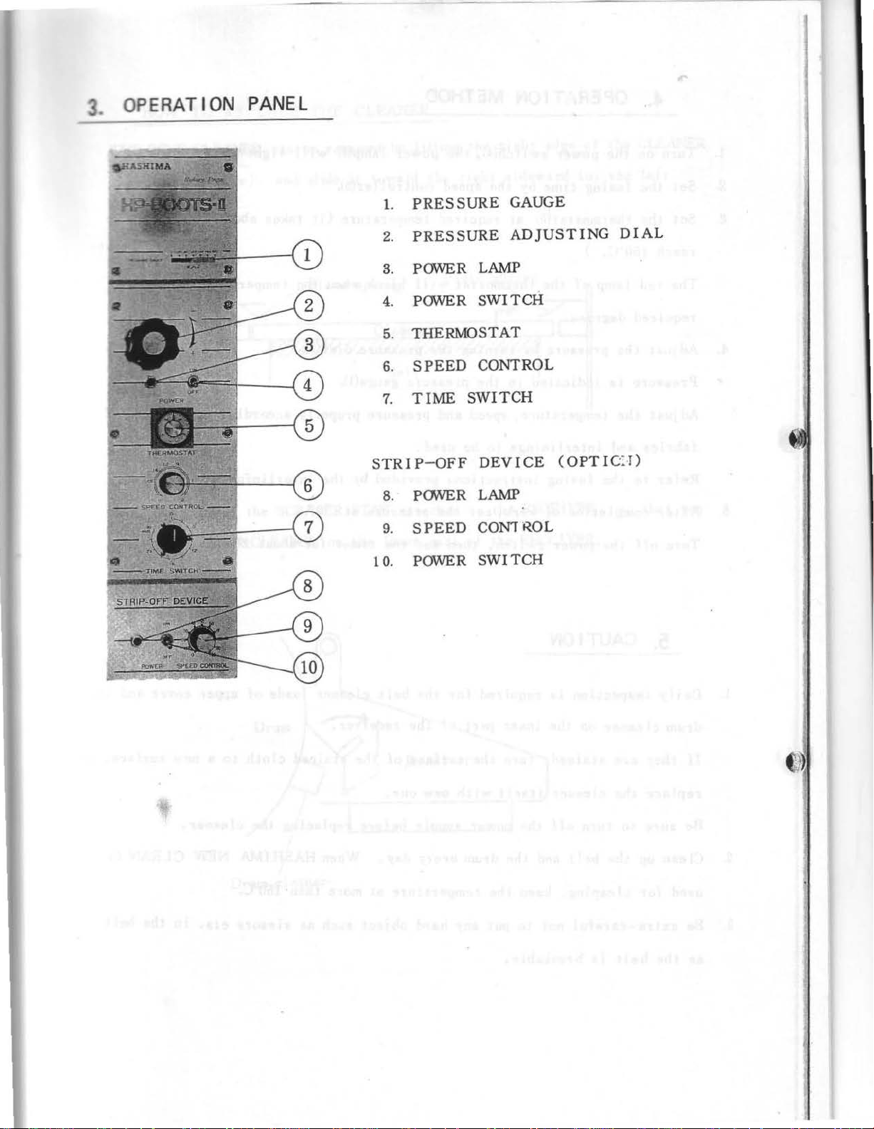
OPERAT
ION
PANEL
1.
PRESSURE
2.
PRESSURE
GAUGE
ADJUSTING
DIAL
3. POWER
4. POWER
5. THERMOSTAT
6.
SPEED
7.
TIME
S
TRIP-OFF
8. PONER
9.
SPEED
1
0.
POWER
LAMP
SWITCH
CONTROL
SWITCH
DEVICE
LAMP
CON1 ROL
SWITCH
(OPTI
C:·
T)
Page 10
1.
2.
3.
Turn
Set
Set
4.
OPERATION
on
the
power
the
fusing
the
thermostat(S)
time
swi
by
METHOD
t ch(4),
at
the
speed
required
the
power
controller(6).
temperature
lamp
(3)
will
(it
light
takes
up.
about
20
minutes
to
4.
5.
reach
The
red
required
Adjust
Pressure
Adjust
fabrics
Refer
After
Turn
off
5.
150"C. )
lamp
of
the
degrees
the
is
the
and
to
the
completion
the
.
pressure
indicated
temperature, speed
interlinings
fusing
power
CAUTION
thermostat
by
turning
in
instructions
of
work,
switch,
the
to
set
will
the
pressure
and
be
used.
provided
the
then
set
blink
pressure
gauge(l).
pressure
pressure
the
when
dial(2).
properly
by
the
at
timer
the
temperature
according
interlining
"0"
•
for
about
rises
to
manufacturer.
20
minutes:
the
to
kind
of
1.
2.
B.
Daily
drum
If
replace
Be
Clean
used
Be
as
inspection
cleaner
they
sure
up
for
extra-careful
the
belt
on
are
stained, turn
the
cleaner
to
turn
the
belt
cleaning,
is
breakable
is
the
off
and
not
required
inner
itself
the
power
the
keep
to
for
part
the
with
drum
the
temperature
put
any
.
the
of
the
surface
new
supply
every
hard
belt
receiver.
of
one.
before
day.
at
object
cleaner
the
stained
replacing
When
more than
such
insde of
cloth
the
HASHIMA
lso·c.
as
sissors
upper
to
a new
cleaner.
NEW
ets,
cover
surface,
CLEAN
1n
the
and
belt
the
or
is
Page 11
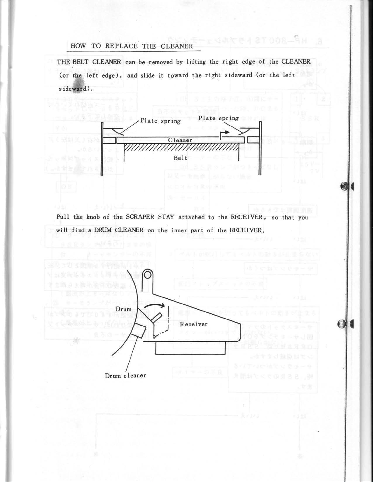
HOW
THE
BELT
(or
the
sideward).
TO
REPLACE
CLEANER
left
edge),
THE
can
be removed
and
slide
CLEANER
by
it
toward
lifting
the
the
right
rig
ht edge
sideward
of
(or
the
CLEANER
the
left
Pull
the
will
find a DRUM
knob
rff#ff$/$/;@##$#/4
of
the
SCRAPER STAY
CLEANER on
Plate
spring
Cleaner
the
Belt
attached
inner
Plate
part
to
of
spring
~
the
RECEIVER,
the
RECEIVER.
so
that
you
Drum c 1
~
eaner
..
,
I
I
)
Receiver
Page 12

6.
HP-800
TS
f-.
7-:fJt,!/
.::t
-7-
-<
/
/f
0 ffUjji A 1
mil5i
7
:--
:6>o
:;/
T
7"
:0~
~
"?
Jd1.
~
-£
-r
-r
I
1------
(,
...
(,'
~-
?1-
.At::"-t::::J/
f-c-7-0)
~B.
it
-----,---o~
J?Jj:
(
""'
~
I
if!lf~~b~3
-?:6>t.I
~j:
~ /
-tt-~.A:$1
!Elu-tt-~ 7 :--7"~0N
0 F F
:--
7"
~.isM
-tt
- ~ 7 /
~,
S S R
~
it
:;/
t.:
u
7"
0)
f-0)';17
fey,
"£
9tJ>o
;6)
"? ~ ...
7 /
~
S S R 7
-r
(,
...
7"
~i
~
~
,
.0
it
'------1
i9o
ltnr!'
-tt-
04'
..
Page 13

1 s
o·cK-tt-~A.~-:~
~
-e
-:~
t-
l/C
1:
-IT
T'IP
CD
S S R 7
.g.
-
-tt-
, 3 o
~
7 /
:f
~
7
:,;
:,;
:f
-tt-~-1!/-tj--O)~,Bt
?:Hi
J;t
~~
~
:ttJ~if!4
;O>
-::>
~-..
t-
c
u
;t
;t
t.:
;t
t.: * "1
*
0)
~:
Jj)
<D
s s R
~
7
V-
-IT-~
® S S R 7 /
--c:~tJ>..t;O~
t::-?-0)~.5!.
@ S S R 7 /
L-~;6>..!:;6~
SSRO)~,Bt
:,;
:f
7 V
A ? 7
0)
~.:r®,
;O>-::> ~ ...
;O>*
"L
f..
0)
:f
;O>~
I?
t.c ~ ...
:f;O>-::>
I?
t.c ~ ...
t.:
~,
~-..
t.c
~
~.g.
tl3-g.
®re~ur.
'1
D C
tlAi
-tt-
2.
5
&o
;t...,
Ji
t.c
u
~...,
lit.c
u
SSR7/:f
DC
2.5V-
7V
•
®
-IT-~
s
s.
ft
(
i.lill.J.l
@
-IT
~.g.
(
iAiHt
7 /
:t;O>iJlj
R 7
:..-
:t
t m
SSRO)~,Bt
;6) ..t I) ?
-
~
7 /
:f
-tj--~A?-:JI-0)~.5!.
;O>
..t
'>
-:>
Ji
;6)
'i
;t
;t
t.:
t.c
u )
-::> ~ ...
t.c
u )
t.:
* * 1:
"*
* O):ti
t.:
* *
0)
o
-~A
t.c ~ ...
'-1
? 1
-1
-:~
r
~
tJ]...,
L
~
-"'
Jv
t-
0)
ltJ
~
;6>
1.1:
*
I?
0
~-
;0>~
...
-::> * --c:
~-O)A I-':IJ'{'-;6~1/Ji;;O>f.!V'o
t tvnt.c
~
...
0
Page 14

6.
HP-SOOTS
o
Does
the
when
is
turned
the
LAMP
POWER
on ?
TROUBLESHOOTING
1 i gh t up
SWITCH
1--------,-----1
Put
the
PLUG
completely
disconnected.
in
the
if
it's being
socket
Does
the
run?
Can
the
coo
trolled
Does
the
LAMP 1
YES
DRIVING
YES
speed be
·?
THERMo-
ight
up?
MOTOR
NO----.
NO
The
MOTOR
SPEED CONTROLLER
is
defective.
or
Change
blown.
PaRER
Retur
posit ion.
the
SWITCH
NO YES
n t
he
lls:"LT
FUS E i l i t has
is
defecti~
to
.
YES
~
Does
the
SSR
when
The
the
KNOB
is
turned
1 s
turned
S S R LAMP
the
THERMO-LAMP
and
on and
I I
YES
Wi
11
the
THERMOblink
after
set
at
in
about
the
THERMOSTAT
15o·c .
NO---------.
LAMP
of
the
goes
30
blink
THERMOSTAT
THERMO-LAMP
off
?
out
when
is 1 ight
NO
LAMP
minutes
is
ing.
Check
PREVENT I
P.C.
'---
-
---t
THERMO
defective
light
is
1.
If
the
voltage
S and 4
THERMO-LAMP 1
is
2.
If
is
defective
the
SSR
set
not
.
LAMP
the BELT
0.
BOARD.
STAT
if
up wh
en
at
300'C.
betwe
en the S R
DC2.5 V
-7V
ight
s up ,
doesn' t
T SWJ
or
the
the
wh
tight
TCH
l
the ........
p.
and
.,
_..._...,.
and
the
YES
I
NO
TEMPERATURE
is
defective.
OK
3.
If
the
SSR
LAMP
doesn't rise.
doe so ' t o ff and
the
HEATER
the
Page 15

1
If
NO
the
THERMo-LAMP
*
I
doesn 1 t 1
ight,
and
the S SR
LAMP
doesn 1 t
off,
----
·- -
the
THERMO-SENSOR
2
If
the
THERMO-LAMP and
(
The
temperature
8
I£
the
THERMO-LAMP doesn 1 t
(
The
temperature
*OTHERS
When
BELT
When
The T !MER
The T !MER
the
BELTwarps,
WARPING
turning
is
doeso 1 t
doesn 1 t
STOP
of£
the
doesn 1 t
STOPPER
of£.
defective.
SSR
fall.
fal
the
BELTdoesn1t
SWITCH
POWER
1
doesn
LAMP don 1 t 1
)
of£,
THERMOSTAT
l.
)
is
SWITCH,
t
work
.
stop
defective.)
the
BELT
ight,
running.
the
is
doesn't
SSR
is
defective
J
stop
defective.
.
•
running.
1
TheTIMER
I
~
.
is
defective
. ,
Page 16

HOW
TO
REPL
?~--r
CI
eaner
ACE THE
BELT
li:
OOJ
jJ
Left
'"-
cover
..tOOJ.A?v-,-e-
Upper
~
Receiver
tt
Illl
scrape
r
Ef.t.J~r\
Pr
essure
;f.
plate
~
...tfm
b
Upper cov
'"-
er
f'F1R7
Wo
ttrr~iEo-7-
Be l t
warping
pr
evention roll
rk
-7
table
Jv
er
"'{
Jv
Bel t
J-.
7-
/
~
:r /
.A
P-t-
---
T
ension spri
7' ~ /
ng
?.
Page 17

1.
~ tt
1lll
~
2.
=f.jfflO){'F$17-7 Jv
3.
J:$::1JJ'{-
4.
~$
::1J
,'{ -
5.
""
Jv
t-
7 ~ - 7 - & U
6.
7.
8.
9.
10.
11.
12.
13.
Ef.t.Jii>
tr_t:;O)
~$
=F
tt;fjgiE
EE
fT
""1v
0
::IJ
0)
""
JW
0)
c - 7 -
t.Jtt
r\
L-
""'~
t-
b>Jf!JC"Ir.
J;t
-f
-to
~li-fT
~J;f:"fTo
~
J;t
-f
To
..1:
JC.l/t",
J'{-
Jv
c-
;f.
1i>
)v
>i>
li
f..
7
:,_.,
~
7-
li
"f
t-
Jr.1JoEE
<
1JOEE:St1
-r-t 0
~
3 /
fJ(
~rot
>i>fJt
L-
,
1JOEE
c - 7 -
;t~Hr.iE
o
001
A.
7 v -
7Jv~t;t-f"to
A.
7 I} / 7·
~
0
~rot
~0
c - 7 -
1i>
u <
~
l.t
-e
':1
rt:
-
~
!i>
li
-f
~
..1:
Jr.~
16/v
1:
7t;
t-
u-c""F ~ l.'o
Jj:
U,
-f
"G
0)
To
7 /
..t
'1
fiLflt
~
3 / c - 7 -
-c
1.;lt
~
rot
•r.
t:t:
~
~
; o
<
-e
':1
~
:f.;lt
t-
-t ; o
~
J&
~
o
14
. f.l""f,
15.
""1v
-r""f~'-'o
imO)=f.JI]liL'*fiA-L'""f~l.'o
t-
A. t:
Ct:t:£r.)
*
"")V
"li~-t~,
0
-
~
!i>-:at:it! <
xn
IJ
Mtt
u-r
;;(
1 :...-A. 1
~~~c.~mslr.t-.t~.
':1
r
...
1i>
.An,
-r~.
-r~
...
~~rr~mA.1
-rb>iE
u < fFJb-t
':1
-r
K~li>Mtt-r""F
~
b>lrt~
u
I
Page 18

7.
HOW
TO
REPLACE
THE
BELT
1. Remove
2.
Disassemble
3. Remove
4.
Remove
5.
Take
6.
Set
7.
Remove
8.
Take
9.
Pull
10.
Pull
11.
Take
it.
12.
Insert
the receiver.
the
the
off
the
the
pressure
both
off
the
out
the
out
the
off
pressure
the
pressure
the
upper
rear
belt
the
rear
front
belt
work
table.
cover.
cover.
cleaner
at
ttO",
left
belt
roller.
warping
plate spring,
roller
and
tension
and
the
prevention
the
upper
then
take
right
spring, and
and
1n a new
scraper.
off
the
covers.
roller.
pull
belt,
out
and
dial.
pull
the
the
set
tension
pressure
them
at
roller
roller
the
orig
by
out.
lif
inal
ting
.
position
18.
14.
15
.
very
carefully.
Set
the
belt
Assmbl,ing
Set
the
belt
confi
rm
whether
properly
is
to
speed
be
the
to
made
at
the
machine
be
located
following
lowest
runs
at
the
the
process
position,
properly.
center of
in
the
and
turn
the
reverse
on
the
machine.
order.
main
switch,
then
Page 19

"~
'/
1)
.A
J-.
PARTS
LIST
r
I
Page 20

Page 21

7
2
Frames
v-i.>.&fJr\-
and Cover
!
A,7
-~
I ,
I
I
I
I
L
__
_
56
3
1
•
-
6o
28
.46
Page 22

2. 7
v-
Frames
A
lk
and
U
1J
Covers
1'<-
.Jl.tfHI~
Ref
No.
1
2
3
4
5
6
7
8
9
10
11
12
13
14
15
16
17
18
19
20
21
22
28
24
25
26
27
28
.
tB
parts
..t.$tJJ~-
Upper Cover
1-
7
=F
Knob
t>.fl!-J-';11-
Hex nut
A
1-
71~-
Stopper
A
1-
';I
~~-~It
Stopper
7v-.L..J.l::.;l
Frame
lJZ~it
Plain
l~;f-~
Spring
1>.~-}-
Hex nut
!!lit*
Butterfly
-}-~tj\;j',:;
Pan
1>.~-J-71-
Hex nut
~$tJI~
Rear
-}-~!j\;f-:;
Pan screw
lq-ti
S
prin
.ijl~lt
Plain
:tiflm
Right
1j:tlJ_g
L
eft
:tiOOJ7v -.L..
Ri
ght
1i:
IJIP
Left
r-7Jv~tJ(ti)
Table
7
-7
Table
t>,~
Hex
1>.~7
Hex nut
lJZ~it
Pia
~~.::HKit
Spring washer
-}-~ !j\;j'
Pan
Jj1JOOJ
Front
sta
setting
washer
washer
7
1-
nut
screw
-
cover
g washer
wash
er
tJ
I~-
side
tJ
I~
-
side cover
side
v-.L..
side
frame
stand (R)
JII~EJ
stand
;f.
Jv
1-
bolt
7
,..
in washer
,:;
screw
tJ
I~-
s ide cover
nd
(C)
(C)
cover
frame
(1i:)
(L)
c
IIR
Name
~
(II
Q'
6 '
1
1
1
1
4
4
8
8
8
1
It
ty
til
~
Remarks
1
2
4
1
2
2
4
4
4
2
6
6
1
6
6
1
1
,
Page 23

2.
7v-.b..
F r ames and. Covers
lkU.1JJ'<-
JtW·~
Ref
No.
29
30
31
32
88
84
85
86
87
88
39
40
41
42
48
44
45
46
47
48
49
50
0
Parts
(B)
er
(B)
axis
1-
bolt
AA
Name
(A)
(B)
stay
$
7 v-Ail:;t
Frame
setting
~1f:!;f."Jv
Hex
~11:!7-:~1-
Hex nut
l~;f.ti
Spring washer
S)ll!i!~
Plain
*"".A:$1-
Caster
~1f:l,Y.
Hex
7 v - A1f:;t
Frame
~1':!:t:Jv
Hex
S)lti
Plain
l~;f.fi
Spring
~1':!7
Hex nut
7 -'\Jj\;f. y
Pan
;fJJ~-1f:;t
Cover
~1':!7-;~l-
Hex nut
"
Cover knob
t-t:•7/7
Cover knob
~11:!7\#:f-"Jv
Hex holed
::
l Al!k'¥
Ruber knob
:
:l
Ruber knob
::lAI!k'¥
Ruber knob
"
Cover
bolt
wash
Jv
bolt
bolt
washer
-;~
screw
t:•
7 /
Alik'¥
t:•
7
1-
1-
setting
1-
washer
l-
.7..7-
setting
7"
iJib
~
1'1
Q'ty
2
8
16
16
16
4
16
2
16
Hi
16
16
2
1
1
1
1
1
1
1
1
1
It
R ¥
•
Remarks
•
ll
51
52
58
54
55
56
"":1
=¥
Knob
'f::-:$1-:fJI~-
Motor
cover
~
1':!7-;~l-
Hex nut
l!m3
Butterfly
~flj;f."Jv
Hex
f'F~7-7"Jv
Work
nut
1-
bolt
table
1
1
2
2
4
1
Page 24

2. 7 v -
Frames and Covers
.b.
&
(}
1J
r\
-
R.W11~
Ref
No.
57
58
59
60
61
62
63
64
65
66
67
68
69
a
Parts
sett
>
ype D
1111
ing
Na
me
$
·~)
~nne
Receiver
'A~-J-
7 " 2
Hex nut
A~-J-7
Hex nut
A~-J-71-
Hex
l:$
Upper
Af/i-J--;~1-
Hex nut
'"*m~
Spring
~ti
Plain
-}-
Pan
~nn< 1 ~
Receiver
1-
nut
;tJ
'"
-l.l:;t
cover
washer
washer
~tJ'
'*
:.?
screw
(Ti
m:s
Magnet
Af/i;f.'JII!-
Hex
bolt
7
:/
..,
.A
J-
;t: Jv
J-
Adjusting
bolt
~
111
Q
It
't
y
1
4
2
4
4
4
4
1
2
4
4
fii
Remar ks
~
.
Page 25

,'/
//
,_
N
f
I
I
I
I
I
/
I
I
I
I
'
I
/
Page 26

3.
ff
Pressure
parts
Jut•~
Ref
No.
1
2
3
4
5
6
7
8
9
10
1l
12
13
14
15
16
17
18
19
20
21
22
23
24
25
26
27
28
Parts
c
1111
Name
$
1Jof£o
Pressure
.:f -
Key
-7-
roller
cglb-¥7-
Driving
~P:!1\f.:tl1:..>i;f-:/
Hex holed screw
-"'7
Bearing
""7
Bearing
-"'7
Bearing
~P:Jj-..,
Hex nut
SJZim~
Plain
1'\,:f-
Spring
APJ
Hex
1JDf£tJ
Pressure
\1
/?.
~
/7.t.l1
IJ
/7.tl1
washer
~~
washer
If.'
Jv
bolt
.L..i$11J
gear
r
(R)
r
(L)
C:ti>
<ro
guide
guide
"
f-
~shaft
t:"o
Pyro
AP:Jif.'
Jv
bolt
washer
~~
washer
lf.'Jv
bolt
r'J
f-
block
1-
;f-:/
screw
- .b.
;t;1
::t
warm wheel
Jv
Hex
1JDf£$7'D-:~7
Pressue
SJZfm~
Plain
r\;f.
Spring
"Pl
Hex
"Pl1\f:tl1:..>t
Hex hoI ed
1JDf£Jf.l
Pressure
~-)1.1
Seal
EftJ.Y-:/
Pressure
AP:!-T-:~1-
Hex nut
~f!J1\f:tll:..>t.:f-:/
Hex holed
1Jof£.1'H?::t-.L..
Pressure
~fijlf.'Jv
Hex
bolt
gauge
screw
warm
1-
.:¥'1'-
gear
t::"o
Pyro
EftJ'/~
Pressure
~
iflll
knob
shaft
~
•
Q'
1
8
8
8
8
1
2
4
1
8
8
2
2
1
3
2
1
2
4
2
1
1
1
1
1
1
1
1
ty
It
flti
Remarks
~
-
I
Page 27

3.
1±
Pressure
parts
J!ttHI~
R
ef
No.
-'l';r
29
30
31
82
a a
84
85
86
87
38
89
40
41
42
48
44
I
Parts
screw
c
IIR
Name
shaft
ring
/?.
spring
$
1JrJEE.I
7
Pressure
~PJ:i\f.t!l:;t.:f.~
Hex holed
~PJ7-;~t-
Hex nut
5flllilfi
Plain
1'\;f.!li~
Spring
~PJ;j{JI.I
Hex
7"/~B:,.-c-7.m
Tension
7"/
Tension
"7
Bear ing
1\.fflC~.ll:;t.
C
7"/~!1
Tension
"7
Bearing
7/~!1/jj-!~
Tension
~PJ;j{
Hex
~PJ7-;~t-
Hex
1JOEE.ffl
Pressure
knob
washer
washer
t-
bolt
roller
~;~:..-'C-7-
roller
')
:.--?·
type
retaining
/7.-f')
spring
')
'../?.
guide
)1.1
t-
bolt
nut
~I
'\;f.
plate
for
~
hole
•
O'ty
.2
4
4
4
4
1
1
1
1
2
2
2
2
2
2
2
12
til
R
emarks
~
.
Page 28

,......._._,
-:----
--
----··--
4
t'A~I
rum
axis
~
device
• • -=-
U
9
33
~
29
30
31
/ 1
. .
Page 29

4.
t-:
Drum
? .b.
axis
fiB
device
$
JHtHI~
Ref
Nn
1
2
3
4
5
6
7
8
9
10
11
12
18
14
15
16
17
18
19
20
21
22
28
24
25
26
27
28
$
Parts
Cl
AR
Name
~
(':7 A
Drum
p:]/~/ ( ~tlg
Disc
fill~/
Disc
(right)
J..l:.)l
~
setting
)
~
7
shaft
1-
lJZti
Plain
washer
l~;f&~
Spring
washer
~"1"-:~1-
Cap nut
t:7Amib.A7"c7-:~t-
D
rum
driving
l~;fti
Plain
washer
AIIJ
1t!
Jv
Hex
hoi
A1f.l;f{Jv
Hex
bolt
~IIJ-¥.Y-I::."/
Driving
sprocket
I-
t
1-
gear pin
ldb-¥.Y-
Driving
1\fflC~J..l:.)l.
C type r
1:
Heater
~71}
Bearing
~71}
Bearing
(':7 A
Drwn
lJZf!:t!:&
Plain
l~;fti
Spring
A
Hex bolt
lJZ
Plain
/
~;fti
Spring
A
Hex
-e::..-
Seoson
A
Hex
-e
S
AflJ
Hex nut
1::
H
gear
etaining ring
-~-I}
ring
::..-?·
::..-?·r,?:P/7
hous
.A
1-
stopper
washer
washer
1f.l;f{Jv
1-
ti
washer
washer
1l.!1t!Jv
1-
hoi
t
~-7-:T-
stay
1f.l;t!
Jv
1-
bolt
::..--tt-
ensor
"1"
-:~
I-
_ ,
-1.1:..)1
eat
er
setting
/If
iog
-:~If-
for
hole
.
11
O'
1
1
a
6
6
6
1
a
8
1
2
1
1
1
4
2
2
8
8
8
4
4
4
1
2
1
16
8
•
ty
titi
~
Remarks
Page 30

4. r 7 A M
Drum
axis devi
ce
iB
J!tf:HI
~
R
ef
No.
29
30
81
32
33
34
35
36
37
38
89
40
41
42
43
44
45
46
47
48
49
50
51
52
Parts
IIQ
Q
~
Name
$
t:-::11-
Heater
3Jlm~
Plain
washer
:t""{tj\ ;t,-:,/
Pan
screw
~~*''""
Hex
bolt
"E--::11-
Motor
¥7"....,"'
gear
head
~~1\#J..I:;t;f.-:,/
Hex holed screw
~l/J.A-j'0?"-:~1-
Driving
7-%.-~
Chain
sprocket
"E--::11-"{-.A
Motor
~~:T
Hex nut
~PJ
Hex nut
.iJZ~~
P
'";f.mJ?t
Sp
A~;f-'Jv
Hex
fiJI~~
Disc
Af~J;f-'Jv
Hex
/~;f.~~
Spring
.~JZmlt
Plain
7~Va~¥7f$
Tens ion
:r~v.~¥7
Ten
7-:~V;~.
Bush
SJL~~
P
C~fi!IJI'IJ.I:;t~
C type retaining ring for
lain
ring
sion
lain
base
'7
:T....,
washer
washer
bolt
(
:ttlf!IJ
( l
eft)
bolt
washer
washer
washer
"
"
1-
1-
gear
gear
)
rod
hole
.
..
It
Q'
ty
4
8
8
4
1
1
2
1
1
2
4
4
4
4
4
1
1
1
1
1
1
1
2
1
~
~
Remarks
Page 31

5 Belt
I
!Rt
~1"11~
.ii
~
warping
()
ii
tiB
prevention device
·o
•
/
•
'/
ss
I
6
so
-~
~1
12
45
54
•
l
SJ
55
22
•
.
-----
l
•
(}--~-
. ,,.,;
,
.........
' .
~
~
29
28
27
17
Page 32

5.
~
Belt
ft
warping
~
iE
~
prevention
• $
device
~tfHI~
Ref
No.
1
2
8
4
5
6
7
8
9
10
11
12
18
14
15
16
17
18
19
20
21
22
23
24
25
26
27
28
Cl
a A
Par
ts
Name
ttf!~iEJf'J
Belt
ttfi~.iEJf:I.A-1'?7-707~
Belt
?-(?c.A..f-;~7-
Micro
.i:fl~l?l
Plain
'~-*ti
Spring
1""
"';j\;t..
Pan
;..-Jt.-.1~-t:"c
Silver
warping
warping
switch
washer
washer
:;
screw
pyro
~
~
';I
"?.1
prevention
prevention
Y- 3 ' - 1 • •' - T
';I
7-"\
switch
switch
-.A
limit
base
block
tEfi$IEJf:I.A1?7-;..-•71-
Belt
warping
1:\flj
;f.'
Jv
Hex
hoi
tEfi.IEJf:l7
Belt
warp
!-
t
ing
prevention
?'-
.;t;
-1'
prevent
switch
shaft
Jv
ion ladder wheel
1:\fl:JJ\#ll:;l;f-:/
Hex
holed
screw
7?'-7-.z.-:..-
Laddr
chain
"ft;.flj
;f.'
Jv
!-
Hex
bolt
.i:flti
Plain
washer
.l~;fti
Spring
t:\fl:J7?1-
Hex nut
"f:-?-
Motor
.:¥'7"-:~,....
Gear
ljl.~~
Plain
.l~;f.ti
Spring
"ft\fl:J7?1-
Hex
1:\flj
Hex
ttfitJiEJf'J
Belt
1:\fl:JJ\#ll:.)(.::f.:/
Hex
"'"'\
Beve I
1:\fl:J/\#.Lf::;l.::f.:/
Hex
t:\flj7-;~l-
Hex
.l~;f.ti
Spring
washer
head
washer
washer
nut
;f.'
)l,f
"
hoi
t
warping
holed
Jv.:¥'7
gear
holed
nut
washer
7
9'-
prevention
screw
(A)
(A)
screw
;F
-1'
Jv
ladderwheel
•
Q
16
4
4
1
2
1
2
4
4
It
'ty
1
1
1
2
2
2
2
1
4
1
2
1
4
4
4
4
1
1
4
-~
.
Page 33

J!
W·~
Ref
29
80
81
82
88
84
86
86
87
88
89
40
41
42
48
44
45
46
47
48
49
60
6-1
62
sa
54
55
No.
5.
tE
ft
~
iE
~ il: ~
Belt w
Parts Name
r,
.i!Zm!~
Plain
washer
ten~iESW
Belt
warping
ten•IE~
Belt
...
warping
7,..
t::"D
Py
ro
_;';;
;fl,pf-'
Jt,
,..
Hex
bolt
;';;f!:l7\ft.Lt;t.::f-~
Hex holed
~~Jv-¥'7
Bevel
tl:fi.jE:fD-:~~
Belt
ten•iE:rc-:~~tJ7-
Bel t
SjZ~~
Plain
l~;:f.~~
Spring
t;;f!:J
;f.'
Hex bolt
D-7-7-:~~
Roller
screw
(B)
gear
(B)
warping prevention
warping
washer
Jv
prevention
washer
1-
hook
lJZti
Plain
washer
~~.:t-El~
Spring
;';;f!:l
Hex
MjitJc
Sub
t;;f!:J:f.'Jv
Hex
lJZfl~
Plain
~~.:t-m~
Spring
;';;f!:l7-:~,..
Hex
J\
Hanger
D-7/\'./tj-
Roller
311
Split
flfjfltJD-7
Sub
~7 ~ './~
Bearing
fl!lfflC~lt;t~
C type
'./
IJ
;f.'
bolt
nut
tJ.
t:"
roller
washer
Jv
J-
bolt
-7
fill
roller
1-
washer
washer
-
t:"
'./
pin
hanger
'./
pin
'
retaining
(B)
shaft
arpin
Cl
AA
provention
proven
tion
(B)
ring for hole
g pr
stand
shaft
block
block
eventio
collar
n de
il
Q'ty
2
2
2
2
2
2
1
2
2
2
2
1
1
1
2
2
vice
li
4
1
1
2
4
2
1
1
2
2
56
Page 34

1t~~~
6
Electric equipments
0
.·
49
I
8
7
7
27
_
_j
..
27
13
·.
Page 35

6.
~
E
lectric
equipments
JUf.Hl~
R
ef
No.
~ -,.1
1
2
3
4
5
6
7
8
9
10
11
12
18
14.
15
16
17
18
19
20
21
22
~a
24
25
26
27
28
$
j--"{Jj\.;f. y
Pan
screw
Sfl~il
Plain
washer
::l
;f. ? ? - (
Connector
1<;.~7
';I
washer
Jll
bolt
O.A-1
washer
;f.m.il
screw
1-
washer
1-
switch
washer
board
Hex nut
J'{.;f.~il
Spring
Sfll!l!il
Plain
t<;.~,Y.
Hex
!J~-:~l-.A-1-:~7-f!'rl#.A7-
Limit
7-1?
Micro-switch
iJlfiil
Plain
J'{
Spring
j--"{Jj\.;f.y
Pan
12-~
Wiring
Q
IIA
Parts
(for Strip-of£
Name
18Jtii$1J~~t:iffl
setting
":1
T
~
)
device)
stay
EEJJit
Pressure
E£t.J"
Pressure
-~7:.--7'
Power lamp
ti~.A-177'-
Power
i!i&li®H
Thermostat
18Jti$1Jft~flf.ffHI~
Power
18Jti$1J
Power
-At:"-rf.W®lf."!J::t..
Speed
A
1::"-
Speed
?-17-
Timer
?-17-Jf.l'/7~
Time
!ID
tiJ!.LW~f!m.A
Speed
,Y.!).,.-A
Volume
.AI::"-r::J:.--J-o-7
Speed control l
~Ti3
Terminal
gauge
:.--
r
111
handle
switch
7
:.--
lamp
for
ft~IIJIIlt~.A
switch
for
7'
Strip-off
-1
-;~
Strip-off
device
7-
- A
control
rMro·.:~
control
r knob
control
...
frame
volume
~
knob
~::·-
r~ro·.:~7
knob
for
Strip-off
er
device
~
device
111
Q
.4
It
'ty
4
4
1
4
4
4
4
2
2
4
4
1
1
1
1
1
1
1
1
1
1
1
1
1
1
1
1
tit;
¥
Remarks
Page 36

6.
~
Ele
ctric
equipments
J!tt:\-~
Ref
No.
29
30
31
32
33
34
35
36
37
38
89
40
41
42
43
44
45
46
47
48
49
50
51
52
$
:J/r/-ttCondenser
:J/7/-if
Condenser
l-7/.7..
Transformer
~-Ttj'
Terminal
t:
"" -;(
;t.
Fuse holder
t:
::>.
Fuse
'J
~
Solid
:J/7/-if-
Condenser
:f')/)-J$;Uj
P.
:f!)
Connector
,q;;r..?-
Varis.tor
SSR7/:f
SSR
,.-e;f.Jv
Panel
Jv
-.7..-
? r
.7..
7 -
state
C.
board
/ "~~~ :J
'lamp
(A)
(A)
Parts
-I&tt:fv
setting
frame
~·-
I-
relay
for
P.C.B
a
All
Name
-1-
plate
!)
v-
;f,? ~ -
~
( S. S. R )
41
O'
ti
Washer
A
-tt7'J';f.
Flush
,.-e;f.Jv
Panel
,-e;f,Jv
Panel
l~;f-~~
Spring
.ill~~
Plain
"f;;,f/iJ"f"?l-
Hex nut
"''-';f.
Hex
7v-t.J-
Breaker
7
?•;t.?
Magnet
@~~~~~~;;r..~-r:J/!-o-7-
Speed
:/
screw
(B)
(B)
(C)
(C)
washer
washer
Jv
)-
bolt
"
controller
for
Strip-off
device
2
2
10
10
4
4
ty
1
1
1
1
1
2
1
1
1
2
l
1
1
4
4
1
l
1
~
tit;
Remarks
¥
-
..
.
Page 37

J
'J
--t--·
7 Cleaner·
;zJ
scraper
v-/{-&lflill-'.£i<U~~m:(~7·~
and
strip-off
device (Option)
3
/)
(·
.. d
l
4
~
l
10
Page 38

7. ?
1
J
--r-,
Cleaner•scraptu
.A?
and
v
-1'\-h?:OIEJti~J~fUitl:
strip-off
device
(Option)
(
;t7
•:Y
3 '../ )
JUfHI-it
Ref
No.
1
2
a
4
5
6
7
8
9
10
11
fB
1'\jlj ;f.' )1/
Hex
~7-:~1-
Cap out
:A?
Scraper
~
S i I icon
1'\jlj ;f.' )1/
Hex
J
'\;f.~
Spring
3JZ~~
Plain
?
Cleaner guide
?
Clea.
~)1/"
Belt
1'\jlj ;f.'
Hex
1-
bolt
v
-J\'-~f1
holder
!J
::J
/:A?
scraper
1-
bolt
l'fl
washer
washer
!)
-7-ff1
!)
-
7-J'\-
ner
bar
)I/
1-
bolt
Parts
v-1\'-
~
(
(for
Cl
AA
~
)1/
Belt)
Name
1-Jf.l)
~
(I
Q'ty
~
til
Remarks
~
2
2
1
1
8
8
8
2
1
I
m!
1
• Type I
nm! • Type
n
2450D
2750U
4
18
14
15
16
17
18
19
20
21
22
28
24
25
26
27
28
12
'"*~~
Spring
3JZ~~
Plain
¥7"'-:~r
Gear head
(Ub:A:;fa7?1-
Driving
7'\jlj/\#Ll:;t.:f.~
H
(igltJ:A:fo7::~1-
Driving
7'\jlj/\#Ll:;t;f.~
Hex holed
~.fillLI:;t7-:~l-
Receiver
~f*,Y.
Special
1'\1IJ7?1-
Hex out
?1)-7-1'\-(
Cleaner
7'\jlj;f-';1/
Hex
'"*~~
Spring
ex
washer
holed
)1/
bolt
washer
washer
sprocket
screw
sprocket
screw
setting
1-
bolt
bar
(for
1-
nut
1'7A.If.l)
Dram)
.lJZti
Plain
washer
rB.Jfij!Jim";.f-:flfl;t
Strip-off
rB.JtijfJ~"
Strip-off-
liD
fij!J~Uil
Strip-off
- Blade holder
_;f,
Blade
axis
4
4
1
1
2
1
2
1
2
1
1
12
12
12
4
4
1
Page 39

].
'J
Cleaner•scrap
I)
-_1"- , A
'J
v
e r
and strip-off
-1~-}.k{}@fi:ljij·~~
de
vice (Opt
ion
(
)
:t7·~
3 / )
Ju
t•~
Ref
No.
29
BO
81
82
88
84
85
86
81
88
19
40
~·
u
Pa
rts
a
IIA
Name
$
311
!>
t:"
/
Split
pin
7-\f'J
;f,'
'"'
Hex
7-.z.-/
Ch
:c-~-..-{-;;r.
Mot
7-\f'J;f,'
Hex
:c-~-
Motor
;;r.-7
Scraper
;;r.-7
Scraper
T->ft!-T-:~1-
H
ex
.I~'*
Spring
1-
bolt
ain
or
base
'"'"
bolt
v-1-f-
V-1'{'-~'1
holder
nut
lli!:i?i
washer
.l!llm:i?l
Plain
washer
7-\f'J;f,'
Jll
1-
Hex
bolt
''Jv
~
Knob
:c-~-;f,',?;;r.
Motor box
~
•
Q'
1
2
.4
4
2
2
l
It
ty
2
1
1
1
2
1
1
til
Remark
~
s
.
 Loading...