

Hasco Z 12402 Operating Instructions Manual
GB 12/13 HK
Operating Instructions
Z 12402 /. . .
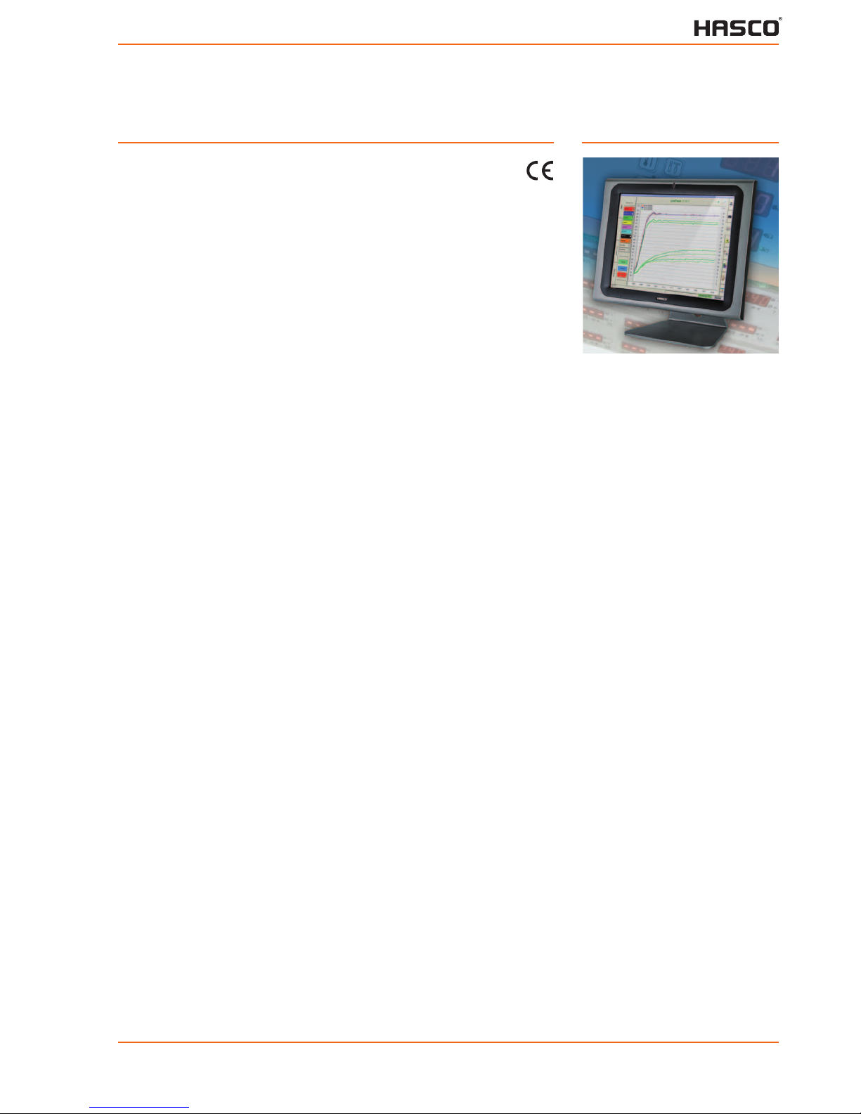
Process monitor

Content
1 General 4
1.1 Safety attention 4
1.2 Start 4
1.2.1 Online – Offline 4
1.3 Operation elements 4
1.3.1 Operation of the controller 4
1.4 Description of features 4
2 Operation of the connected MCS-controllers 5
2.1 Password 5
2.2 Snapper 6
2.3 Headline 6
2.4 Indication 6
2.4.1 Total 6
2.4.2 Detail 7
2.4.3 Groups assortment 7
2.5 Tool 8
2.6 Trends 8
2.6.1 Filter 9
2.6.2 History / Live 9
2.6.3 Power and energy 9
2.6.4 Scaling 10
2.7 Alarms and reports 10
2.7.1 System reports 10
2.7.2
Fault statistics 11
2.8 Settings for the zones 11
2.8.1
Z 1240 Z 1246 series 11
2.8.2 Zone-parameters 12
2.8.3 Global Parameters 12
2.8.4 Recipes 12
2.9 Groups 13
2.9.1 Rename zone 14
2.10 Wiring Check 14
2.10.1 Protocols 14
3 Commissioning 15
3.1 Mount the monitor 15
3.2 Connection 15
3.3 Settings 15
3.3.1 Clock 16
3.3.2 Program settings – MCS Control 16
3.3.3 RS485 – Interface input 17
3.3.4 RS485 – Interface- output 17
3.3.5 RS485 – Interface-transmission 17
3.3.6 RS485 – Online / Offline 17
3.3.7 Tool-Selection 18
3.3.8 Groups-Settings 19
3.3.9 Diagnosis-Settings 19
3.3.10 Boost-Settings 19
3.3.11 Printer-Settings 20
3.3.12
Login 20
3.3.13 Diagram-Settings 21
3.3.14 Memory 21
2

4 Tool Setup 22
4.1 End of setup 23
4.2 View 23
4.3 New Touch-section 23
4.4 New value: actual, setpoint, output rate or current 23
4.4.1 Indicate title 23
4.4.2 Move 23
4.4.3 Change 23
4.4.4 Copy size 23
4.4.5 Alignment 24
4.5 Delete 24
5 Technical data 25
5.1 User level 25
5.1.1 Service 25
5.1.2 Configuration 25
5.1.3 Tuning 26
5.1.4 Operation 26
5.1.5 Indication 26
5.2 Index 27
3

1 General
The monitor Z 12402 is designed for comfortable operator interface with data storage and
diagnosis.
1.1 Safety attention
The monitor Z 12402 will be powered by the low voltage net. The local and general instructions have to be observed for the installation and operation.
The supply voltage and frequency must correspond to the data on the label!
The maker and seller of the units are not responsible for direct or indirect damages due to
incorrect operation.
Disconnect the
Z 12402 from the supply net before open the cover!
Assembly, connections and basic settings
will be described in the chapter commissioning.
1.2 Start
The ON/OFF-switch is to reach from the rear side on the bottom beside the entry of the power cable.
1.2.1 Online – Offline
The linked controllers are indicated after the start. As far as these are not equal to the last
operation or the addresses do not begin with No.1, a newly search or the offline mode may
be selected.
(see Commissioning / Connection and Interface)
1.3 Operation elements
The monitor is fit with a touch-screen. All available keys on the screen are able to react after
touch.
Activated functions are labelled with bold fonts or shown by “pressed” buttons. Lightly shown
buttons are not available.
1.3.1 Operation of the controller
All controllers may be operated, even when the monitor is connected. The respectively last
operation is valid.
1.4 Description of features
This manual bases on the complete manual for hotrunner controllers. These functions and
terms will not be explained in the following.
4
2 Operation of the connected Z 1240 / 1246
The operation of the controllers happens by the different zones. These may be collected in
groups or operated separately. The control units itself will not appear in the structure of
Z 12402.
Different functions are available at the right hand side or directly by additional menus.
A selection referring to the indications is available on the left hand side.
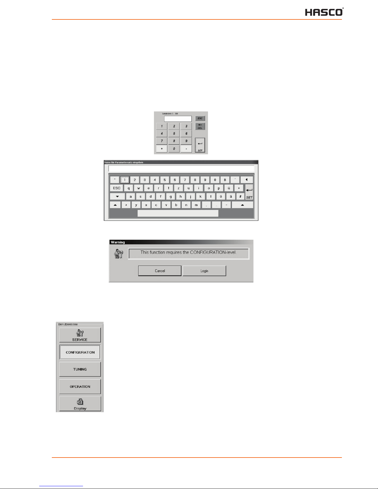
Settings have to be done by adapted keyboards, which will be presented when required.
Numeric
keyboard
Complete
keyboard
Opened hints indicate warnings or operator actions with required decisions.
2.1 Password
The user levels correspond to 0..3 of the Z 1240 / 46. (for functions see Technical Data)
Z 12402 Default -locking / Default-password
“Service”
Level 3 Password ”22“
Level 2 Password “22“
Level 1 Without password, not locked
Level 0 Without password, not locked
The password may be changed during commissioning in the menu Login.
5
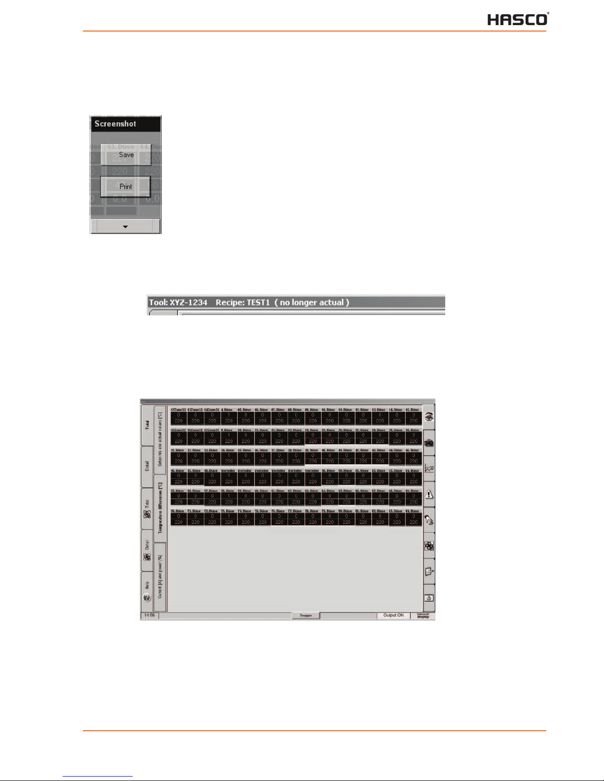
2.2 Snapper
This button takes screenshots / hardcopies.
Stores the actual picture in an external
memory.
Prints the actual picture by a connected
printer.
Escape
2.3 Headline
The headline represents the name of the actual tool and recipes with current relevance.
2.4 Indication
The control zones may be indicated by Total, Detail or the single zone.
2.4.1 Total
Zones
Zones
Total
Tool-Image
Zones
Detailed
Trends
Alarms
Reports
Total
Assorted
Input
Detailed
Assorted
Groups
Diagnosis
Help Commissioning
Screenshot Report Status Level
The total overview allows an indication of actual value, setpoint, difference, output rate or
current. This may be selected on the left hand side.
Alarms will be flashing with the referring zone.
The touch on a zone opens the screen of a single zone.
6
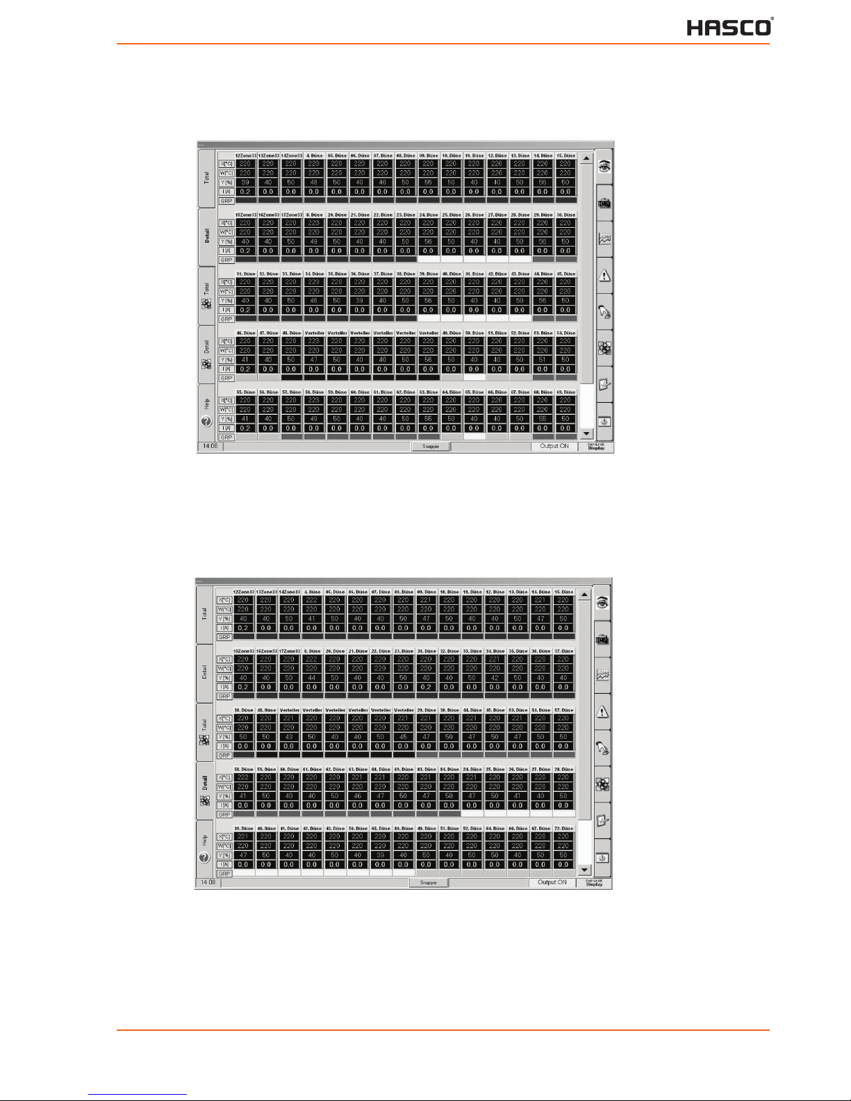
2.4.2 Detail
Zones
Zones
Total
Tool-Image
Zones
Detailed
Trends
Alarms
Reports
Total
Assorted
Input
Detailed
Assorted
Groups
Diagnosis
Help Commissioning
Screenshot Report Status Level
The shifter on the left hand side chooses the selection.
The touch on a zone opens the screen of a single zone.
The touch on the colour of a group opens the screen of the zones of this group.
2.4.3 Groups assortment
Zones
Zones
Total
Tool-Image
Zones
Detailed
Trends
Alarms
Reports
Total
Assorted
Input
Detailed
Assorted
Groups
Diagnosis
Help Commissioning
Screenshot Report Status Level
The buttons on the left side also enable an assortment of the groups. The sequence refers to
the setting of the groups.
The touch on a zone opens the screen of a single zone.
The touch on the colour of a group opens the screen of the zones of this group.
7
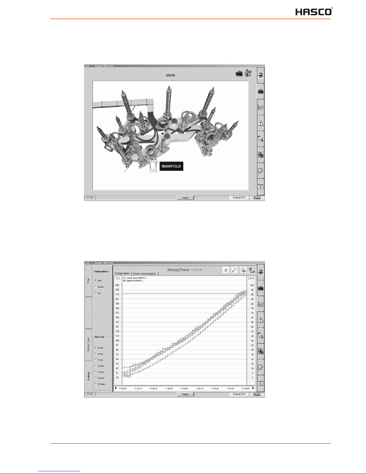
2.5 Tool
Main
picture
Setup
Zones
Tool-Image
Trends
Alarms
Reports
Input
Groups
Diagnosis
Commissioning
Screenshot Report Status Level
The assembly of a tool will be described in the chapter Tool Setup. The functions of the tool
illustration depend on the referring design.
2.6 Trends
Curves
Power
bars
Zones
Filter Tool-Image
Trends
Alarms
Reports
History /
Live
Input
Groups
Scaling Diagnosis
Commissioning
Screenshot Report Status Level
The signification of the curves may be indicated by a touch and the moving of the magnifier.
8
2.6.1 Filter
The filter enables a collection of zones for the trend-curves. Different groups, an individual
selection of zones and zones without group are available. Actual values, setpoints and output
rates are available for this collection by a touch.
The colours refer to the legend in the upper section.
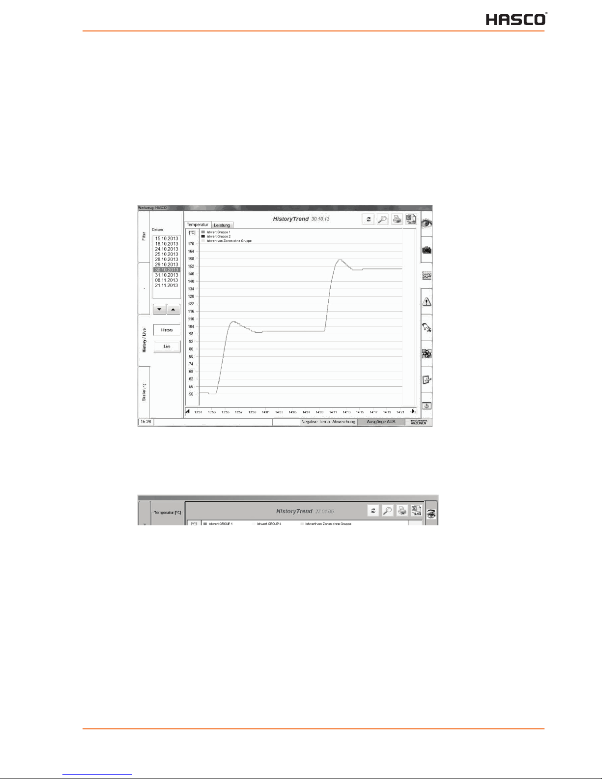
2.6.2 History / Live
The illustration of actual or historical data may be selected by this screen or in the headline.
The referring date has to be selected for historical curves.
Zones
Filter Tool-Image
Trends
Alarms
Reports
History /
Live
Input
Groups
Scaling Diagnosis
Commissioning
Live/Hist.
Magnifier
Print
Export
• The magnifier may be moved to identify the curves.
• The data of the selected historical diagram may be exported to an Excel file. The re-
ferring file name will b e in dicated.
• The actual diagram may be printed by an installed printer.
9
 Loading...