


Version/Warranty/Return &
Repair/Copyright
Version Information
Version number: a
Version date: December 1, 2017
Warranty Period
SMART antenna host: 1 year
Cables and other accessories: 90 days
Return & Repair
Please contact us if you need to return the product to our factory for
repair.
Copyright Information
All the software involved in this document is protected by Harxon
Corporation (hereinafter referred to as "Harxon"), and all rights are
reserved. All rights concerning this document, including the copyrights,
are exclusively owned by Harxon. This document shall not be duplicated
in any means such as printing, copying, and recording without prior
consent of the copyright owner.
Disclaimer
Every effort has been made in the preparation of this document to
ensure accuracy and integrity of the contents, but Harxon shall not be
liable for any possible errors or omissions herein. Harxon may change
the technical specifications or functions of its products along with
2 / 75

continuous development of technologies without notifying users in
writing.
3 / 75

Contents
Version/Warranty/Return & Repair/Copyright ..................................................................... 2
Warranty Period .................................................................................................................... 2
Return & Repair .................................................................................................................... 2
Copyright Information ........................................................................................................ 2
Disclaimer ............................................................................................................................... 2
Contents ......................................................................................................................................... 4
List of Figures ................................................................................................................................ 7
List of Tables .................................................................................................................................. 9
Precautions .................................................................................................................................. 11
FCC Caution ......................................................................................................................... 11
§ 15.19 Labeling requirements. ....................................................................................... 11
§ 15.105 Information to the user. ................................................................................... 11
§ 15.21 Information to user. ............................................................................................ 12
Symbol Conventions ......................................................................................................... 12
Product Certification Information ................................................................................. 12
Acronyms and Abbreviations (A–Z)............................................................................... 13
User Service ................................................................................................................................. 15
Frequently-Asked Questions (FAQs) ............................................................................. 15
Recording Information...................................................................................................... 15
Contact Us ............................................................................................................................ 15
1 Overview ................................................................................................................................... 16
1.1 Product Features .......................................................................................................... 16
1.2 Conventions .................................................................................................................. 17
2 Assembly and Installation .................................................................................................... 18
2.1 Required Accessories.................................................................................................. 18
2.2 Required Extra Devices (from the User) ................................................................ 18
2.3 Product Assembly ....................................................................................................... 18
2.3.1 Assembling the SMART Antenna Rover ..................................................... 18
2.3.2 Power Supply Requirements ......................................................................... 20
2.3.3 Installing the SMART Antenna ...................................................................... 21
2.4 Other Information About the SMART Antenna ................................................... 22
2.4.1 Status Indication ............................................................................................... 23
2.4.2 Assembling the Built-in Radio ...................................................................... 23
2.4.3 Assembling the Bluetooth Module ............................................................. 24
2.4.4 Assembling the Network Module ................................................................ 24
2.4.5 Assembling the CAN Module ....................................................................... 24
4 / 75

2.4.6 Assembling the Tilt Module .......................................................................... 24
2.5 Assembling the External Radio
............................................................................ 25
2.5.1 Installing the External Radio ......................................................................... 25
2.5.2 Power Supply Requirements ......................................................................... 27
2.6 Assembling the Rover Kit (with External Radio)
2.7 Assembling the Rover Kit (with Built-in Radio)
.............................................. 27
................................................ 28
3 Operation Instructions .......................................................................................................... 30
3.1 Configuring the Rover Host...................................................................................... 30
3.1.1 Serial Port Default Configuration ................................................................ 31
3.1.2 Querying Host Parameters of the SMART Antenna Rover .................... 31
3.1.3 Configuring Host Parameters of the SMART Antenna Rover ............... 32
3.2 Configuring the External Radio ............................................................................... 33
3.3 Configuring the Built-in Radio ................................................................................. 35
3.3.1 Powering on the Built-In Radio .................................................................... 36
3.3.2 Querying or Configuring the Parameters of the Built-In Radio .......... 36
3.4 Configuring the Bluetooth Module ........................................................................ 37
3.4.1 Configuring the Parameters of the Bluetooth Module .......................... 38
3.4.2 Monitoring the SMART Antenna Through the Bluetooth Module ..... 39
3.5 Configuring the Network Module .......................................................................... 39
3.5.1 Configuring the Network Operator ............................................................ 40
3.5.2 Configuring the Network Service Parameters .......................................... 41
3.6 Calibrate Tilt .................................................................................................................. 42
3.7 Setting Up the Rover .................................................................................................. 43
3.7.1 Setting Up the Rover Kit (with Built-in Radio) .......................................... 43
3.7.2 Setting Up the Rover Kit (with External Radio) ........................................ 44
3.7.3 Precautions on Rover Setup .......................................................................... 45
3.8 Firmware Update ......................................................................................................... 46
3.8.1 Firmware Update for the SMART Antenna Host ...................................... 46
3.8.2 Firmware Update for the Built-in Radio ..................................................... 47
3.8.3 Firmware Update for the External Radio.................................................... 49
3.8.4 Firmware Update for the CAN Module ...................................................... 49
3.7.5 Firmware Update for the GNSS Module .................................................... 50
Appendix A Technical Specifications .................................................................................... 51
A.1 Specifications of the SMART Antenna Rover ...................................................... 51
A.2 Specifications of the Radios ..................................................................................... 53
A.2.1 Specifications of the External Radio (HX-DU1601D) ............................. 53
A.2.2 Specifications of the Built-in Radio (HX-DU1006D) ............................... 54
A.3 Specifications of the Bluetooth Module ............................................................... 54
5 / 75

A.4 Specifications of the Network Module ................................................................. 55
A.5 Specifications of the Tilt Module ............................................................................ 55
A.6 Accessories of the SMART Antenna Kit ................................................................. 56
A.6.1 Data Cable (HJ681) .......................................................................................... 56
A.6.2 SMART Antenna Configuration Cable (HJ568) (Optional) .................... 57
A.6.3 Configuration Cable of the External Radio (HJ394) (Optional) ........... 59
A.6.4 Power Cable (HJ379) ....................................................................................... 61
Appendix B Commands ............................................................................................................ 62
Appendix C Output Protocols ................................................................................................. 64
C.1 NMEA0183 .................................................................................................................... 64
C.1.1 GGA Positioning Result .................................................................................. 64
C.1.2 GSA Satellite PRN Data .................................................................................. 66
C.1.3 GSV Satellite Status Data ............................................................................... 66
C.1.4 RMC Data ........................................................................................................... 67
C.1.5 ZDA Time Data ................................................................................................. 68
C.1.6 PSAT Attitude Data .......................................................................................... 69
C.2 NMEA2000 .................................................................................................................... 70
Appendix D Substitution Components ................................................................................ 71
D.1 SMART Antenna Rover Host .................................................................................... 71
D.2 Accessories of the SMART Antenna Rover .......................................................... 71
Appendix E SMART Antenna FAQs ........................................................................................ 73
LED Exceptions .................................................................................................................... 73
6 / 75

List of Figures
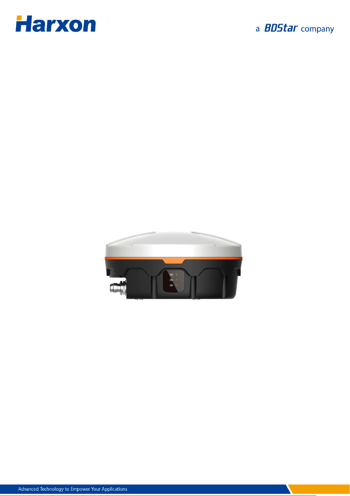
Figure 1 SMART Antenna ................................................................................................. 16
Figure 2 SMART Antenna Data Interface ..................................................................... 19
Figure 3 Assembly Diagram of the SMART Antenna Rover Host .......................... 20
Figure 4 Magnetic Adsorption
Figure 5 Installation with 5/8-Inch Screws .................................................................. 22
Figure 6 Installation with M4 Screws ............................................................................ 22
Figure 7 Attitude Angle Coordinate System of the SMART Antenna Rover ....... 25
Figure 8 Data Interface of the External Radio ............................................................ 25
Figure 9 Assembly Diagram of the External Radio.................................................... 26
Figure 10 Assembly Diagram of the SMART Antenna Rover Kit (with External
Radio) ............................................................................................................................ 27
Figure 11 Assembly Diagram of the SMART Antenna Rover Kit (with Built-in
.................................................................................... 21
Radio) ............................................................................................................................ 29
Figure 12 Main Window of the SMART Antenna Configuration Tools ................ 32
Figure 13 Configuration Tools — GNSS Settings ...................................................... 33
Figure 14 Software Window for Querying/Configuring the Parameters of the
External Radio ............................................................................................................. 35
Figure 15 Software Window for Querying/Configuring the Parameters of the
Built-in Radio ............................................................................................................... 37
Figure 16 Bluetooth Module Configuration Window .............................................. 38
Figure 17 Network Module Configuration Window ................................................. 40
Figure 18 Tilt Calibration Window ................................................................................. 43
Figure 19 Connecting the Port for the Host Firmware Update ............................. 46
Figure 20 Starting the Host Firmware Update ........................................................... 47
Figure 21 Connecting the Port for the Firmware Update for the Built-in Radio
......................................................................................................................................... 48
Figure 22 Starting the Firmware Update for the Built-in Radio ............................. 48
Figure 23 Starting the Firmware Update for the External Radio ........................... 49
Figure 24 Firmware Update for the CAN Module ..................................................... 50
Figure 25 SMART Antenna Host Dimensions ............................................................. 52
Figure 26 Structural Size of the Data Cable (HJ681) ................................................. 56
Figure 27 Welding Surface at Port C of the Data Cable (HJ681) ........................... 56
Figure 28 Welding Surface at Port B of the Data Cable (HJ681) ........................... 56
Figure 29 Structural Size of the SMART Antenna Configuration Cable (HJ568)57
Figure 30 Welding Surface at Port A of the Configuration Cable (HJ568) ......... 58
Figure 31 Welding Surface at Port B of the Configuration Cable (HJ568) ......... 58
7 / 75

Figure 32 Structural Size of the Configuration Cable of the External Radio
(HJ394) .......................................................................................................................... 59
Figure 33 Welding Surface at Port C of the Configuration Cable (HJ394) ......... 60
Figure 34 Welding Surface at Port B of the Configuration Cable (HJ394) ......... 60
Figure 35 Structural Size of the Power Cable (HJ379) .............................................. 61
8 / 75

List of Tables
Table 1 Meanings of Symbols in This Manual ............................................................ 12
Table 2 Certifications that the Product Has Passed .................................................. 12
Table 3 Definition of the SMART Antenna Data Interface ....................................... 19
Table 4 List of Components of the SMART Antenna Rover Host .......................... 20
Table 5 Definitions of the LEDs ....................................................................................... 23
Table 6 Definition of the Data Interface of the External Radio .............................. 26
Table 7 List of Components of the External Radio .................................................... 26
Table 8 List of Components of the SMART Antenna Rover Kit (with External
Radio) ............................................................................................................................ 28
Table 9 List of Components of the SMART Antenna Rover Kit (with Built-in Radio)
......................................................................................................................................... 29
Table 10 Specifications of the SMART Antenna Rover ............................................. 51
Table 11 Specifications of the External Radio (HX-DU1601D) ............................... 53
Table 12 Specifications of the Built-In Radio (HX-DU1006D)................................. 54
Table 13 Specifications of the Bluetooth Module ..................................................... 54
Table 14 Specifications of the Network Module
.................................................... 55
Table 15 Specifications of the Tilt Module .................................................................. 55
Table 16 List of Components of the Data Cable (HJ681) ......................................... 56
Table 17 List of Components of the SMART Antenna Configuration Cable
(HJ568) .......................................................................................................................... 57
Table 18 Pinouts of Port A of the Configuration Cable (HJ568)
......................... 58
Table 19 List of Components of the Configuration Cable of the External Radio
(HJ394) .......................................................................................................................... 59
Table 20 Pinouts of Port B of the Configuration Cable (HJ394)
......................... 60
Table 21 List of Components of the Power Cable (HJ379) ...................................... 61
Table 22 Syntaxes of SMART Antenna Commands ................................................... 62
Table 23 List of SMART Antenna Firmware Update Commands ........................... 62
Table 24 List of NMEA0183 Output Protocols ............................................................ 64
Table 25 GGA Positioning Result ................................................................................... 64
Table 26 GSA Satellite PRN Data .................................................................................... 66
Table 27 GSV Satellite Status Data ................................................................................ 66
Table 28 RMC Data ............................................................................................................ 67
Table 29 ZDA Time Data ................................................................................................... 68
Table 30 PSAT Attitude Angle Data ............................................................................... 69
Table 31 List of NMEA2000 Output Protocols ............................................................ 70
Table 32 List of Optional Hosts for the SMART Antenna Rover ............................ 71
9 / 75

Table 33 List of Optional Accessories for the SMART Antenna Rover ................. 71
10 / 75

Precautions
FCC Caution
§ 15.19 Labeling requirements.
This device complies with part 15 of the FCC Rules. Operation is subject
to the following two conditions: (1) This device may not cause harmful
interference, and (2) this device must accept any interference received,
including interference that may cause undesired operation.
§ 15.105 Information to the user.
Note: This equipment has been tested and found to comply with the
limits for a Class B digital device, pursuant to part 15 of the FCC Rules.
These limits are designed to provide reasonable protection against
harmful interference in a residential installation. This equipment
generates uses and can radiate radio frequency energy and, if not
installed and used in accordance with the instructions, may cause
harmful interference to radio communications. However, there is no
guarantee that interference will not occur in a particular installation. If
this equipment does cause harmful interference to radio or television
reception, which can be determined by turning the equipment off and
on, the user is encouraged to try to correct the interference by one or
more of the following measures:
-Reorient or relocate the receiving antenna.
-Increase the separation between the equipment and receiver.
-Connect the equipment into an outlet on a circuit different from that
to which the receiver is connected.
-Consult the dealer or an experienced radio/TV technician for help.
11 / 75

Symbol
Description
Remarks
Indicates that a note exists
for this indicator or item on
this page.
If multiple notes exist on a page,
the number inside the symbol will
increase accordingly.
Indicates some matters that
deserve users' attention.
Standard
Remarks
FCC
Rules and Regulations: FCC Part 15B
CE
RED Article 3.2 Radio
RED Article 3.1(b) EMC
RED Article 3.1(a) Safety
RED Article 3.1(a) Health
§ 15.21 Information to user.
Any Changes or modifications not expressly approved by the party
responsible for compliance could void the user's authority to operate the
equipment.
This equipment complies with FCC radiation exposure limits set forth for
an uncontrolled environment. This equipment should be installed and
operated with minimum distance 20cm between the radiator & your
body.
Symbol Conventions
Table 1 Meanings of Symbols in This Manual
Product Certification Information
Table 2 Certifications that the Product Has Passed
12 / 75

RoHS
RoHS Directive 2011/65/EU and its amendment directives – XRF
screening test and Wet Chemical Testing (Lead, Cadmium,
Mercury, Hexavalent Chromium, PBBs & PBDEs content)
REACH
One hundred and seventy three (173) substances in the Candidate
List of Substances of Very High Concern (SVHC) for authorization
published by European Chemicals Agency (ECHA) on and before
January 12, 2017 regarding Regulation (EC) No 1907/2006
concerning the REACH
IP67
Acronyms and Abbreviations (A–Z)
APN Access Point Name
ASCII American Standard Code for Information Interchange
BT Bluetooth
CMR Compact Measurement Record
COG Course Over Ground
DOP Dilution of Precision
GAGAN GPS Aided GEO Augmented Navigation
GGA Global Positioning System Fix Data. Time, Position and fix related data for
a GPS receiver
GLONASS GLObal NAvigation Satellite System
GNSS Global Navigation Satellite System
GPS Global Positioning System
GSA GPS DOP and active satellites
GSV Satellites in view
IP Internet Protocol
MSAS Multi-Functional Satellite Augmentation System
NMEA National Marine Electronics Association
NTRIP Networked Transport of RTCM via Internet Protocol
RMC Recommended Minimum Navigation Information
RTCM Radio Technical Commission for Maritime Services
13 / 75

RTK Real Time Kinematic
SBAS Satellite-Based Augmentation System
SOG Speed Over Ground
UTC Coordinated Universal Time
WAAS Wide Area Augmentation System
ZDA Time & Date – UTC, Day, Month, Year and Local Time Zone
14 / 75

User Service
Frequently-Asked Questions (FAQs)
For technical problems, please refer to the section SMART Antenna FAQs,
which describes the symptoms and causes of some common problems
and corresponding solutions.
Recording Information
If you cannot find any record about your technical problem in this
manual, please record relevant information, such as the operating
environments before and after the problem occurred, operation steps,
symptoms, as well as the product model, hardware version number, and
firmware version number.
The product model, hardware version number, and firmware version
number information can be queried by using the SMART Antenna
Configuration Tools.
Contact Us
Please contact us for more help and support.
Service hotline : +86-755-26989948 (8:30-12:00 & 13:30-18:00)
Sales hotline : +86-755-86578389 (8:30-12:00 & 13:30-18:00)
Fax : +86-755-26989994
Email : sales@harxon.com
15 / 75
1 Overview
The SMART antenna rover is a high-performance GNSS receiver. With a
built-in all-band antenna and a high-accuracy GNSS board, the SMART
antenna rover can simultaneously track GPS, BDS, and GLONASS signals
and supports up to 192 channels. In addition, it provides various
functions such as the 3G/4G module (optional), radio module (built-in or
external), CAN module (optional), and Bluetooth module (optional). The
SMART antenna rover has three LEDs to indicate its own working status.
It supports multiple protocols such as RTCM and CMR for differential
data reception. The radio module is compatible with mainstream
vendors' transmission protocols.
Figure 1 SMART Antenna
1.1 Product Features
The SMART antenna rover has the following functional features:
High-performance GNSS board capable of simultaneously tracing
GPS L1/L2, BDS B1, and GLONSS L1/L2 signals
High-performance GNSS all-band antenna
One RS232 port
One CAN port
16 / 75

Bluetooth module
3G/4G module
Built-in/external radio
Three status LEDs
IP67 protection
Three installation modes: magnet, 5/8-inch screws, or M4 screws
Note:
This component is optional.
1.2 Conventions
The following conventions apply in this document:
The characters following 0x are a hexadecimal number.
Sent commands are case-sensitive characters.
17 / 75

2 Assembly and Installation
2.1 Required Accessories
External radio
Antenna of the external radio
Wire bundle for connection between the SMART antenna and the
external radio (Data cable)
Wire bundle for connection between the SMART antenna rover and
the computer (SMART antenna configuration cable)
Wire bundle for connection between the external radio and the
computer (Configuration cable of the external radio)
2.2 Required Extra Devices (from the User)
Computer
Power supply (to supply power to the SMART antenna or the external
radio)
2.3 Product Assembly
2.3.1 Assembling the SMART Antenna Rover
1. Connect the SMART antenna configuration cable to the rover. Figure
2 shows the data interface of the SMART antenna rover. Table 3
defines the data interface of the SMART antenna rover.
18 / 75
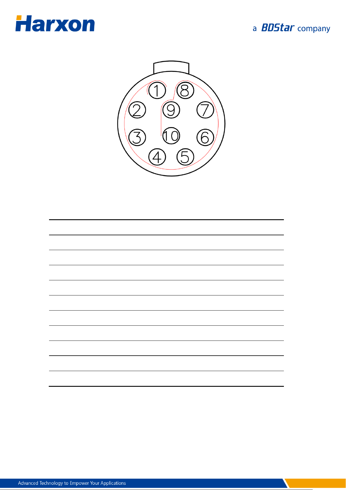
Pin
Name
Description
Remarks
1
TXD1
Output
RS232
2
RXD1
Input
RS232
3
NC
Output
4 VCC
Power supply
DC 9 V to 30 V
5
GND
Ground
6 NC
Reserved
7 NC
Reserved
8 NC
Reserved
9 CANH
High-level input/output
10
CANL
Low-level input/output
Figure 2 SMART Antenna Data Interface
Table 3 Definition of the SMART Antenna Data Interface
2. Connect the SMART antenna configuration cable to the DB9 serial
port on the computer.
3. Connect the SMART antenna configuration cable to the power cable.
19 / 75
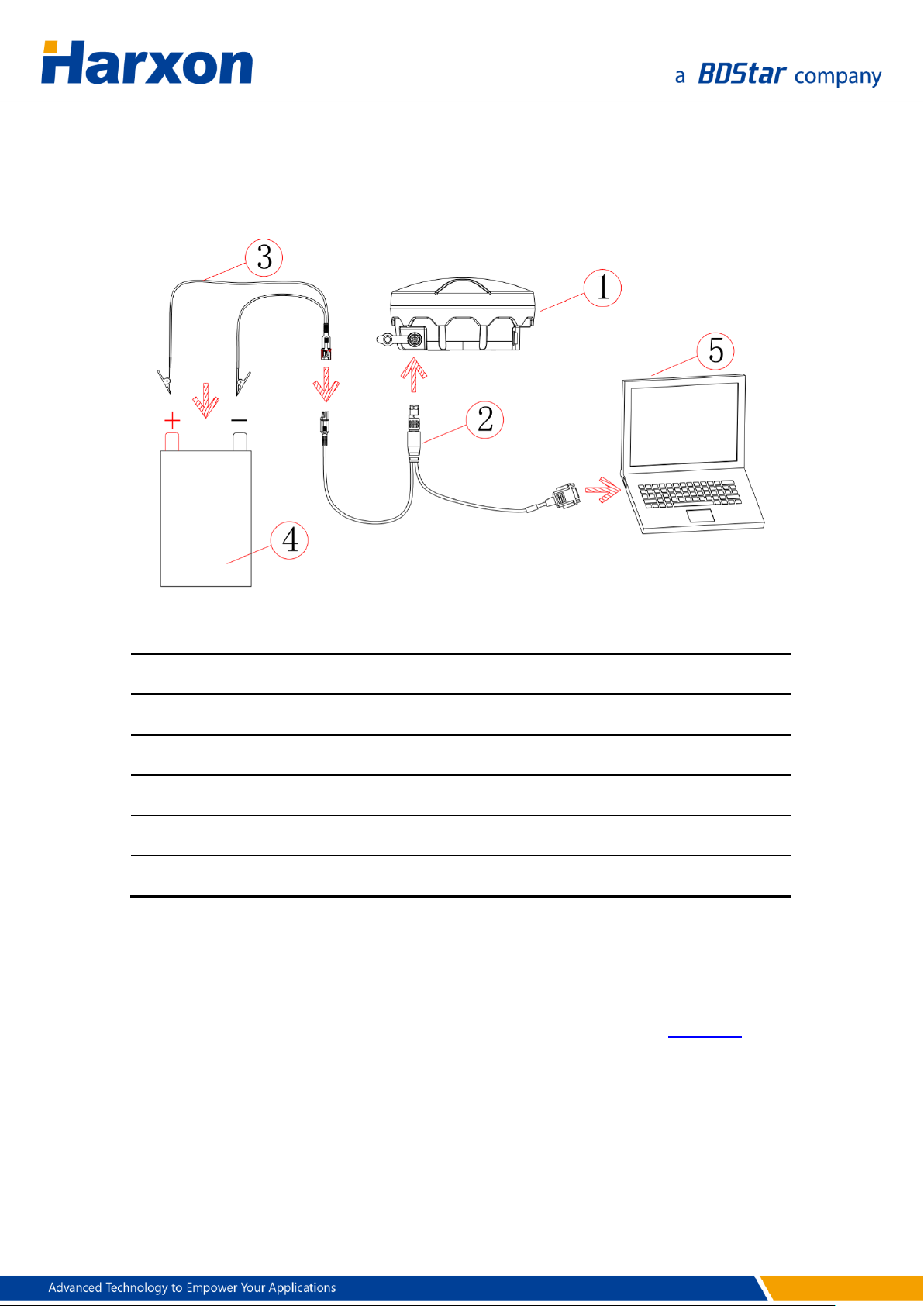
Reference No.
Description
Model
1
SMART antenna rover
All model
2
SMART antenna configuration cable
HJ568
3
Power cable
HJ379
4
Power supply
To be provided by the user
5
Computer
To be provided by the user
Switch on the power supply. The power LED on the SMART antenna
rover will be steady on.
Figure 3 Assembly Diagram of the SMART Antenna Rover Host
Table 4 List of Components of the SMART Antenna Rover Host
2.3.2 Power Supply Requirements
The input voltage of the SMART antenna rover should be DC 9 V to 30 V.
For details about the other power supply requirements, see Table 10. The
power cable of Harxon SMART antenna has alligator clips at one end to
directly bite the positive and negative poles of the power supply.
20 / 75
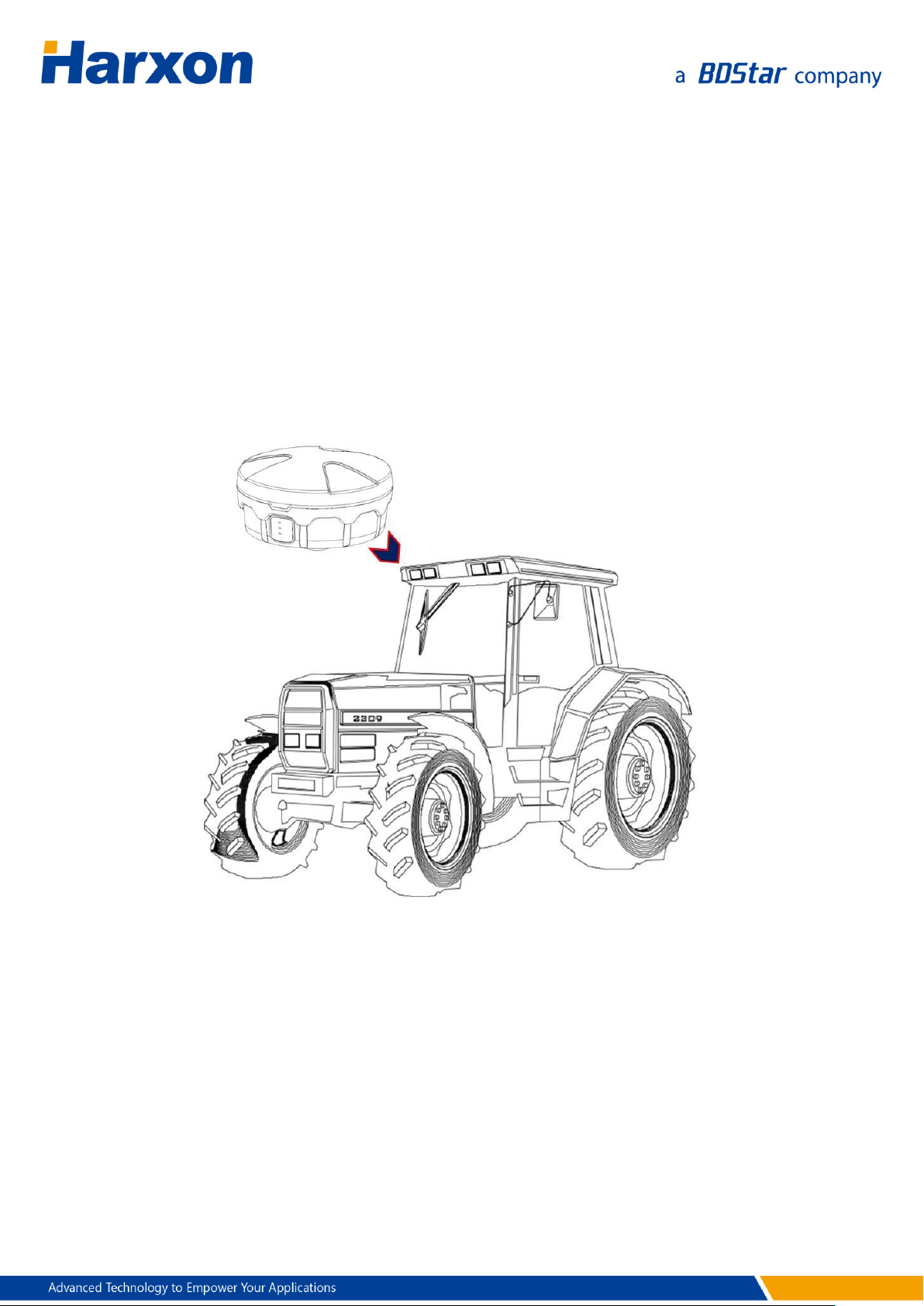
2.3.3 Installing the SMART Antenna
You need to install the SMART antenna in a safe, stable, and open
environment. The SMART antenna supports three installation modes:
Magnet
5/8-inch screws
M4 screws
Figure 4 Magnetic Adsorption
Note:
The installation mode shown in the schematic diagram merely expresses the
magnetic adsorption manner. The SMART antenna is not necessarily installed
on a tractor.
21 / 75
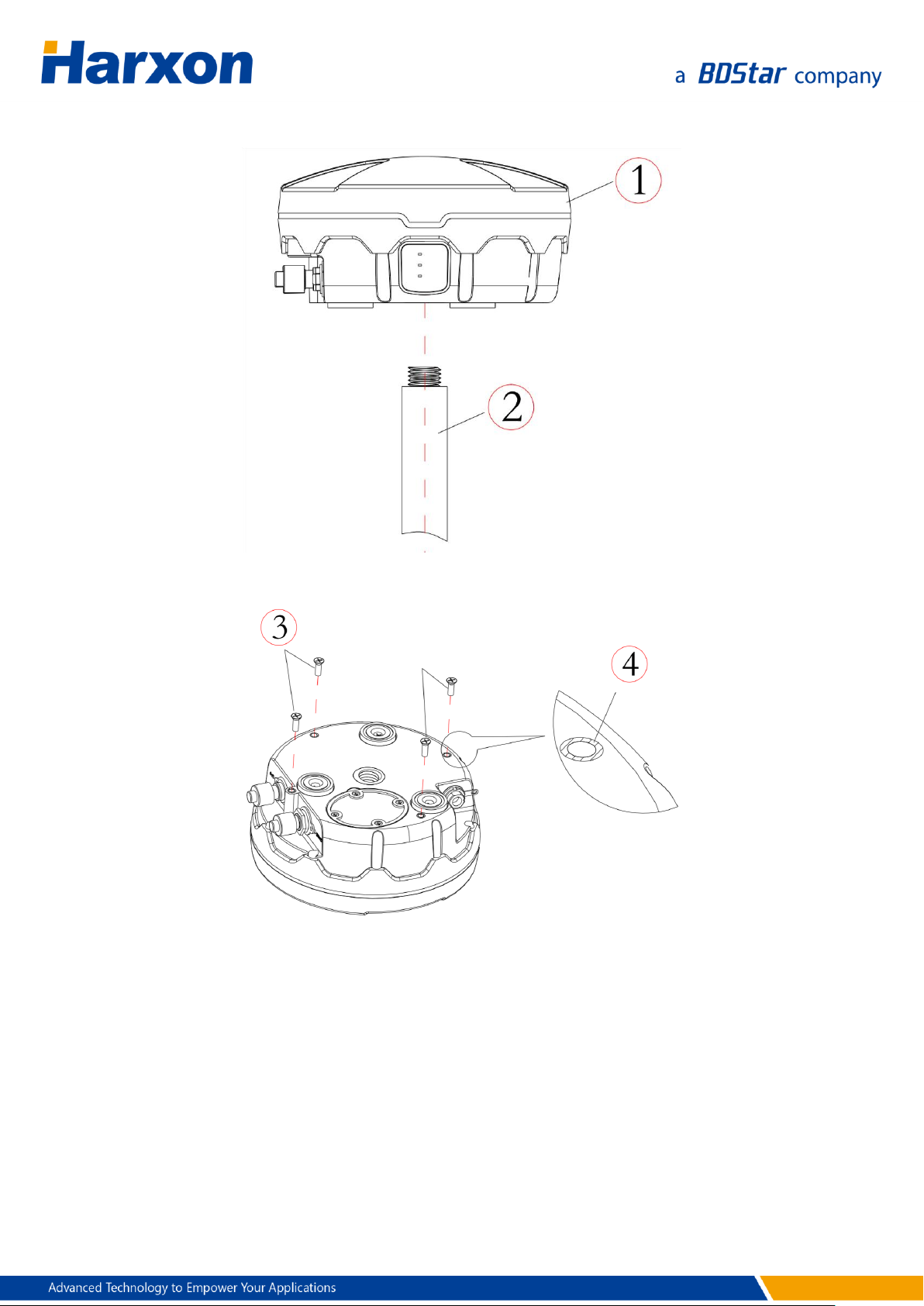
Figure 5 Installation with 5/8-Inch Screws
Figure 6 Installation with M4 Screws
2.4 Other Information About the SMART Antenna
This section describes some other information about the SMART antenna
rover to help you properly use the SMART antenna rover.
22 / 75
PWR
(Red)
SAT
(Green)
LINK
(Green)
Meaning
OFF
--
--
The power supply is unavailable.
ON
OFF
--
The power supply is available, but
single-point positioning fails.
ON
Blinking
--
The power supply is available. The blinking
times represent the number of satellites
used for the positioning.
ON
Blinking (G1)
-> ON ->
Blinking (G2)
--
The power supply is available. The status
ON between the two sets of blinking
indicates that the rover is already in fixed
status.
ON
Blinking (G1)
-> OFF ->
Blinking (G2)
--
The power supply is available. The status
OFF between the two sets of blinking
indicates that the rover is not yet in fixed
status.
ON
--
Blinking
The power supply is available, and data is
being received on the differential data
serial port.
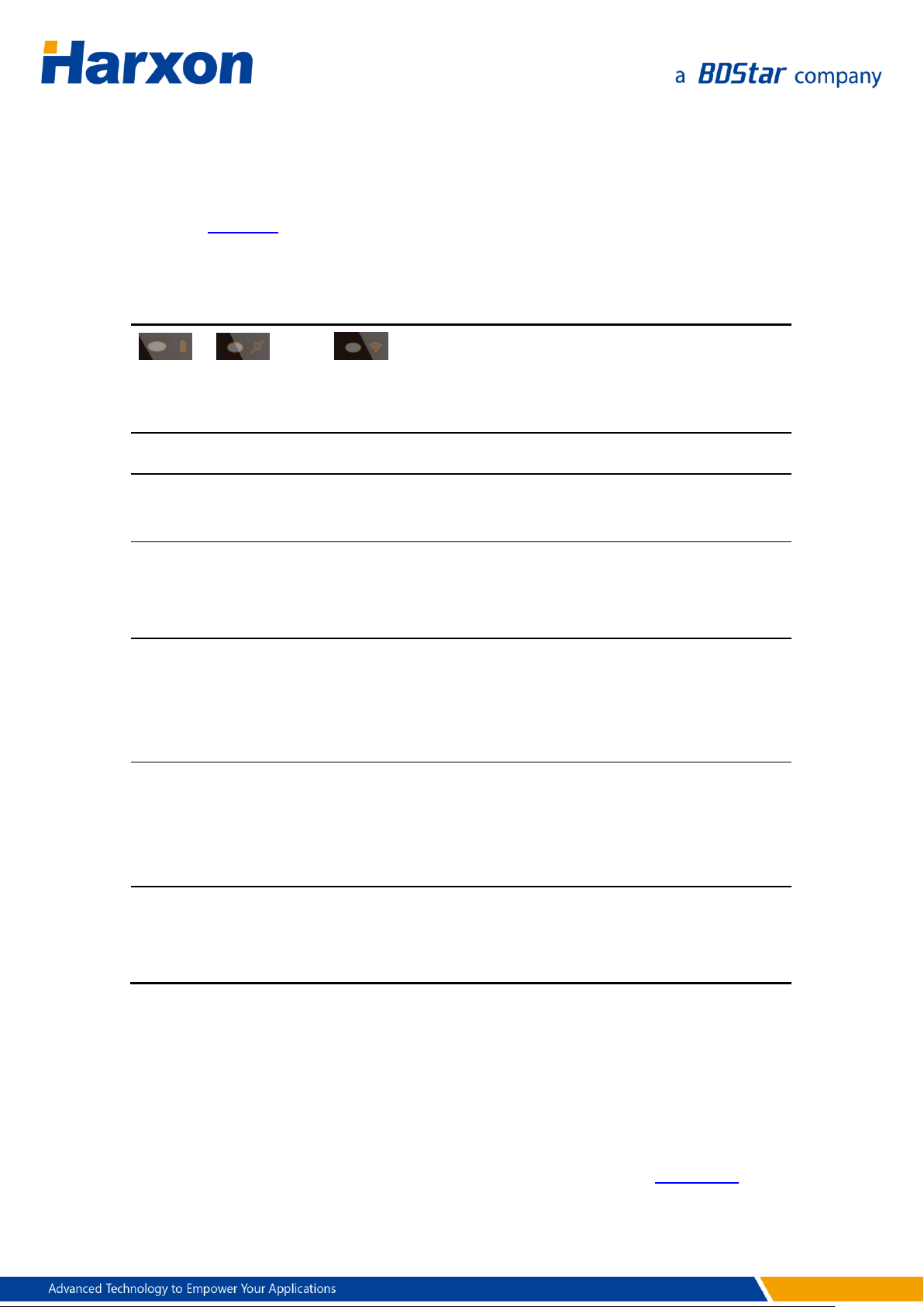
2.4.1 Status Indication
The SMART antenna provides three LEDs to indicate its own working
status. Table 5 describes the meanings of the LEDs on the SMART
antenna.
Table 5 Definitions of the LEDs
2.4.2 Assembling the Built-in Radio
Note:
If the product you select has the built-in radio, you need to assemble
only the antenna of the radio using the method shown in Figure 11.
23 / 75

2.4.3 Assembling the Bluetooth Module
Note:
You do not need to assemble the Bluetooth module of the product.
2.4.4 Assembling the Network Module
Note:
You do not need to assemble the network module of the product.
2.4.5 Assembling the CAN Module
Note:
You do not need to assemble the CAN module of the product.
2.4.6 Assembling the Tilt Module
Note:
You do not need to assemble the tilt module of the product, but should
pay attention to the coordinate axis direction of the tilt module during
the installation and setup of the SMART antenna rover.
Figure 7 shows the attitude angle coordinate system of the SMART
antenna rover. Attitude angle information is output through the PSAT
statements of the National Marine Electronics Association (NMEA)
protocol. When the SMART antenna is horizontally placed, the X axis
points to the LEDs on the SMART antenna, the Z axis points to the
antenna top, and the Y axis points to a direction according to the
right-hand screw rule. Figure 7 shows the attitude angle coordinate
system of the SMART antenna rover with the tilt module.
24 / 75

X
Y
P
H
R
Z
Figure 7 Attitude Angle Coordinate System of the SMART Antenna Rover
H : Heading, R : Roll, P : Pitch,
2.5 Assembling the External Radio
Note:
Read this section if the product you select has the external radio; otherwise,
simply skip this section.
2.5.1 Installing the External Radio
1. Connect the configuration cable of the external radio to the external
radio. Figure 8 shows the data interface of the external radio. Table 6
defines the data interface of the external radio.
Figure 8 Data Interface of the External Radio
25 / 75

Pin
Name
Description
Remarks
1
VCC
Power supply
DC 9 V to 16 V
2
PGND
Power ground
3
TXD
Output
RS232
4
GND
Signal ground
5 RXD
Input
RS232
Reference No.
Description
Model
1
External radio
HX-DU1601
2
Configuration cable of the external
HJ394
Table 6 Definition of the Data Interface of the External Radio
2. Connect the configuration cable of the external radio to the DB9
serial port on the computer.
3. Connect the configuration cable of the external radio to the power
supply cable. Switch on the power supply. The power LED on the
external radio will be steady on.
Figure 9 Assembly Diagram of the External Radio
Table 7 List of Components of the External Radio
26 / 75

radio
3
Power cable
HJ379
4
Power supply
To be provided by the user
5
Computer
To be provided by the user
2.5.2 Power Supply Requirements
The input voltage of the external radio should be DC 9 V to 16 V. For
details about the other power supply requirements, see Table 11. The
power cable of the Harxon external radio has alligator clips at one end to
directly bite the positive and negative poles of the power supply.
2.6 Assembling the Rover Kit (with External Radio)
Note:
Read this section if the product you select has the external radio; otherwise,
simply skip this section.
Figure 10 Assembly Diagram of the SMART Antenna Rover Kit (with External Radio)
27 / 75

Reference No.
Description
Model
1
SMART antenna rover
Host non build-in radio
2
External radio
HX-DU1601
3
Antenna of the radio
QC400SI
4
Data cable
HJ681
5
Power cable
HJ379
6
Power supply
To be provided by the user
Table 8 List of Components of the SMART Antenna Rover Kit (with External Radio)
Install the antenna of the radio at a relatively high position, so that
the radio can better receive differential data broadcast by the base,
making possible a longer distance between the rover and the base.
The input voltage of the SMART antenna rover kit should be DC 9V to
16V.
2.7 Assembling the Rover Kit (with Built-in Radio)
Note:
Please contact us if you want to select other built-in radios.
The antenna you select for the radio must match the radio. Please contact us if
you want to select other antennas for the radio.
Read this section if the rover kit you select has the built-in radio; otherwise,
simply skip this section.
28 / 75

Reference No.
Description
Model
1
SMART antenna rover
The host build-in radio
2
Antenna of the radio
QC400SI
3
SMART antenna configuration cable
HJ681
4
Power cable
HJ379
5
Power supply
To be provided by the user
Figure 11 Assembly Diagram of the SMART Antenna Rover Kit (with Built-in Radio)
Table 9 List of Components of the SMART Antenna Rover Kit (with Built-in Radio)
Install the antenna of the radio at a relatively high position, so that
the radio can better receive differential data broadcast by the base,
making possible a longer distance between the rover and the base.
The input voltage of the SMART antenna rover kit should be DC 9 V
to 30 V.
Note:
The antenna you select for the radio must match the radio. Please contact us if
you want to select other antennas for the radio.
29 / 75

3 Operation Instructions
The SMART antenna rover receives differential data and outputs
high-accuracy navigation information. The user serial port is the
interface for configuring or diagnosing the SMART antenna rover;
therefore, when configuring or diagnosing the SMART antenna rover,
you need to connect the user serial port to the computer to perform
configuration or analysis. If the SMART antenna rover you select has the
Bluetooth function, you can perform the analysis or diagnosis by using
the Bluetooth tool of a handheld device or a computer. During the
production operation, the SMART antenna rover receives differential
data generally by using the radio or the network module as the data link
and outputs high-accuracy navigation information from the user serial
port.
Operations on the SMART antenna include three parts:
Configuring the rover host
Configuring the data link
Setting up the rover
3.1 Configuring the Rover Host
During the configuration of the rover host, the computer sends a
configuration command in the form of ASCII codes through the serial
port to the user port on the SMART antenna. The SMART antenna
receives and parses the command, and then responds to the
configuration command. The SMART antenna supports the following
functions:
Configuring the output protocol
Querying device-related information
30 / 75

Satellite-Based Augmentation System (SBAS) function
3.1.1 Serial Port Default Configuration
The default configuration for the serial port of the SMART antenna rover
is as follows:
Level: RS232
Baud rate: 115200 bps
Data bits: 8
Check bits: None
Stop bits: 1
Note:
You can modify the output protocol only when the SMART antenna works in a
special working mode. Please contact us if you want to modify the output protocol.
Currently you cannot modify the baud rate of the user serial port. Please contact us
if you want to modify the baud rate.
3.1.2 Querying Host Parameters of the SMART
Antenna Rover
Assemble the SMART antenna rover, as shown in Figure 3. Power on the
SMART antenna rover. The PWR LED will be steady on, and the RTK LED
and the LINK LED will blink once. When the LINK LED keeps blinking, it
indicates that the host of the SMART antenna rover has been properly
started. Then start the configuration tools of the SMART antenna. The
main window is displayed, as shown in Figure 12.
31 / 75

Figure 12 Main Window of the SMART Antenna Configuration Tools
Click Connect, and wait for several seconds. The Host tab page shows
relevant information about the device, including the serial number,
hardware version number, firmware version number, and data link. The
GNSS tab page shows information about SBAS.
3.1.3 Configuring Host Parameters of the SMART
Antenna Rover
Configuring SBAS
If the model of the rover you select supports the SBAS function, you can
click ON or OFF beside a service option in the SBAS area on the GNSS
tab page to enable or disable the corresponding service, as shown in
Figure 13.
32 / 75

Figure 13 Configuration Tools — GNSS Settings
3.2 Configuring the External Radio
The external radio is used as the differential link to receive the differential
data broadcast by the base. You need to configure the following
parameters for the external radio:
Data port baud rate
Over-The-Air link rate
Transmit power
Data protocol
Frequency of each channel
The default configuration of the external radio is as follows:
Data port baud rate: 115200
Over-The-Air link rate: 9600
Transmit power: 25 W
33 / 75

Data protocol: TRIMTALK
Default channel: channel 1 (451.125 MHz)
To configure the parameters of the external radio, perform the following
steps:
1. Assemble the external radio, as shown in Figure 9.
2. Start the radio configuration tool on the computer, and select the
proper serial port number and baud rate.
3. Power on the external radio, and click Connect within three seconds
after the power-on to access the configuration page for the external
radio.
4. Configure the parameters of the external radio according to the
requirements and the usage instructions provided with the
configuration tool of the external radio.
Start the radio configuration tool on the computer, as shown in Figure
14.
34 / 75

Figure 14 Software Window for Querying/Configuring the Parameters of the
External Radio
Click Connect within three seconds after powering on the external radio.
When a prompt is displayed indicating that the connection is successful,
click Read to read the parameters of the external radio. After modifying
the parameters as necessary, click Write to write the parameter settings
and finish the parameter configuration. Then click Disconnect, close the
configuration tools, power off the external radio and assemble the rover
kit, as shown in Figure 10.
Note:
Do not set the frequencies of various channels to integers. Ensure that the
frequency spacing of two adjacent channels is at least 1 MHz to 2 MHz to avoid
mutual interference when multiple radios are operating nearby. For instance, you
can set the frequency of channel 1 to 451.125 MHz, the frequency of channel 2 to
452.125 MHz, and the frequency of channel 3 to 453.125 MHz.
3.3 Configuring the Built-in Radio
The built-in radio is integrated inside the host of the SMART antenna
35 / 75

rover and serves as the data link to receive differential data, thereby
greatly simplifying the setup of the rover and enabling you to modify its
parameters at any time as necessary.
To configure the parameters of the built-in radio, perform the following
steps:
Powering on the built-in radio
Querying or configuring the parameters of the built-in radio
3.3.1 Powering on the Built-In Radio
The built-in radio is integrated inside the SMART antenna host; therefore,
simply assemble relevant components as shown in Figure 11 and then
switch on the power supply.
3.3.2 Querying or Configuring the Parameters of
the Built-In Radio
To query the parameters of the built-in radio, you must use the SMART
antenna configuration tools. Open the Configuration Tools page on the
computer, select the proper serial port, click Connect, and then switch to
the Radio tab page, as shown in Figure 15.
36 / 75

Figure 15 Software Window for Querying/Configuring the Parameters of the
Built-in Radio
You can click Read to obtain the current parameters of the built-in radio,
or Setting to set the parameters of the built-in radio. To configure the
parameters of the built-in radio, perform the following steps:
1. Click Read to obtain the parameters of the built-in radio.
2. Change Protocol, Over-The-Air (OTA) link rate, and Frequency to
preset values.
3. Click Setting to write the preset values into the built-in radio.
4. Click Read to obtain the parameters of the built-in radio and check
whether the parameter values are consistent with the preset values.
3.4 Configuring the Bluetooth Module
If the host of the SMART antenna rover integrates a Bluetooth module,
you can configure the parameters of the Bluetooth module as necessary.
For the SMART antenna integrating the Bluetooth module, you can
connect to the SMART antenna host by using the software installed on a
handheld device to monitor in real time or configure the SMART antenna,
no matter whether the differential link of the SMART antenna is a built-in
37 / 75

radio, an external radio, or a network module and no matter whether the
SMART antenna is in configuration mode or normal working mode.
You can perform the following two types of operations on the Bluetooth
module:
Configuring the parameters of the Bluetooth module
Monitoring the SMART antenna through the Bluetooth module
3.4.1 Configuring the Parameters of the Bluetooth
Module
The parameters of the Bluetooth module can be configured only through
the configuration tools of the SMART antenna on the computer.
Assemble relevant components, as shown in Figure 3. Open the
Configuration Tools page on the computer, select the proper serial port,
click Connect, and then switch to the BT tab page, as shown in Figure 16.
Figure 16 Bluetooth Module Configuration Window
You can click Read to obtain the current parameters of the Bluetooth
module, or Setting to set the parameters of the Bluetooth module.
38 / 75

To modify the parameters of the Bluetooth module, perform the
following steps:
1. Click Read to obtain the parameters of the Bluetooth module.
2. Change BT Name and Password to preset values.
3. Click Setting to write the preset values into the Bluetooth module.
4. Click Read to obtain the parameters of the Bluetooth module and
check whether the parameter values are consistent with the preset
values.
3.4.2 Monitoring the SMART Antenna Through the
Bluetooth Module
To monitor the running status of the SMART antenna through the
Bluetooth module, you need to install software on a handheld device and
connect to the SMART antenna. Then you can monitor the data output
by the SMART antenna or configure the SMART antenna by using the
installed software. The data monitor function with BT can be switched on
by send the
the command can be sent on the Debug tab page of SMART antenna
Configuration Tools. The data monitor function with BT can be switched
off by send the
host.
$CFG BT OUT ON\r\n
$CFG BT OUT OFF\r\n
command to the SMART antenna host,
command to the SMART antenna
3.5 Configuring the Network Module
If the host of the SMART antenna rover integrates a network module, you
can configure the parameters of the network for the SMART antenna
rover host. The network module enables the SMART antenna rover to
have the wireless network communication function, so that the SMART
antenna rover can receive differential data from the network server or
you can remotely monitor the SMART antenna.
39 / 75

The network configuration of the network module includes the following
two parts:
Configuring the network service parameters
Configuring the network operator
3.5.1 Configuring the Network Operator
Assemble the SMART antenna, as shown in Figure 3, and power on it.
Open the Configuration Tools page on the computer, select the proper
serial port, click Connect, and then switch to the Network tab page, as
shown in Figure 17.
Figure 17 Network Module Configuration Window
You can click Restart Network to restart the network module inside the
SMART antenna host, Read to obtain the current parameters of the
network module, or Setting to set the parameters of the network
module.
To configure the network operator parameter for the network module,
perform the following steps:
40 / 75

1. Click Read to obtain the parameters of the network module.
2. Change Network Type and Operator to preset values.
3. Click Setting to write the preset values into the network module.
4. Click Read to obtain the parameters of the network module and
check whether the parameter values are consistent with the preset
values.
3.5.2 Configuring the Network Service Parameters
The network service parameters involve TCP service and NTRIP service.
The cable connection is the same as that for configuring the network
operator.
Configuring NTRIP client parameters
1. Click Read to obtain the network service parameters.
2. Change IP, Port, MountPoint, User-ID, and Password to preset
values.
3. Tick the check box for the NTRIP service, and click Setting to
write the preset values into the network module.
4. Click Read to obtain the NTRIP client parameters and check
whether the parameter values are consistent with the preset
values.
Configuring TCP client parameters
1. Click Read to obtain the network service parameters.
2. Change IP, Port, MountPoint, and User-ID to preset values.
3. Tick the check box for the TCP service, and click Setting to write
the preset values into the network module.
41 / 75

4. Click Read to obtain the TCP client parameters and check
whether the parameter values are consistent with the preset
values.
Note:
In the same time period, the SMART antenna will use either the TCP service or the
NTRIP service but not both.
3.6 Calibrate Tilt
The calibration operation is required when the angle of build-in tilt
module output is obviously deviated from the actual angle of the carrier,
the pitch and roll angle of the module output will not be near 0 degrees
if the carrier remains level. The Tilt calibration window is shown in Figure
18.
The calibration steps are as follows:
1.Keep the carrier level and stationary
2.Click Calibrate to calibrate the tilt
3.Up to pop up the "ok" prompt box
Criteria of Calibration success :
1.Pop up the "ok" prompt box
2.After power-on again,the pitch and roll angle of the module output
is near 0 degree when the carrier is at the level of static.
Note:
1. Please keep the carrier level and stationary when calibration
2.The calibration parameter will take effect when SMART antenna
power-on again
42 / 75

Figure 18 Tilt Calibration Window
3.7 Setting Up the Rover
The host of the SMART antenna rover receives satellite signals and
differential data and derives high-accuracy navigation information from
the received data during production operation. The external or built-in
radio, which serves as the data link of the Real Time Kinematic (RTK)
system, receives differential data broadcast by the base. The
environment and method for setting up the rover will directly relate to
the success of production operation.
The setup of the rover involves the following three parts:
Setting up the rover kit with a built-in radio
Setting up the rover kit with an external radio
Precautions on rover setup
3.7.1 Setting Up the Rover Kit (with Built-in Radio)
For the rover kit with a built-in radio, the SMART antenna host receives
satellite signals, receives differential data by using the built-in radio as
43 / 75

the data link, and outputs high-accuracy navigation information.
To set up the rover kit with a built-in radio, perform the following steps:
1. Assemble the SMART antenna rover, as shown in Figure 11.
2. Install and fix the host of the SMART antenna rover onto the carrier of
the SMART antenna rover.
3. Connect the antenna of the radio to the RF port on the host of the
SMART antenna rover.
4. Power on the host of the SMART antenna rover, and wait for the host
to enter the fixed status and receive the differential data. The SAT LED
on the SMART antenna rover will indicate the fixed status, and the
LINK LED on the SMART antenna rover will blink once every second.
3.7.2 Setting Up the Rover Kit (with External Radio)
For the rover kit with an external radio, the SMART antenna host receives
satellite signals, receives differential data by using the external radio as
the data link, and outputs high-accuracy navigation information.
To set up the rover kit with an external radio, perform the following steps:
1. Assemble the SMART antenna, as shown in Figure 10.
2. Install and fix the host of the SMART antenna rover onto its mobile
carrier.
3. Connect the antenna of the external radio to the antenna port on the
external radio, and fix the external radio onto the carrier of the rover
host.
4. Power on the host of the SMART antenna rover and the external radio,
and wait for the SMART antenna rover kit to work properly. The SAT
LED on the SMART antenna rover will indicate the fixed status, the
LINK LED on the SMART antenna rover will blink once every second,
44 / 75

and the RX LED on the external radio will also blink once every
second.
Note:
For the power supply of the rover, the output voltage must be at least 12 V and the
output current must be at least 1 A.
3.7.3 Precautions on Rover Setup
Pay Note to the following matters during rover setup:
1. Ensure that the setup environment is open and free of any objects 5
m taller than the host of the SMART antenna rover within the 50 m
distance.
2. Ensure that the SMART antenna rover is not obscured by any other
objects.
3. Confirm that the host parameters of the SMART antenna rover are
correctly configured.
4. Confirm that the parameters of the external radio are correctly
configured. For instance, the baud rate of the data port on the
external radio must be consistent with the baud rate of the
differential data serial port on the SMART antenna rover host; the
settings of the parameters such as the receive frequency,
Over-The-Air link rate, and data protocol must be consistent with
those of the radio of the base.
5. Confirm that the rover is within the coverage of the transmitting
radio of the base.
45 / 75

3.8 Firmware Update
3.8.1 Firmware Update for the SMART Antenna
Host
The firmware update for the SMART antenna host is to update the
application firmware of the main board of the SMART antenna host. To
update the firmware of the SMART antenna host, perform the following
steps:
1. Connect the SMART antenna host, as shown in Figure 3. Do not
power on the SMART antenna host.
2. Start the SMART antenna update tool on the computer, select the
proper serial port and baud rate, and then click Connect, as shown in
Figure 19.
Figure 19 Connecting the Port for the Host Firmware Update
3. Click Browse to select the target firmware file, and then click Start, as
shown in Figure 20.
46 / 75

Figure 20 Starting the Host Firmware Update
4. Power on the SMART antenna host, and wait for the update tool to
finish the firmware update.
Note:
If an application error prompt is displayed, close the update tool and repeat steps 1 to 4
for a retry.
3.8.2 Firmware Update for the Built-in Radio
You can update the firmware of the built-in radio of the SMART antenna
host using the following method:
47 / 75

1. Connect the SMART antenna, as shown in Figure 3, and power on the
SMART antenna.
2. After the SMART antenna works properly, open the serial port tool on
the computer and send the
$CFG UDTU\r\n
command to the SMART
antenna host.
3. Open the firmware update tool for the built-in radio on the computer,
and select the proper serial port, as shown in Figure 21.
Figure 21 Connecting the Port for the Firmware Update for the Built-in Radio
4. Select Modem Firmware, click Select File to select the target
firmware file, and then click Start Update, as shown in Figure 22.
5. Wait for the update tool to finish the firmware update.
Figure 22 Starting the Firmware Update for the Built-in Radio
48 / 75

3.8.3 Firmware Update for the External Radio
You can update the firmware of the external radio of the SMART antenna
host using the following method:
1. Connect the external radio to the computer, as shown in Figure 9.
2. Open the firmware update tool for the external radio on the
computer, and select the proper serial port, as shown in Figure 23.
3. Select Panel Firmware, click Select File to select the target firmware
file, and then click Start Update.
4. Wait for the update tool to finish the firmware update.
Figure 23 Starting the Firmware Update for the External Radio
3.8.4 Firmware Update for the CAN Module
You can update the firmware of the CAN module integrated in the
SMART antenna host using the following method:
1. Connect the SMART antenna, as shown in Figure 3, and power on the
SMART antenna.
2. After the SMART antenna works properly, open the serial port tool on
the computer and send the
$CFG UCAN\r\n
command to the SMART
antenna host.
49 / 75

3. Open the CAN module update tool on the computer, and select the
proper serial port, as shown in Figure 24.
4. Click Open and then Connect to connect the CAN module of the
SMART antenna, click OpenFile to select the target firmware file of
the CAN module, and then click Down. Wait for the update tool to
finish the firmware update for the CAN module.
Figure 24 Firmware Update for the CAN Module
3.7.5 Firmware Update for the GNSS Module
You can update the firmware of the GNSS module integrated in the
SMART antenna host. In general, the firmware of the built-in GNSS
module does not need to be updated. Please contact us if you want to
update the firmware of the built-in GNSS module.
50 / 75

Specification
Requirements
Signal Tracking
BDS B1, GPS L1/L2, GLONASS L1/L2
Time to First Fix
Cold start: 50s
Single Point Position Accuracy
(RMS)
Horizontal:
1.5 m
Vertical:
2 m
RTK accuracy (RMS)
Horizontal:
1 cm + 1 ppm
Vertical:
2 cm + 1 ppm
Velocity Accuracy (RMS)
0.03 m/s
Timing accuracy (RMS)
20 ns
Data rate (Max.)
10 Hz
Differential protocol
RTCM 2.x/3.x, CMR, CMR+
Data protocol
NMEA0183/NMEA2000
Data port
Serial port (RS232)
Dimensions
φ 160 mm x 80 mm
Weight
< 800 g
Power consumption
< 3.8 W
RF port impedance
50 ohms
Protection grade
IP67
Working temperature
–40C to +70C
Storage temperature
–55C to +85C
Appendix A Technical
Specifications
A.1 Specifications of the SMART Antenna Rover
Table 10 Specifications of the SMART Antenna Rover
51 / 75

Humidity
95% (non-condensing)
Vibration
GJB150.16-2009, MIL-STD-810
Shock
GJB150.18-2009, MIL-STD-810
Note:
These specifications relate to the GNSS board, and may vary according to different
GNSS boards. The model list in the product brochure has indicated the GNSS
performance of the corresponding product. Please contact us for more help.
Structural size (mm):
Figure 25 SMART Antenna Host Dimensions
52 / 75

Specification
Requirements
Frequency range
410 MHz to 470 MHz
Number of channels
8
Operation mode
Half-duplex
Channel spacing
25 KHz
Operating voltage
9 V to 16 V
Power consumption (Typical
value)
High transmit power
3.6 W @ DC 12 V
Low transmit power
2.5 W @ DC 12 V
Standby
0.7 W @ DC 12 V
Frequency stability
< ±1 ppm
Protection grade
IP67
ESD
8 KV contact, 15 KV air discharge
Dimensions
148 mm x 76 mm x 30 mm
Working temperature
–30C to +60C
Storage temperature
–40C to +75C
Antenna port
TNC, female connector
Antenna port impedance
50 ohms
Data port
LEMO 5-pin
Receiver
Specification
Requirements
Sensitivity
Better than –115 dBm @ BER10-3, 9600 bps
Co-channel suppression
> –12 dB
Adjacent channel selectivity
> 52 dB @ 25 KHz
Modem
Specification
Requirements
A.2 Specifications of the Radios
A.2.1 Specifications of the External Radio
(HX-DU1601D)
Table 11 Specifications of the External Radio (HX-DU1601D)
53 / 75

Specification
Requirements
Over-The-Air (OTA) rate
9600 bps
Modulation mode
GMSK
Specification
Requirements
Frequency range
410 MHz to 470 MHz
Operation mode
Half-duplex
Channel spacing
25 KHz
Frequency stability
< ±1 ppm
Receiver
Specification
Requirements
Sensitivity
Better than –115 dBm @ BER10-3, 9600 bps
Co-channel suppression
> –12 dB
Adjacent channel selectivity
> 52 dB @ 25 KHz
Spurious response immunity
> 55 dB
Modem
Specification
Requirements
Over-The-Air (OTA) rate
9600 bps
19200 bps
Modulation mode
GMSK
Parameter
Value
Remarks
Version
2.0 & 4.0
Default user name
R+SN
Default password
1234
A.2.2 Specifications of the Built-in Radio
(HX-DU1006D)
Table 12 Specifications of the Built-In Radio (HX-DU1006D)
A.3 Specifications of the Bluetooth Module
Table 13 Specifications of the Bluetooth Module
54 / 75

Transmission distance
10 m
Open area
Working temperature
–20C to +70C
Parameter
Value
Remarks
2G bands
GSM 900, DCS1800
3G bands
FDD B1, B8
Parameter
Value
Remarks
Attitude angle
measurement stability
0.01°
Pitch angle, roll angle
Attitude angle accuracy
2°
Pitch angle, roll angle
A.4 Specifications of the Network Module
Table 14 Specifications of the Network Module
Note:
The user name is a string of at most 13 characters, and the SN differs from the
internal serial number of the equipment.
The communication network involves substantial frequency bands, and the same
product cannot cover all frequency bands. If the current parameters cannot meet
your requirements, please contact us for more help and support.
A.5 Specifications of the Tilt Module
Table 15 Specifications of the Tilt Module
55 / 75

No.
Description
Remarks
1
1B connector
1BHTN05P50
2
1B envelop
Black
3
7-pin cable
Black
4
Double-stranded cable
Black
5
Terminal envelop
Black
A.6 Accessories of the SMART Antenna Kit
A.6.1 Data Cable (HJ681)
Figure 26 Structural Size of the Data Cable (HJ681)
Figure 27 Welding Surface at Port C of the Data Cable (HJ681)
Figure 28 Welding Surface at Port B of the Data Cable (HJ681)
Table 16 List of Components of the Data Cable (HJ681)
56 / 75

6
Bullet terminal
One male connector and one female
connector
7
1B connector
1BHTN10P50
8
Label
The label content is MI-RD-HJ681.
No.
Description
Remarks
1
Connector
DB9 female connector
2
Envelop
Black
3
Cable
Black
4
Cable
Black
5
Envelop
Black
6
Bullet terminal
One male connector and one female connector
7
Envelop
Black
8
Connector
1BHTN10P50N
9
Label
The label content is MI-RD-HJ394.
A.6.2 SMART Antenna Configuration Cable (HJ568)
(Optional)
Figure 29 Structural Size of the SMART Antenna Configuration Cable (HJ568)
Table 17 List of Components of the SMART Antenna Configuration Cable (HJ568)
57 / 75

Pin
Name
Description
Remarks
2
TXD
Output
3
RXD
Input
5 GND
Ground
1, 4, 6, 7, 8, 9
RSV
Reserved
Figure 30 Welding Surface at Port A of the Configuration Cable (HJ568)
Table 18 Pinouts of Port A of the Configuration Cable (HJ568)
Note:
Normal communications are available after you connect this Port to the DB9 port
on the computer.
Figure 31 Welding Surface at Port B of the Configuration Cable (HJ568)
58 / 75

No.
Description
Remarks
1
Connector
1BHTN05P
2
Envelop
Black
3
Cable
Black
4
Cable
Black
5
Envelop
Black
6
Bullet terminal
One male connector and one female connector
7
Label
The label content is MI-RD-HJ394.
8
Screw with inner threads
9 Envelop
Black
10
Connector
DB9 female connector
A.6.3 Configuration Cable of the External Radio
(HJ394) (Optional)
Figure 32 Structural Size of the Configuration Cable of the External Radio (HJ394)
Table 19 List of Components of the Configuration Cable of the External Radio
(HJ394)
59 / 75

Pin
Name
Description
Remarks
2
TXD
Output
3
RXD
Input
5 GND
Ground
1, 4, 6, 7, 8, 9
RSV
Reserved
Figure 33 Welding Surface at Port C of the Configuration Cable (HJ394)
Figure 34 Welding Surface at Port B of the Configuration Cable (HJ394)
Table 20 Pinouts of Port B of the Configuration Cable (HJ394)
Note:
Normal communications are available after you connect this Port to the DB9 port
on the computer.
60 / 75

No.
Description
Remarks
1
Bullet terminal
One male connector and one female connector
2
Double-row cable
Black
3
a: black alligator clip;
b: red alligator clip
4
Fuse block
One male connector and one female connector
5
Fuse
32 V/15 A
6
Label
The label content is MI-RD-HJ379.
A.6.4 Power Cable (HJ379)
Figure 35 Structural Size of the Power Cable (HJ379)
Table 21 List of Components of the Power Cable (HJ379)
61 / 75

Command
Header ($CFG)
Space
Character
(0x20)
Command
Parameter (Optional)
Terminator
No.
Command
Description
Remarks
1
$CFG UDUT\r\n
Enter the firmware update mode
for the built-in radio.
After the update is complete
using the corresponding update
tool, you need to exit the
module firmware update mode
before the host can enter the
Appendix B Commands
The SMART antenna rover involves the following working modes:
Normal working mode
Module configuration mode
Module pass-through mode
Module firmware update mode
The host must be in the normal working mode before you can switch it
to the other working modes. All commands must start with "$CFG" and
end with "\r\ n", and a space character must exist between "$CFG" and
the specific command. For details, see Table 22.
Table 22 Syntaxes of SMART Antenna Commands
For instance, a complete process of the pass-through mode of the GNSS
module is as follows:
Normal working mode -> GNSS module firmware update mode ($CFG
GNSS\r\n) -> Update (by using the corresponding update tool) -> Exit
the configuration mode and enter the pass-through mode ($CFG
QUIT\r\n).
Table 23 List of SMART Antenna Firmware Update Commands
62 / 75

normal working mode.
2
$CFG UCAN\r\n
Enter the CAN module firmware
update mode.
After the update is complete
using the corresponding update
tool, you need to exit the
module firmware update mode
before the host can enter the
normal working mode.
3
$CFG GNSS\r\n
Enter the GNSS module firmware
update mode.
After the update is complete
using the corresponding update
tool, you need to exit the
module firmware update mode
before the host can enter the
normal working mode.
4
$CFG QUIT\r\n
Exit the configuration mode and
enter the normal working mode.
Example: $CFG QUIT\r\n
"OK" will be returned after the
command is successfully
executed.
63 / 75

No.
Command
Description
Remarks
1
$GPGGA
Global positioning data
Standard: NMEA0183
2
$GPGSA
Satellite PRN data
Standard: NMEA0183
3
$GPGSV
Satellite status information
Standard: NMEA0183
4
$GPRMC
Recommended minimum
navigation information
(RMC)
Standard: NMEA0183
5
$GPZDA
Time data
Standard: NMEA0183
6
$PSAT
Attitude angle data
Field
Structure
Field Description
Symbol
Example
1
$GPGGA
Log header
$GPGGA
2
utc
UTC time status (A number with
decimal places for
Hour/Minute/Second/Second)
hhmmss.ss
220417.50
3
lat
Latitude (DDmm.mm)
llll.ll
5106.7194489
4
lat dir
Latitude direction (N = North, S =
South)
a
N
5
lon
Longitude (DDDmm.mm)
yyyyy.yy
11402.3589020
6
lon dir
Longitude direction (E = East, W =
a
W
Appendix C Output Protocols
C.1 NMEA0183
Table 24 List of NMEA0183 Output Protocols
C.1.1 GGA Positioning Result
Example:
$GPGGA,135324.00,5106.9791988,N,11402.3002127,W,2,09,1.0,1047.606
,M,,,04,AAAA*1C
Table 25 GGA Positioning Result
64 / 75

Field
Structure
Field Description
Symbol
Example
West)
7
Status of
positioning
GPS quality indicator
0 = Invalid
1 = Point positioning
2 = Pseudo-range differential
decomposition, omniSTAR HR,
omniSTAR XP, omniSTAR VBS, or
CDGPS
4 = RTK fixed
5 = RTK float point, omniSTAR HR,
omniSTAR XP
6 = Dead reckoning mode
7 = Fixed position
8 = Simulator mode
9 = WAAS
x
1
8
#sats
Total number of satellites in use,
which may differ from the number
of visible satellites.
xx
08
9
hdop
Horizontal longitude factor
x.x
0.9
10
alt
Altitude of the antenna (above or
below the average sea level)
x.x
1080.406
11
units
Unit of the antenna height
M
M
12
null
A field that cannot be used on the
OEMV series receivers
Null if currently
there is no
differential data
13
null
A field that cannot be used on the
OEMV series receivers
14
age
Age of the differential GPS data
(within several seconds)
xx
15
stn ID
Base ID
xxxx
16
*xx
Checksum
*hh
*48
17
CR][LF]
End of the statement
[CR][LF]
65 / 75

Field
Structure
Field Description
Symbol
Example
1
$GPGSA
Log header
$GPGSA
2
MA mode
A = Auto 2D/3D
M = Manual, forced 2D/3D
operation
M
M
3
123 mode
Mode: 1 = Invalid; 2 = 2D; 3 = 3D
x
3
4-15
prn
Total number of satellite PRNs in
use. If no PRN is in use, this field
will be null. Altogether 12 fields.
GPS = 1 to 32
SBAS = 33 to 64 (For the PRN
number, 87 is added.)
GLO = 65 to 96
xx.xx,.....
18,03,13,
25,16,
24,12,
20,........
16
pdop
Position dilution of precision
x.x
1.5
17
hdop
Horizontal dilution of precision
x.x
0.9
18
vdop
Vertical dilution of precision
x.x
1.2
19
*xx
Checksum
*hh
*3F
20
[CR][LF]
End of the statement
[CR][LF]
Field
Structure
Field Description
Symbol
Example
C.1.2 GSA Satellite PRN Data
Example:
$GPGSA,M,3,17,02,30,04,05,10,09,06,31,12,,,1.2,0.8,0.9*35
Table 26 GSA Satellite PRN Data
C.1.3 GSV Satellite Status Data
Example:
$GPGSV,3,1,8,18,87,050,48,22,56,250,49,21,55,122,49,03,40,284,47*78
$GPGSV,3,2,11,19,25,314,42,26,24,044,42,24,16,118,43,29,15,039,42*7E
Table 27 GSV Satellite Status Data
66 / 75

1
$GPGSV
Log header
$GPGSV
2
#msgs
Total number of messages
x 3 3
msg#
Message No.
x
1
4
#sats
Total number of visible satellites,
which may differ from the total
number of satellites in use.
xx
09
5
prn
Number of satellite PRNs
GPS = 1 to 32
SBAS = 33 to 64 (For the total
number of PRNs, the number 87 is
added.)
GLO = 65 to 96
xx
03
6
elev
Elevation, angle, maximum 90
xx
51
7
azimuth
Azimuth, true angle, 000 to 359
xxx
140
8
SNR
SNR (C/No), 00–99 dB, null if no
tracing
xx
42
...
...
...
Variable
*xx
Checksum
*hh
*72
Variable
[CR][LF]
End of the statement
[CR][LF]
Field
Structure
Field Description
Symbol
Example
1
$GPRMC
Log header
$GPRMC
2
UTC
UTC of the position
hhmmss.ss
144326.00
3
Pos status
Status of the position
A
A
C.1.4 RMC Data
Example:
$GPRMC,144326.00,A,5107.0017737,N,11402.3291611,W,0.080,323.3,21
0307,0.0,E,A*20
Table 28 RMC Data
67 / 75

Field
Structure
Field Description
Symbol
Example
A = The data is valid
V = The data is invalid
4
lat
Latitude (DDmm.mm)
llll.ll
5107.0017737
5
lat dir
Latitude direction (N = North,
S = South)
a
N
6
lon
Longitude (DDDmm.mm)
yyyyy.yy
11402.3291611
7
lon dir
Longitude direction (E = East,
W = West)
a W 8
speed Kn
Speed over the ground in
nautical miles per hour
x.x
0.080
9
track true
Dead reckoning, true angle
x.x
323.3
10
date
Date: day/month/year
xxxxxx
210307
11
mag var
Magnetic variable in the unit of
degrees
x.x
0.0
12
var dir
Direction of the magnetic
variable: east or west
a E 13
mode ind
Positioning system mode
indication
a
A
14
*xx
Checksum
*hh
*20
15
[CR][LF]
End of the statement
[CR][LF]
Field
Structure
Field Description
Symbol
Example
1
$GPZDA
Log header
$GPZDA
2
utc
UTC time status (A number
with decimal places for
Hour/Minute/Second/Seco
nd)
HHmmss.ss
010708.00
C.1.5 ZDA Time Data
Example:
$GPZDA,010708.00,05,04,2007,00,00*6C
Table 29 ZDA Time Data
68 / 75

3
UTC time: day
UTC time: day
xx
05
4
UTC time: month
UTC time: month
xx
04 5 UTC time: year
UTC time: year
xxxx
2007
6
Local time field
Description of the local
time field; unit: hour; xx =
–13 to 13
xx
00 7 Local time field
Description of the local
time field; unit: minute; yy =
0 to 59
xx
00
8
*xx
Checksum
*hh
*6c 9 CR][LF]
End of the statement
[CR][LF]
C.1.6 PSAT Attitude Data
Field
Structure
Field Description
Symbol
Example
1 $ Log header
$ 2
PSAT,PHR
Address field value
PSAT,PHR
3
UTC
UTC time status (A number with
decimal places for
Hour/Minute/Second/Second)
HHmmss.ss
070654.00
4
azimuth
Azimuth in degrees
xxx.xx
159.49
5
pitch
Pitch angle in degrees
xxx.xx
29.43
6
roll
Roll angle in degrees
xxx.xx
33.27
7
mode
Azimuth measuring mode (The
value is N or G)
(N: GPS is used to measure the
azimuth; G: gyroscope is used to
measure the azimuth)
x N
8
*xx
Checksum
*xx
*43
Example:
$PSAT,PHR,070654.00,159.49,29.43,33.27,N*43
Table 30 PSAT Attitude Angle Data
69 / 75

9
CR][LF]
End of the statement
[CR][LF]
C.2 NMEA2000
No.
Command
PGN
Length
Meaning
1
VEL
129026 (0x1F802)
8 bytes
COG & SOG — Quick updating
2
PRU
129025 (0x1F801)
8 bytes
Location — Quick updating
3
POS
129029 (0x1F805)
51 bytes
GNSS location data
4
DRU
129027 (0x1F803)
8 bytes
Position Delta, high-accuracy quick
updating
Table 31 List of NMEA2000 Output Protocols
70 / 75

Host
Model
Rover (with external radio)
TS102
Rover (with built-in radio)
TS104
Rover(with Tilt & BT)
TS108
Rover(with built-in radio & 3G/4G & Tilt & BT)
TS108PRO
Rover(with built-in radio & BT)
TS302
Rover(with 3G/4G & Tilt & BT)
TS304
Rover(with built-in radio & 3G/4G & Tilt & BT)
TS308
Accessory
Harxon BOM
Power cable (HJ379)
14.02.020017
Data cable (HJ681)
14.02.020032
Antenna of the radio (QC400SI)
10.19.040007
External radio (HX-DU1601D)
72.02.010003
SMART antenna configuration cable (HJ568)
14.02.020034
Configuration cable of the external radio (HJ394)
14.02.020039
Appendix D Substitution
Components
Below is a list of available parts for Harxon SMART antenna rover. If you
want to purchase more components or ask for help, please contact us.
D.1 SMART Antenna Rover Host
Table 32 List of Optional Hosts for the SMART Antenna Rover
D.2 Accessories of the SMART Antenna Rover
Table 33 List of Optional Accessories for the SMART Antenna Rover
71 / 75

Note:
This cable is used to configure or diagnose the SMART antenna, and is not
needed during the normal use of the product; therefore, this accessory is
optional and shall be purchased according to actual needs.
This cable is used to configure or diagnose the external radio, and is not
needed during the normal use of the product; therefore, this accessory is
optional and shall be purchased according to actual needs.
72 / 75

Appendix E SMART Antenna FAQs
LED Exceptions
If the PWR LED is normally on but the SAT LED does not blink within 2
minutes, it indicates that point positioning failed probably because
there are many obstacles or the SMART antenna rover is problematic.
Please ensure that the SMART antenna rover is not obscured and
restart the SMART antenna rover to check whether the problem
disappears.
If the PWR LED is normally on but the LINK LED does not blink, do as
follows:
(1) Confirm that the SMART antenna rover is in normal working
mode.
(2) Confirm that the over-the-air link rate, frequencies of transmit
channels, and data protocol configured for the radio of the
rover are consistent with those configured for the transmitting
radio of the base.
(3) Confirm that the rover is within the coverage of the transmitting
radio of the base.
If both the SAT LED and the LINK LED are blinking but the status
between two sets of blinking is OFF, it indicates that the quality of the
satellite signals currently being tracked by the SMART antenna is
poor and the RTK resolving status is "not fixed". Please ensure that
the SMART antenna is not obscured and no interference exists
around it.
If all the LEDs on the SMART antenna host are off, do as follows:
(1) Check whether the cable connection is consistent with Figure 11
(when the SMART antenna uses its built-in radio as the data link)
73 / 75

or Figure 10 (when the SMART antenna uses its external radio as
the data link).
(2) Check whether the voltage of the power supply is normal,
whether the SMART antenna is in good contact with the power
supply, and whether the positive and negative poles of the
power supply are correctly connected.
If the states of all the LEDs on the SMART antenna host are normal,
the RX LED on the external radio blinks once every second and the
rover can receive data but cannot enter the fixed status, check the
equipment using the following method:
(1) Power off the radio of the base. If the rover can still receive data,
it indicates that other radios are transmitting signals on the
same frequency band nearby. In this case, you need to adjust
the frequencies of both the external radio of the rover and the
radio of the base to avoid the interference.
(2) Check that the baud rate of the communication port on the
external radio is consistent with that of the differential data
serial port on the SMART antenna host.
74 / 75

 Loading...