

HARXON HX DU2017D 900 User Manual

[HX-DU2017D Operating Instructions]
HX-DU2017
Frequency-Hopping Radio
Operating Instructions
FCC ID:
Version: V1.0
2ACRAHX-DU2017D-900
Page 1 of 16

[HX-DU2017D Operating Instructions]
Contents
1 PREPARATORY WORK .................................................................................................................................................. 3
2 OPERATION STEPS ......................................................................................................................................................... 3
2.1 ENVIRONMENT SETUP ................................................................................................................................................... 3
2.2 POWERING UP THE BASEBOARD BY SWITCHING ON THE POWER SUPPLY ...................................................................... 4
2.3 MODIFYING RADIO PARAMETERS .................................................................................................................................. 4
3 APPENDIXES ..................................................................................................................................................................... 5
3.1 LIST OF AT COMMANDS OF THE RADIO ......................................................................................................................... 5
3.2 HANDLING OF ABNORMALITIES ................................................................................................................................... 10
3.3 PP COMMUNICATION EXAMPLE OF THE FREQUENCY-HOPPING RADIO ......................................................................... 11
3.4 PMP COMMUNICATION EXAMPLE OF THE FREQUENCY-HOPPING RADIO ..................................................................... 12
4 UPDATE OF THE BUILT-IN RADIO ............................................................................................................................ 13
Page 2 of 16
[HX-DU2017D Operating Instructions]
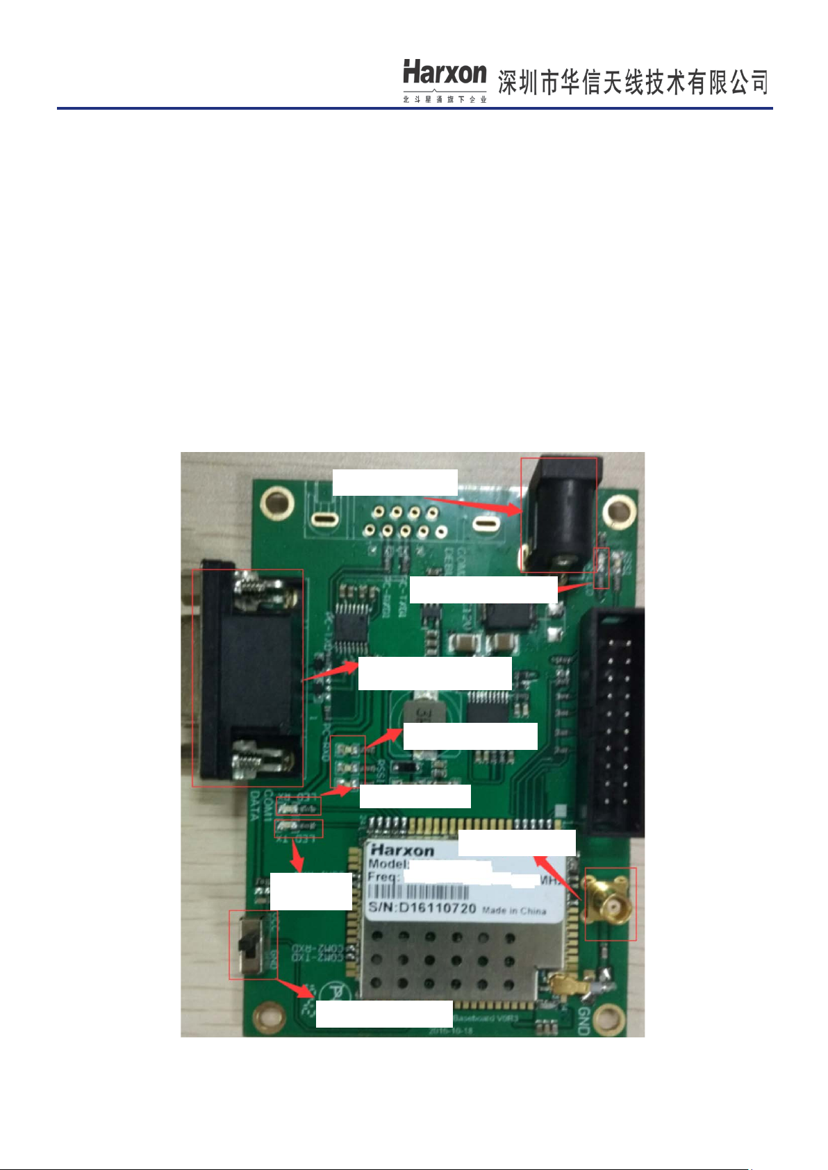
DC power supply
Power indicator light
RS232 (Data port)
RSSI indicator light
Receiving LED
Antenna interface
Sending
LED
Configuration switch
1 Preparatory Work
DC power supply (two units, with the maximum current of 2A), power line (two pieces), serial port line or
USB-to-serial port line (two pieces), computer (one unit), and serial port debugging assistant (sscom32);
2 Operation Steps
2.1 Environment Setup
First, connect the power line of the baseboard, with supply voltage 8-30 V(the supply voltage is usually chosen to
be 12 V). Then, set the configuration switch to the VCC terminal (left). Next, connect the baseboard to the
computer with RS232 DB9 serial port line or USB-to-serial port line (Special notes: Connect the baseboard to
the computer through RS232 data port; this port has a level of 232 rather than TTL level). Open the serial
port debugging assistant (sscom32), select the serial port number, and configure the baud rate of the serial port to
be 115200, and correctly install the radio module antenna (frequency band: 902.6M-927.8M), as shown in the
figure below:
Page 3 of 16

[HX-DU2017D Operating Instructions]
2.2 Powering Up the Baseboard by Switching on the Power Supply
After the power supply is switched on, the power indicator light is on. In the operating mode of the master
radio, LED TX indicator light flickers once two seconds on a PP (point to point) basis, and constantly flickers on
a PMP (point to multipoint) basis. In the operating mode of the slave radio, RSSI indicator light flickers like a
waterfall light before the synchronization of the master and the slave. Such RSSI indicator light stops flickering
when this synchronization is completed. This synchronization is indispe nsable for transmission o f user data.
As data is sent, TX LED red indicator light illuminates; as data is received, RX LED green indicator light
illuminates (Remarks: The red indicator light replaces the green one temporarily since the latter does not
have enough luminance).
2.3 Modifying Radio Parameters
(1) First, set the configuration switch to the right (close to the silk-screen GND terminal) or send the character
string "+++" (pay attention to the sending method: Within one second before sending "+++", make sure that
no data is available; within one second after sending "+++", make sure that no data is available; no codes of
carriage returns and line feeds follow such character string sent), namely, the radio goes into the parameter
configuration mode (showing "NO CARRIER OK");
(2) Then, input the parameter modification command (see Appendix I "List of AT Commands of the Radio");
(3) After modifying a parameter, input the parameter saving command (AT&W); otherwise, that parameter is
not saved in the case of power failure;
(4) Finally, set the configuration switch to the left (silk-screen VCC terminal) or run the command ATA,
namely, allow the radio to work in a normal mode (other than AT command configuration state);
(5) Restart the radio.
Notes: (1) Any AT commands must be followed by carriage returns and line feeds (In the serial
port assistant tools, choose "Send the New Line". Sending the new line indicates that software
automatically adds two characters of carriage returns and line feeds); (2) if the current
configuration pin is grounded, sending "+++" and running the ATA command are invalid.
Page 4 of 16
[HX-DU2017D Operating Instructions]
3 Appendixes
3.1 List of AT Commands of the Radio
Format of the AT command
Format of the parameter configuration command: ATS + register number = value + carriage return and line
feed; for example, ATS103=7
Format of the parameter query command: ATS + register number?+ carriage return and line feed; for
example, ATS103?
Remarks:
(1) After modifying the parameter by the AT command, surely save this parameter by the AT&W command;
(2) Black bold font indicates the ex-work default value;
(3) AT commands without special instructions apply to both the narrow band mode and the frequency-hopping
mode.
The first category of commands: special AT commands
(1) Parameter saving command
Send the command: AT&W+ carriage return and line feed
Set successful return to "OK".
Notes: If a user modifies the radio parameter, and desires to save it upon power failure, he must send the
parameter saving command AT&W upon modification. Otherwise, such parameter will become missing
upon power failure.
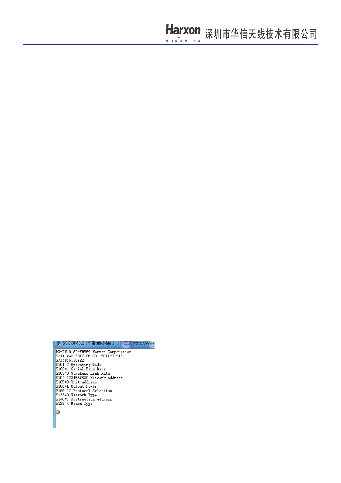
(2) Display of the current working parameters of the radio
Send the command: AT&V+ carriage return and line feed
Set successful return to "OK".
After this command is executed, most parameters of the radio appear; for example:
Page 5 of 16
 Loading...