

Page 1
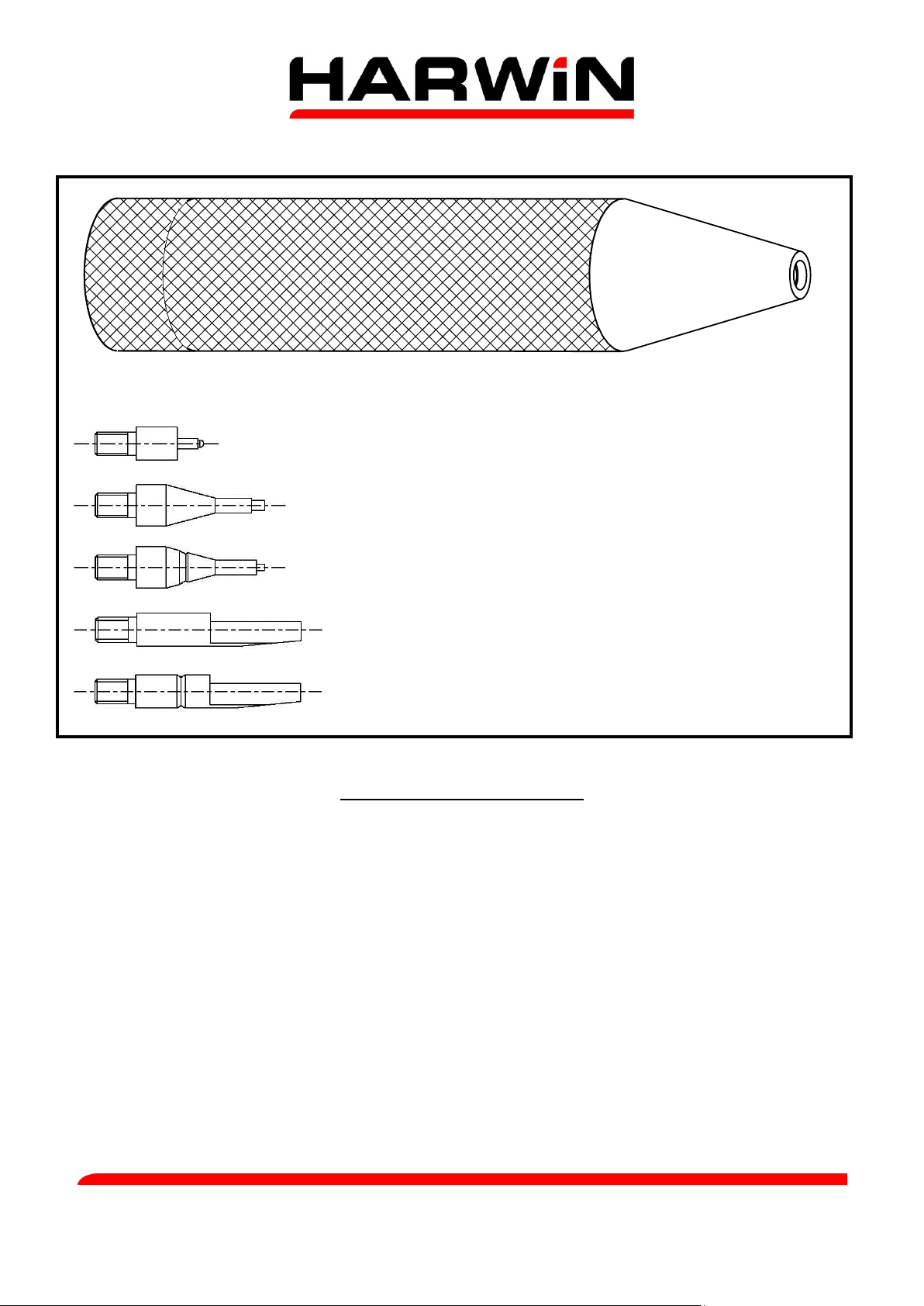
Insertion/Extraction Tool Holder
DATAMATE ASSEMBLY TOOL Z80-280
Extraction Tool (Female contacts L-Tek and J-Tek)
Extraction Tool (Male contacts L-Tek only)
Extraction Tool (Male contacts J-Tek only)
Insertion Tool (for insulation up to Ø0.9mm)
Insertion Tool (for insulation from Ø0.9mm to Ø 1.1mm)
INSERTION PROCEDURE
1. Strip the wire and crimp the socket onto the wire, ensuring that the correct part is used (see
Instruction Sheet IS-01, Hand Crimp Tool M22520/01).
2. Ensure all parts (moulding and crimp sockets) are clean and ready for final assembly.
3. Select the appropriate insertion tool for the wire size in use and attach to the handle. The
different tools can be found by unscrewing the cap at the end of the handle (see above for
tool identification).
4. Place the crimped contact partially into the moulding. The correct position is reached when
approximately 1.5-2mm of socket protrudes (see Figures 2 and 3).
5. Place the insertion tool over the wire, with the wire sitting in the groove and the tool
resting on the back of the crimped socket (see Figure 1).
6. To complete the assembly, push firmly on the rear of the contact while ensuring the tool
remains perpendicular to the mould face. There will be an audible click when the socket is
correctly seated within the moulding.
Harwin North America Harwin Europe Harwin Asia
T: +1 603 893 5376 F: +1 603 893 5396 T: +44 (0) 23 9231 4545 F: +44 (0) 23 9231 4590 T: +65 6 779 4909 F: +65 6 779 3868
E: misboston@harwin.com W: www.harwin.com E: mis@harwin.co.uk W: www.harwin.com E: mis@harwinasia.com W: www.harwinasia.com
IS-25 Issue: 4 Date: 19.06.12 C/Note: 11759 Page 1 of 3
Page 2
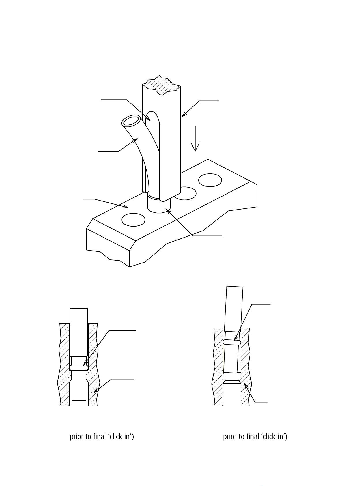
Insertion Tool
Partially
Inserted
Moulding
(back face)
Cable
Groove
Cable
Contact
Moulding
Contact
Moulding
7. Repeat steps 4 to 6 until the moulding is populated as required. Care should be taken not to
damage any contacts. It is recommended that the moulding be supported by a small fixture
or a hard flat surface. Do not support the mould on any latches fitted, or pressure exerted on
inserting the contacts will bend the latches.
Figure 1
Figure 2 Figure 3
(Correct contact position (Incorrect contact position
- -
IS-25 Issue: 4 Date: 19.06.12 C/Note: 11759 Page 2 of 3
Note: Female contact shown
Page 3

Extraction Tool
Moulding
Contact
EXTRACTION PROCEDURE
To remove a contact from the moulding, select the appropriate Extraction Tool from the handle
and attach as before. Place this tool over the mating end of the contact and push firmly. Care
should be taken to keep the tool perpendicular to the mould face, or mould damage may occur.
Figure 4
Note: Male contact shown
IS-25 Issue: 4 Date: 19.06.12 C/Note: 11759 Page 3 of 3
 Loading...