

Page 1
HAND CRIMP TOOL Z80-255
This Hand Crimp Tool has been designed for use with the following Datamate Trio-Tek Signal
Crimp Contacts:
M80-28300XX .............. Female crimp contact for 22-24 AWG wire, supplied loose
M80-28400XX .............. Female crimp contact for 26-28 AWG wire, supplied loose
M80-25300XX .............. Female crimp contact for 22-24 AWG wire, supplied reeled
M80-25400XX .............. Female crimp contact for 26-28 AWG wire, supplied reeled
Harwin recommend the use of BS 3G 210 Type A PTFE Equipment Wire or near equivalent.
Wire
Contact
Gauge
(AWG)
M80-25300XX
22 19/0.15 0.3358 1.10
or
M80-28300XX
M80-25400XX
24 7/0.20 0.2199 0.95 29N
26 7/0.15 0.1237 0.80
or
M80-28400XX
28 7/0.12 0.0792 0.71 9.8N
Harwin North America Harwin Europe Harwin Germany Harwin Asia
T: +1 603 893 5376 T: +44 (0) 23 9231 4545 T: +49 (0) 89 3791 9400 T: +65 6 779 4909
E: misboston@harwin.com E: mis@harwin.co.uk E: wpohl@harwin.com E: mis@harwin.com.sg
Typical Stranding
(no of strands/Ø
mm)
Conductor
cross-sectional
area (mm²)
Max Insulation
diameter (mm)
Crimp
height
(mm)
0.76 –
0.82mm
0.50 –
0.56mm
Minimum
pull-off
force
45N
18N
IS-27 Issue: 6 Date: 14.11.11 C/Note: 11542 Page 1 of 9
Page 2

general information
The Hand crimp tool Z80-255 consists of a Rigidus Hand Crimp Tool with a die-set (Z80-244) designed for Trio-Tek
crimp contacts. The tool is supplied with a locator (Z80-259), fitted to the rear of the tool, to ensure correct and
consistent location of the crimp contacts within the tool.
The Rigidus Hand Crimp Tool includes the following features:
Parallel action stroke for accurate and consistent crimp performance
Unique locator design for full visibility of contact and wire insertion
Symmetric crimp dies and locator allow assembly to suit right or left hand users
Lightweight and compact design for easy access
Ergonomic handles shaped for low effort crimping
Ratchet control to ensure completion of crimp cycles
Die closure adjustment function for tool calibration
Lifetime tests exceeding 50,000 cycles
The contact is correctly crimped when the tool is free to open at the fully closed
position, i.e., when the ratchet releases. The tool cannot be opened without completing
the cycle – if the handles have not opened, squeeze the handles together to complete
the cycle.
TOOL PREPARATION – CHANGING FROM RIGHT TO LEFT HAND OPERATION
If the locator is fitted, please see section “Troubleshooting – Replacing the Dies” on page 6 for instructions on
removing the locator.
Ensure that the crimp
tool is at the fully open
position.
Remove the TX-10 TORX head screws
holding the die sets in place.
Reverse the die sets, ensuring that
the small locating marks line up and
are on the outside of the tool.
TOOL PREPARATION – ASSEMBLING THE LOCATOR
Ensure that the crimp
tool is at the fully open
position.
Push down the centre insert of the
locator, as far as it will go.
Insert the top hooks of the
locator into top slots of the tool
frame.
IS-27 Issue: 6 Date: 14.11.11 C/Note: 11542 Page 2 of 9
Page 3
Rotate the locator down, snapping the lower tabs on the locator
Correct position for the
locator.
into the bottom slots on the tool.
WIRE PREPARATION
1. Ensure that the wire to be crimped is within the specified range of sizes for the contact and
the crimp tool. Failure to use the specified wire size will result in poor quality crimps and
possible tool damage.
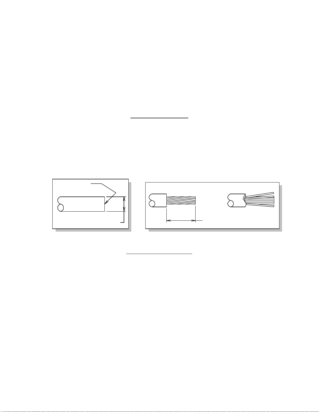
2. Cut the end of the cable to be terminated so that there is a clean cut end (Figure A). Strip
the cable to the correct length (Figure B) using a PTFE Wire stripper, preferably with
adjustable rotating cutter. This should result in all the strands laying together neatly. If the
lay of the strands is disturbed, it may be re-imposed with a slight twist.
Clean cut
Ø1.10mm max
RIGHT WRONG
2.70 – 3.00mm
Figure A Figure B
CRIMPING PROCEDURE
1. Ensure that the crimp
tool is at the fully
open position.
Push the button on the back of the locator, which will
2.
move the locator forward between the crimp dies.
3. Whilst holding the locator in the forward
position, insert the crimp contact into the correct
locator nest. The wire size is marked on the
crimp die, above each location.
IS-27 Issue: 6 Date: 14.11.11 C/Note: 11542 Page 3 of 9
Page 4

Release the locator button, allowing
4.
the crimp contact to move back
between the crimping jaws.
6.
Load the stripped wire
through the terminal, and
against the wire stop inside
the tool.
Close the handle, until the second
5.
ratchet position engages.
Whilst holding the wire against the wire stop,
7.
complete the crimp by squeezing the tool handles
together through the rest of the ratchet clicks –
another 3, to make 5 in total. The handles should
then be free to open. Remove the crimped wire.
CRIMP INSPECTION
Crimp joints should be checked for:
Correctness of form and location of crimp.
Freedom of fracture and rough edges.
Adequate insertion of all conductor strands in the crimp barrel.
Absence of damage to the conductor or the insulation.
Correct crimp height, as per crimp height values given on front page.
A destructive pull-off force test should also be performed occasionally, to confirm the hand crimp
tool is still operating correctly. The correct values for this test are given on the front page of this
instruction sheet. Insulation should be stripped back beyond insulation crimp area before
preparing samples for pull-off force test.
IS-27 Issue: 6 Date: 14.11.11 C/Note: 11542 Page 4 of 9
Page 5

Crimp Inspection Areas
CRIMP INSPECTION (CONT.)
Target
2
1
4 5
3
6
1. Insulation Inspection window
2.
Bellmouth
3.
Conductor Inspection window
4.
Insulation crimp area
5.
Conductor crimp area
6.
Contact stop ear
Insulation extends past Insulation
crimp area, but does not enter
Bellmouth.
Insulation crimp does not cut or
break Insulation.
Insulation crimp is fully wrapped
around and supporting insulation.
Conductors extend past conductor
crimp area, but not past contact
stop ear.
Acceptable
Insulation in-line with end of crimp
area.
Conductor in-line with end of crimp
area.
Insulation butted up to but not
entering bellmouth.
Conductor in-line with contact stop
ear, but not past.
IS-27 Issue: 6 Date: 14.11.11 C/Note: 11542 Page 5 of 9
Page 6

Deffects
Insulation crimp incorrectly formed.
Conductor trapped in Insulation crimp.
Conductor outside of crimp area.
Insulation not visible in Inspection
window.
Conductor not visible in Inspection
window.
Insulation enters bellmouth
Conductor extends past stop ear
IS-27 Issue: 6 Date: 14.11.11 C/Note: 11542 Page 6 of 9
Page 7

ASSEMBLY – CRIMP INTO HOUSING
The completed crimp can now be inserted into the appropriate Trio-Tek crimp housing. For larger
wire sizes, no other tooling should be required for this operation; the crimps can be pushed in by
hand. Crimps are assembled into the mould with the retaining tang towards the outer edge of
the housing. With thinner wires, it may be helpful to push onto the back of the crimp with the
Extraction Tool Z80-258.
If it is necessary to remove a crimp once assembled, please see Instruction Sheet IS-28 for details
on the Extraction Tool Z80-258.
TROUBLESHOOTING – MISCRIMPS OR JAMS
Should the tool become
stuck or jammed in a
partially closed position,
Do Not force the handles
open or closed. There is
a ratchet release lever
located inside the
movable handle.
Pressing up on this lever
will release the ratchet,
and the handles should
then easily open. The
jam or miscrimp can then
be removed.
TROUBLESHOOTING – LOW PULL-OFF FORCE
This tool is supplied as new, set to the right preload force necessary to crimp the Trio-Tek
contacts. However, over time, this force may fall off slightly. The tool can be adjusted to cater
for this wear, and raise the preload force to give correct crimps.
If you need to carry out this procedure, Harwin recommend that you crimp a number of samples
before and during adjustment, until the pull-off force achieved exceeds the minimum values
shown on the first page of this instruction sheet.
.
Ensure that the crimp tool
is at the fully open
position
IS-27 Issue: 6 Date: 14.11.11 C/Note: 11542 Page 7 of 9
Hold the hand tool as shown in the above figure, and
squeeze the link bar in towards the top of the tool. This
releases the preload adjustment wheel.
Page 8

Rotate the setting wheel to a different setting – the higher the number displayed, the higher the
preload force.
Release the link to lock the wheel in place.
If the wheel has been set to the maximum setting possible, then the tool is no longer capable of
achieving the minimum pull-off force and should be replaced.
TROUBLESHOOTING – REPLACING THE DIES
If you need to remove the dies to clean the tool, or replace the dies due to damage, then this
section will tell you how to remove the locator and the dies.
If you need to replace the die-set, spare die-sets are available from Harwin. Please request Part
Number Z80-244.
Removing the Locator:
Squeeze gently on the lower area of
2.
1. Ensure that the crimp tool is at the
fully open position.
the locator shown in the above
picture, with your thumb and index
finger.
3.
Lift the bottom of the locator and
swing it away from the tool.
The upper hooks should slip out of
4.
the top slots easily.
Removing and Replacing the Die Set:
Please see the instructions detailed within the section “Tool Preparation – Changing from Right to
Left Hand Operation”, on page 2.
Replacing the Locator:
Please see the instructions detailed within the section “Tool Preparation – Assembling the
Locator”, on page 2.
IS-27 Issue: 6 Date: 14.11.11 C/Note: 11542 Page 8 of 9
Page 9

CARE OF TOOL
Although the Rigidus tool is engineered for durability, it is recommended that the following
maintenance points are observed, to maximise the life of the tool.
1.
Remove dust, moisture, and other
contaminants with a clean brush, or
soft, lint-free cloth.
2.
Do not use any abrasive materials
that could damage the tool.
3.
All pins, pivot points and bearing
surfaces should be covered with a
thin coat of high quality machine oil
– do not oil excessively. Light oil
(such as 30 weight automotive oil)
used at the oil points shown in the
diagram, is recommended.
Wipe excess oil from hand tool, particularly from the crimping area. Oil transferred onto
4.
crimp contacts may affect the electrical characteristics of the connector.
5.
When tool is not in use, keep the handles closed to prevent objects from becoming lodged
in the crimping dies, and store the tool in a clean, dry area.
ADVICE ON USE
Wear eye protection at all times.
Manual tools such as this Rigidus tools are intended for low volume use. Repetitive,
high-volume use is not recommended.
The insulated rubber handles are not designed or certified for protection against
electrical shock.
Use with the Trio-Tek crimp contacts listed on the first page of this instruction sheet.
This tool is designed for hand use only, and must not be used with clamping, fixturing or use of
handle extensions.
If you have any questions about this instruction sheet, or the Trio-Tek range of Datamate
connectors, please contact datamate@harwin.com
.
IS-27 Issue: 6 Date: 14.11.11 C/Note: 11542 Page 9 of 9
 Loading...