

Page 1
HAND CRIMP TOOL Z30-020
This Hand Crimp Tool has been designed for use with the following crimp contacts:
M30-1000046................................ 1.25mm Pitch Crimp Contacts, Reeled, Tin
M30-1010046................................ 1.25mm Pitch Crimp Contacts, Strip of 10, Tin
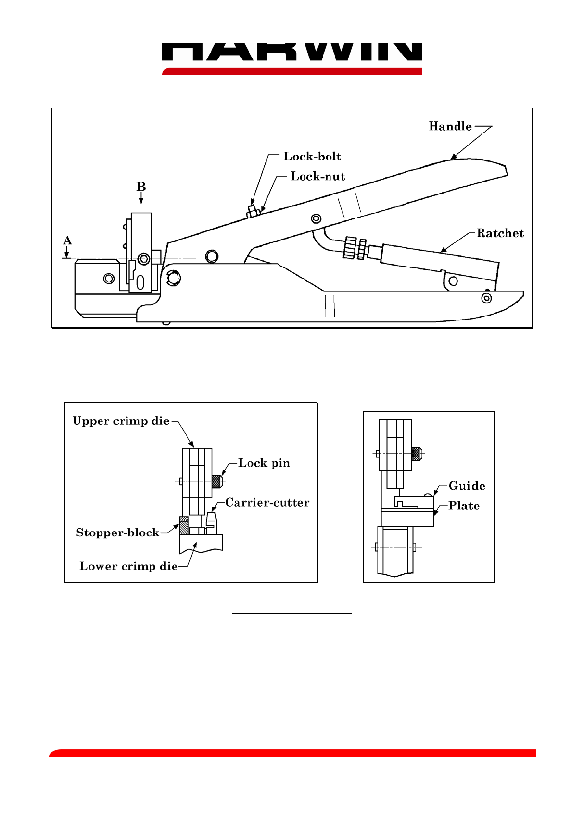
TOOL DESCRIPTION
The Z30-020 Hand Crimp Tool consists of a ratchet mechanism hand tool and a set of jaws. The
jaws comprise of upper and lower crimp dies.
The contact is correctly crimped when the tool is free to open at the fully closed position, i.e.
when the ratchet releases.
Harwin North America Harwin Europe Harwin Asia
T: +1 603 893 5376 F: +1 603 893 5396 T: +44 (0) 23 9231 4545 F: +44 (0) 23 9231 4590 T: +65 6 779 4909 F: +65 6 779 3868
E: misboston@harwin.com W: www.harwin.com E: mis@harwin.co.uk W: www.harwin.com E: mis@harwin.com.sg W: www.harwin.com.sg
IS-13 Issue: 3 Date: 03.10.07 C/Note: 9874 Page 1 of 4
Page 2
CRIMPING PROCEDURE
1. Ensure that the wire to be crimped is within the specified range of sizes for the contact and
the crimp tool. Failure to use the specified wire size will result in poor quality crimps and
possible tool damage.
Wire Gauge Minimum pull-off force (Newtons)
30 AWG 5N
28 AWG 10N
26 AWG 20N
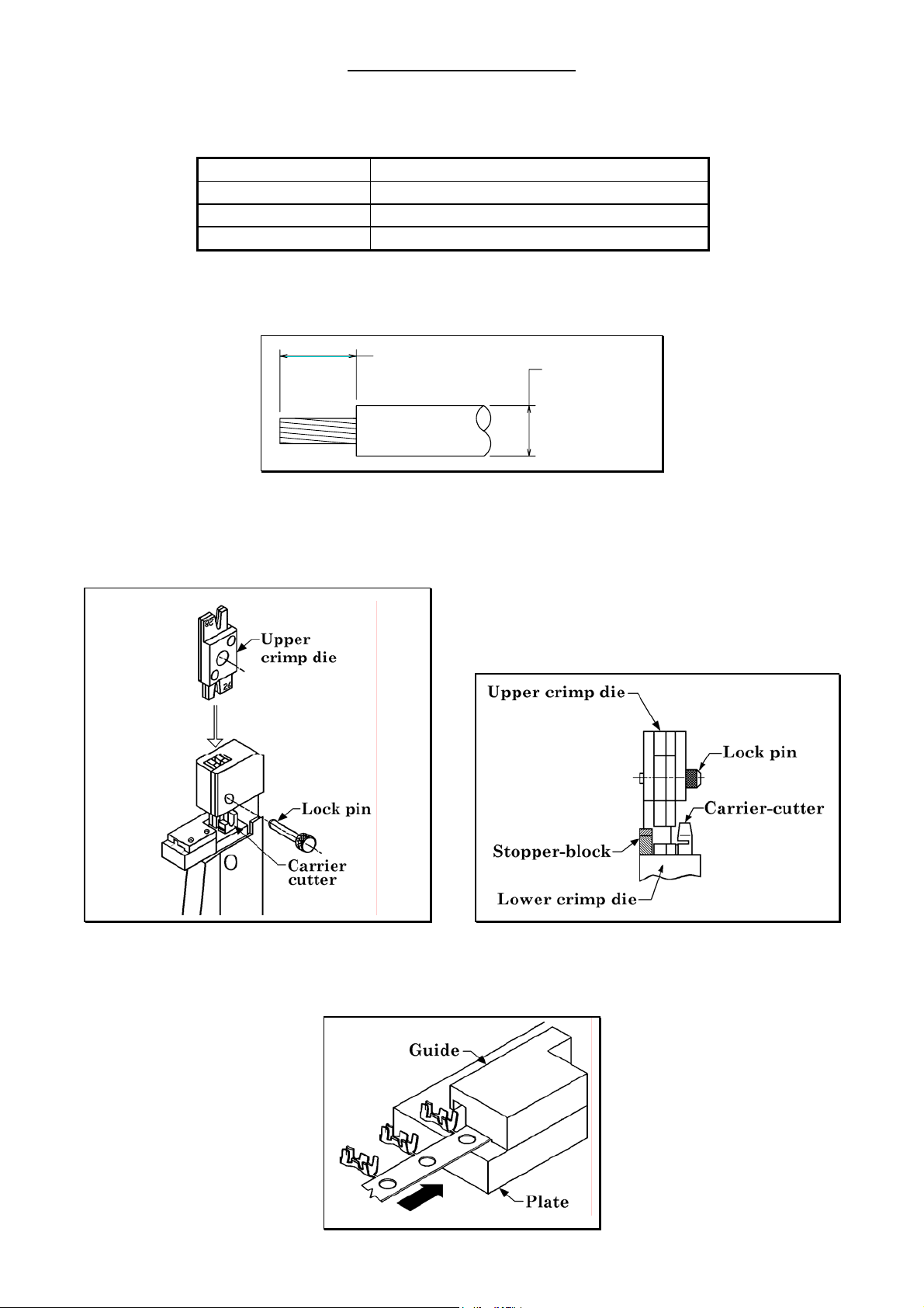
2. The wire insulation covering should be stripped back to 1.5mm. Care should be taken to
avoid cutting or displacing the conductors. If the conductors are displaced, they may be realigned with a gentle twist.
1.5mm
Ø0.8 mm max
3. Make certain that the hand crimp tool is in the fully open position, and that the jaws are free
from dirt and debris.
4. The upper crimp die must be changed so that the correct die set is in place for the correct
wire size. Pull out the lock-pin, and remove the upper crimp die.
5. Exchange or turn the upper crimp die so that the correct jaws will be used for the wire size
required. Replace the upper crimp die and lock-pin.
6. Insert the end of the strip of contacts between the guide and the plate (as shown below).
IS-13 Issue: 3 Date: 03.10.07 C/Note: 9874 Page 2 of 4
Page 3

7. Push the contact until the contact touches the stopper-block. Check that the carrier of the
contact goes into the groove of the carrier-cutter.
Do not push on the contact when the contact touches the stopper-block,
because the contact will become distorted.
8. Compress the hand tool by one notch, then position the cable within the tool as shown
below.
9. Hold the cable steady and fully compress the handle, to complete the crimping operation.
Do not attempt to open the tool before fully compressing it, as this may damage both tool
and crimp.
10. Release the tool, and the handle will open automatically. Remove the cable and the contact
from the crimp tool. Also remove the piece of cut carrier from the tool, as this will jam the
tool if left in position.
11. If the crimped contact cannot be easily removed, a further operation of the tool will loosen
the contact.
IS-13 Issue: 3 Date: 03.10.07 C/Note: 9874 Page 3 of 4
Page 4

INSPECTION
The contact’s mating dimensions can be checked after crimping by gauge plates.
0.1mm thickness gauge should go through mating area.
0.2mm thickness gauge should not go through mating area.
TOOL CARE
We strongly recommend that you:
1. DO NOT open the handle when the handle is tightened halfway.
2. DO NOT crimp any contact and cable other than those recommended.
3. DO NOT drop the crimp tool or damage it in any way.
4. DO NOT use any other power for crimping except the hand.
5. DO NOT take the crimp tool apart.
TOOL MAINTENANCE
1. Keep the tool clean and free from dirt and foreign matter. Use a small brush to clean the
crimped jaws before and after use.
2. At regular intervals, check the crimp tool jaws for wear or damage, and inspect sample
crimps for form and function
3. Spray lubricating oil on moving areas if the crimp tool movement feels unnatural.
4. Store the crimp tool in a closed position, covered and in a dry location.
IS-13 Issue: 3 Date: 03.10.07 C/Note: 9874 Page 4 of 4
 Loading...