

Page 1
HAND CRIMP TOOL Z20-320
26-30
22-24
Z20-320
5
M20-118
This Hand Crimp Tool has been designed for use with the following crimp contacts:
M20-1160042 ................................... 2.54mm Pitch Crimp Contacts, Reeled, Gold
M20-1160046 .................................. 2.54mm Pitch Crimp Contacts, Reeled, Tin
M20-1180042 ................................... 2.54mm Pitch Crimp Contacts, Loose, Gold
M20-1180046 .................................. 2.54mm Pitch Crimp Contacts, Loose, Tin
Harwin North America Harwin Europe Harwin Asia
T: +1 603 893 5376 F: +1 603 893 5396 T: +44 (0) 23 9231 4545 F: +44 (0) 23 9231 4590 T: +65 6 779 4909 F: +65 6 779 3868
E: misboston@harwin.com W: www.harwin.com E: mis@harwin.co.uk W: www.harwin.com E: mis@harwin.com.sg W: www.harwin.com.sg
IS-15 Issue: 5 Date: 05.10.2011 C/Note: 11479 Page 1 of 4
Page 2
GENERAL INFORMATION
The Z20-320 Hand Crimp Tool consists of a ratchet mechanism hand tool and a set of jaws. The
jaws comprise of upper and lower crimp dies.
The contact is correctly crimped when the tool is free to open at the fully closed position, i.e. when
the ratchet releases.
CRIMPING PROCEDURE
1. Ensure that the wire to be crimped is within the specified range of sizes for the contact and
the crimp tool. Failure to use the specified wire size will result in poor quality crimps and
possible tool damage.
Wire Gauge Minimum pull-off force (Newtons)
30 AWG 9N
28 AWG 11N
26 AWG 18N
24 AWG 29N
22 AWG 45N
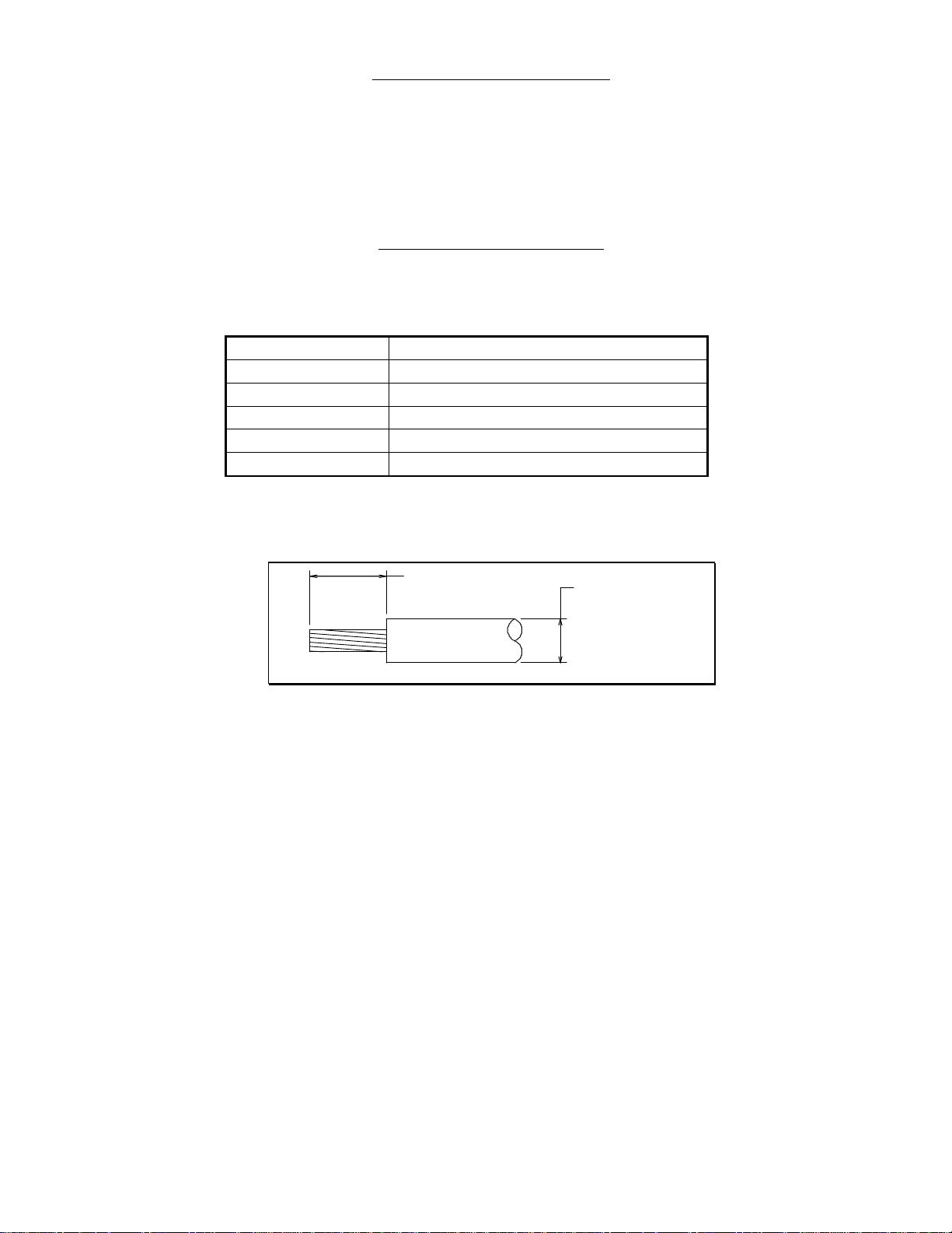
2. Strip the wire insulation to the dimensions shown below. Care should be taken to avoid
cutting or displacing the conductors. If the conductors are displaced, they may be re-aligned
with a gentle twist.
4.0mm max
Ø1.7mm max
3. Make certain that the hand crimp tool is in the fully open position, and that the jaws are free
from dirt and debris.
4. If the socket is on a reel, break or cut off a contact from the strip of bandolier.
5. Place the contact into the correct crimp cavity in the fixed jaw. The markings on the jaw
indicate the correct crimp cavity according to the wire size being used. The orientation of the
contact is with the crimp end uppermost, with the open side of the crimp facing towards the
moving jaw.
6. Partially close the crimp tool until the wire stop comes across the face of the fixed jaw.
7. Take the pre-stripped wire and insert it into the contact so the conductors and insulation are
positioned in the crimp. The conductors should be touching the wire stop.
IS-15 Issue: 5 Date: 05.10.2011 C/Note: 11479 Page 2 of 4
Page 3

8. Keeping the cable steady in the crimp, fully close the hand crimp tool until the ratchet
releases. Let the crimp tool open.
9. After crimping remove the assembly. The process is then repeated for each crimp required.
TOOL MAINTENANCE
1. Keep the tool clean and free from dirt and foreign matter. Ensure that all retaining pins and
clips are in place before use, and that signs of wear are not visible. If the pivots are worn,
the tool must be replaced, or crimp integrity will be compromised.
2. Oil at all pivots and bearings using a light cycle oil.
3. At regular intervals, check the crimp tool jaws for wear or damage, and inspect sample crimps
for form and function. Minimum pull-off forces (as shown in the previous table) should be
achieved when sample is tested. If forces are not achieved, calibrate the tool.
TOOL CALIBRATION
The operating force at the point shown should be 150N (15kg, 33lbs) min.
40mm
If adjustment of the tool becomes necessary due to pull-off forces not being maintained, the
following instructions should be followed.
1. Remove Hex socket grub screw using a 2mm A/F Hex key.
2. Using a screwdriver, turn the numbered wheel via the wheel adjustment screw. To increase
the pre-load (and therefore the crimp pull-off force), turn the screw until the next number is
shown. Even numbers are found by turning the screw clockwise, odd numbers are anticlockwise. Turn the screw until the required number is level with the Hex socket grub screw
hole.
IS-15 Issue: 5 Date: 05.10.2011 C/Note: 11479 Page 3 of 4
Page 4

Hex socket grub screw
320
0-118
5
Wheel adjustment screw
3. Re-fit the Hex socket grub screw and tighten.
4. Check the operating force as shown at the top of the page. Repeat the procedure if the force
is incorrect.
If the adjuster is set to maximum, and operating force is still not achieved, the
tool has finished its working life (50,000 crimps minimum), and will need
replacing.
IS-15 Issue: 5 Date: 05.10.2011 C/Note: 11479 Page 4 of 4
 Loading...