

Page 1
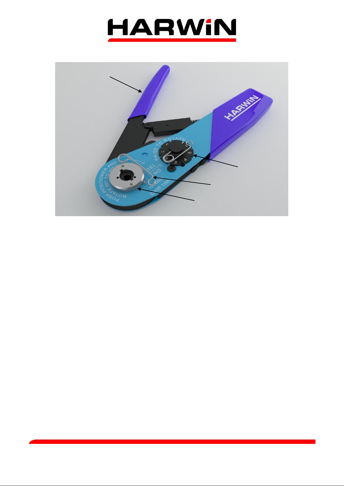
Tool in open
position
Selector knob
Safety clip
Positioner
guide
HAND CRIMP TOOL M22520/2-01
This Hand Crimp Tool has been designed for use with the following Datamate Signal Crimp Sockets (when
used with Positioner T5747):
The following Datamate Signal Crimp Sockets can also be crimped (when used with Positioner Z80-193):
The following Datamate Power Crimp Sockets can also be crimped (when used with Positioner Z80-058):
The following Power Crimp Sockets can also be crimped (when used with Positioner ZK3609-00):
Harwin North America Harwin Europe Harwin Asia
T: +1 603 893 5376 F: +1 603 893 5396 T: +44 (0) 23 9231 4545 F: +44 (0) 23 9231 4590 T: +65 6 779 4909 F: +65 6 779 3868
E: misboston@harwin.com W: www.harwin.com E: mis@harwin.co.uk W: www.harwin.com E: mis@harwinasia.com W: www.harwinasia.com
IS-01 Issue: 5 Date: 19.07.12 C/Note: 11782 Page 1 of 3
M80-01100XX .................. Large bore Female crimp contact for 22 AWG wire
(used in all L-Tek, J-Tek and Mix-Tek female crimp connectors).
M80-01300XX .................. Small bore Female crimp contact for 24-28 AWG wire
(used in all L-Tek, J-Tek and Mix-Tek female crimp connectors).
M80-01900XX .................. Extra small bore female crimp for 28-32 AWG wire
(used in all L-Tek, J-Tek and Mix-Tek female crimp connectors).
M80-04000XX ................. Large bore Male crimp contact for 22 AWG wire
(used in L-Tek male crimp connectors).
M80-04100XX .................. Small bore Male crimp contact for 24-28 AWG wire
(used in L-Tek male crimp connectors).
M80-19400XX .................. Large bore Male crimp contact for 22 AWG wire
(used in J-Tek and Mix-Tek male crimp connectors).
M80-19500XX .................. Small bore Male crimp contact for 24-28 AWG wire
(used in J-Tek and Mix-Tek male crimp connectors).
M80-05500XX .................. Power Female crimp contact for 18-20 AWG
(used in M80-716 and M80-719 series).
K3606-46 ......................... Power Male crimp contact for 18 AWG.
K3607-46 ......................... Power Female crimp contact for 18 AWG.
Page 2
Contact
Crimp Type
Wire Gauge
(AWG)
Stranding
(mm)
Crimp Tool
Setting
Minimum
pull-off force
M80-01100XX
M80-04000XX
M80-19400XX
Large Bore
22
19/0.15
6
50N
M80-01300XX
M80-04100XX
M80-19500XX
Small Bore
24
7/0.2
6
44N
26
7/0.15
6
25N
28
7/0.12
6
12.5N
M80-01900XX
Extra small
bore
28
7/0.12
5
12.5N
30
1/0.25
4
7N
32
7/0.08
4
4N
M80-05500XX
Power Crimp
20
19/0.2
8
85N
18
19/0.26
8
140N
K36XX-46
Power Crimp
18
Variable
8
142N
GENERAL INFORMATION
The Hand crimp tool M22520/2-01 consists of a basic hand tool, which should be used with a
positioner.
The contact is correctly crimped when the tool is free to open at the fully closed position, i.e.,
when the ratchet releases. The tool cannot be opened without completing the cycle.
TOOL PREPARATION
1. Check that the tool is in the open position. Remove the safety clip from the positioner
guide (do not discard).
2. Insert the Positioner into the positioner guide and turn it 90° in the direction shown on the
tool, until the bayonet pins lock.
3. Install the safety clip back into the positioner guide (optional).
4. Check Table 1 for the correct crimp tool setting of the wire size you wish to crimp.
5. Remove the safety clip from the selector knob (do not discard).
6.
7. Install the safety clip back into the selector knob.
CRIMPING PROCEDURE
1. Ensure that the wire to be crimped is within the specified range of sizes for the contact and the
crimp tool. Failure to use the specified wire size will result in poor quality crimps and possible tool
damage.
Table 1
2. Cut the end of the cable to be terminated so that there is a clean cut end (Figure A). Strip the cable
IS-01 Issue: 5 Date: 19.07.12 C/Note: 11782 Page 2 of 3
to the correct length (Figure B) using a PTFE Wire stripper, preferably with adjustable rotating cutter.
This should result in all the strands lying together neatly. If the lay of the strands is disturbed, it
may be re-imposed with a slight twist.
Page 3
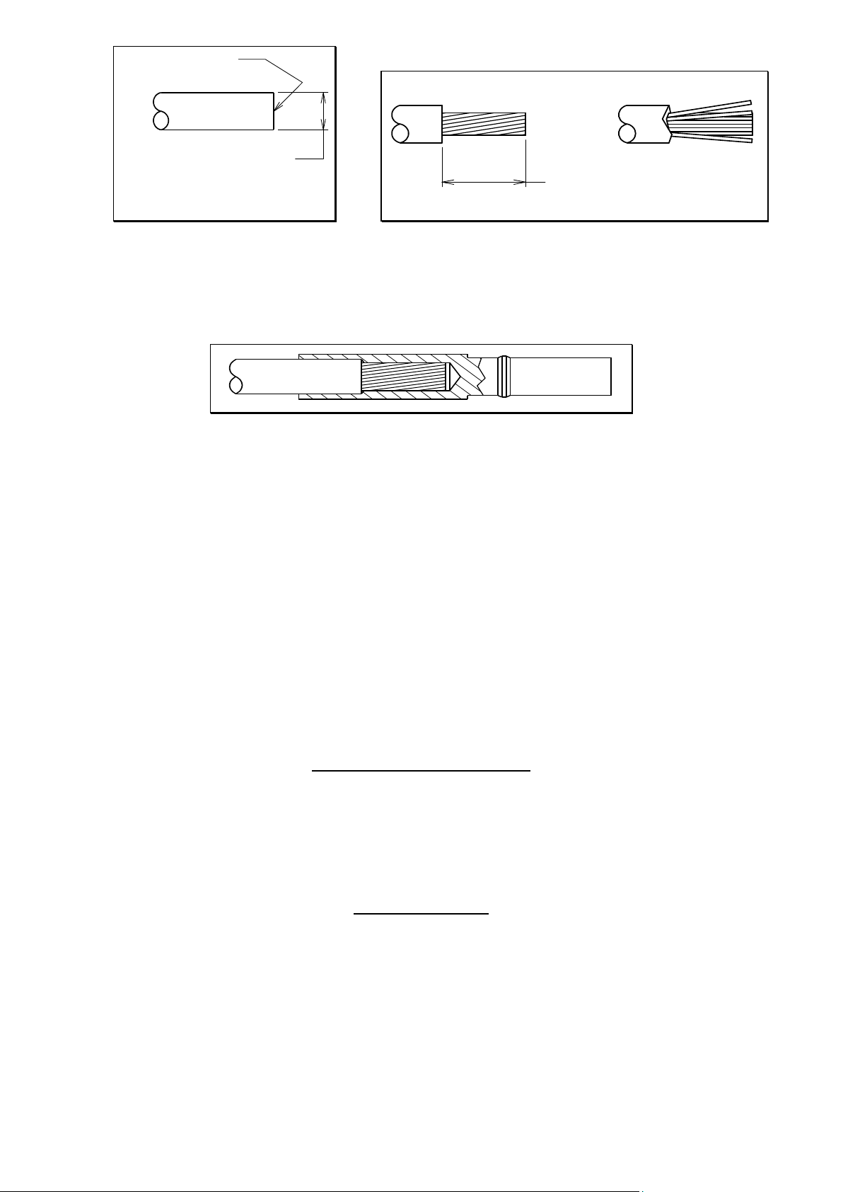
Clean cut
Ø0.75mm max (28-32 AWG
Ø1.10mm max (22-28 AWG)
Ø1.80mm max (18-20 AWG)
RIGHT
WRONG
2.00 ±0.15mm (M80-XXX)
3.75 ±0.25mm (K36XX)
Figure A Figure B
3. Position the crimp socket fully into the positioner, with the crimp barrel uppermost.
4. Load the terminated end of the cable into the crimp barrel of the socket. Ensure the wire is fully
inserted, with all strands in place (see Figure C).
5. Squeeze the handles of the crimp tool fully together, until ratchet releases. The handle will return to
the open position. Remove the crimped socket and wire. Check that there is no exposed or stray
wire, and that the insulation is fully within the end of the crimp socket.
Figure C
Note: The cross hole on the crimp barrel, although not an inspection hole (it is designed to assist
with plating processes) may give approximate guidance to the location of the conductor. After
crimping the contact, the indent may overlap this hole.
6. Crimp joints should be checked for:
a) Correct combination of cable, tool setting and crimp termination.
b) Correctness of form and location of crimp.
c) Freedom of fracture, rough edges and flash.
d) Adequate insertion of all conductor strands in the crimp barrel.
e) Absence of damage to the conductor or the insulation.
M80-XXX piece parts are assembled using the Assembly Tool Z80-280. See Instruction Sheet IS-25 for
details on assembly.
K36XX piece parts are assembled using the Assembly Tool ZK3610-00. See Instruction Sheet IS-22 for
details on assembly.
There is virtually no maintenance required for the M22520/2-01 tool. However, it is good practice to keep
the indenter tips free of residual colour band deposits and other debris. A small wire brush may be used
for this purpose.
We strongly recommend that you:
1. DO NOT immerse tools in any cleaning solution.
2. DO NOT spray oil into tool to lubricate.
3. DO NOT attempt to disassemble tool or make repairs.
This is a precision crimp tool and should be handled as such.
IS-01 Issue: 5 Date: 19.07.12 C/Note: 11782 Page 3 of 3
ASSEMBLY PROCEDURE
CARE OF TOOL
 Loading...