

Page 1
MODEL Q-8DS
INSTALLATION INSTRUCTION SHEET
STRAIN RELIEF NUT
GROMMET ‘A’
GROMMET ‘AA’
GROMMET ‘B’
GROMMET ‘C’
SWITCH COVER
4 RETAINING SCREWS
(NOT SHOWN)
“F” COVER
O-RING
BODY, COMPLETE WITH
FEED THRU SHAFT ASSEMBLY
(SEE PARTS LIST)
HARWIL CORPORATION
541 KINETIC DRIVE, OXNARD, CA 93030
TEL: (805) 988-6800 FAX: (805) 988-6804
EMAIL: [email protected]
“F” COVER TO SUIT CUSTOMER
SUPPLIED FITTING FOR ½”
FLEXIBLE CONDUIT
MICROSWITCH COMPLETE
W/ 2 SLIP-ON TERMINALS
SCREW x ¾” LG
NUT
PLAIN WASHER
SPLIT LOCKWASHER
1” NPT
DO NOT ATTEMPT TO REMOVE
DRAG STRIP WITHOUT FIRST
GRIPPING SEAL SHAFT TO
PREVENT BREAKING OF SEAL
BY UNTHREADING FROM FEED
THRU SHAFT.
FLUID FLOW SWITCH
PARTS LIST
SCREW x 7/8” LG
NUT
PLAIN WASHER
SPLIT LOCKWASHER
DRAG STRIP
CLAMP WASHER
DAMPENER WASHER
SCREW x 3/8” LG
2 PLAIN WASHERS
SPLIT LOCKWASHER
2D
5D
TURBULENT
FLOW REDUCTION
MOUNT IN
THREE POSITIONS
ULTRA RELIABLE SINCE 1956 P. 1
Page 2
HARWIL CORPORATION
541 KINETIC DRIVE, OXNARD, CA 93030
MODEL Q-8DS
TEL: (805) 988-6800 FAX: (805) 988-6804
EMAIL: [email protected]
INSTALLATION INSTRUCTIONS
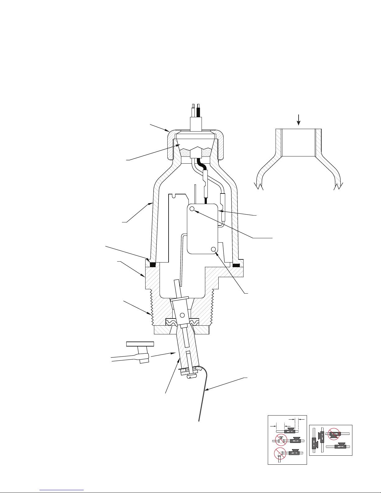
Model Q-8DS is normally mounted in a 1½” x 1½” x 1” or 2” x 1” SST PVC Tee, which may be
plumbed into the system in vertical or horizontal lines, right side up or inverted using normal PVC
pipe cement. Make sure that flow direction arrow on the cover is aligned with the flow in the pipe.
An unmounted Q-8DS should be threaded into the 1” NPT stem of the Tee after checking for uniform
coating of threads with Teflon tape. Tighten sufficiently to produce a leak-tight seal and continue tightening up to one full turn to align flow direction arrow on cover parallel with flow axis of Tee. Check
through open end of Tee that drag strip moves freely and is perpendicular to the flow axis. Install in
pipe with flow direction arrows pointing correctly in flow direction.
ELECTRICAL WIRING
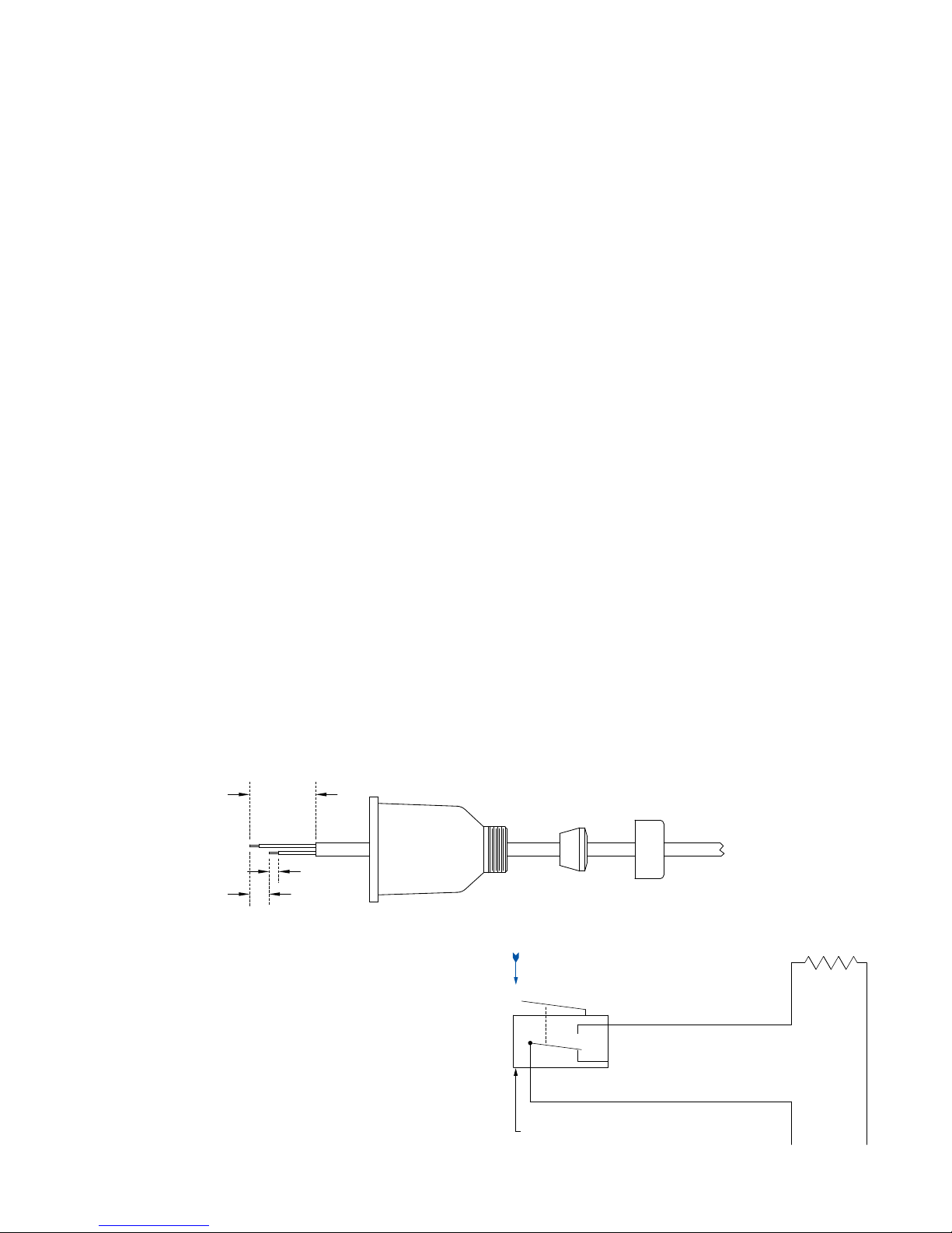
1. Remove strain relief nut, grommet, and switch
cover.
2. Strip outer jacket of electrical cord back approximately 1¼”, stagger ½” and strip leads
¼”.
3. Remove slip-on connectors from microswitch
terminals and crimp or solder to leads.
4. Feed cable through strain relief nut, grommet,
and cover.
5. Apply slip-on connectors to appropriate terminals of microswitch. Slide cover down cable
and fasten to body with 4 screws. Slide grom-
1¼”
¼”
½”
met down cable until small end is level with
outer jacket. Push grommet into tapered hole
of cover, hold cable jacket to prevent rotation
and tighten strain relief firmly.
6. If type “F” cover is supplied, connect desired
conduit fitting to cover. Prepare leads, attach
to slip-on connectors per STEP 2 and apply
to appropriate microswitch terminals. Attach
electrical conduit-to-conduit fitting. Exercise
reasonable care when assembling metal flexible conduit to prevent fracture of plastic cover.
Rigid conduit is not recommended.
WIRING SCHEMATIC
Contacts are closed when flow rate is above
microswitch set point (15-20 GPM). Power to load
interrupted when flow decreases below this point.
INCREASING FLOW MOVES
ACTUATOR IN DIRECTION
SHOWN
NC
NO
HOT
COM
MICROSWITCH
ULTRA RELIABLE SINCE 1956P. 2
LOAD
LINE
Page 3
MODEL Q-8DS
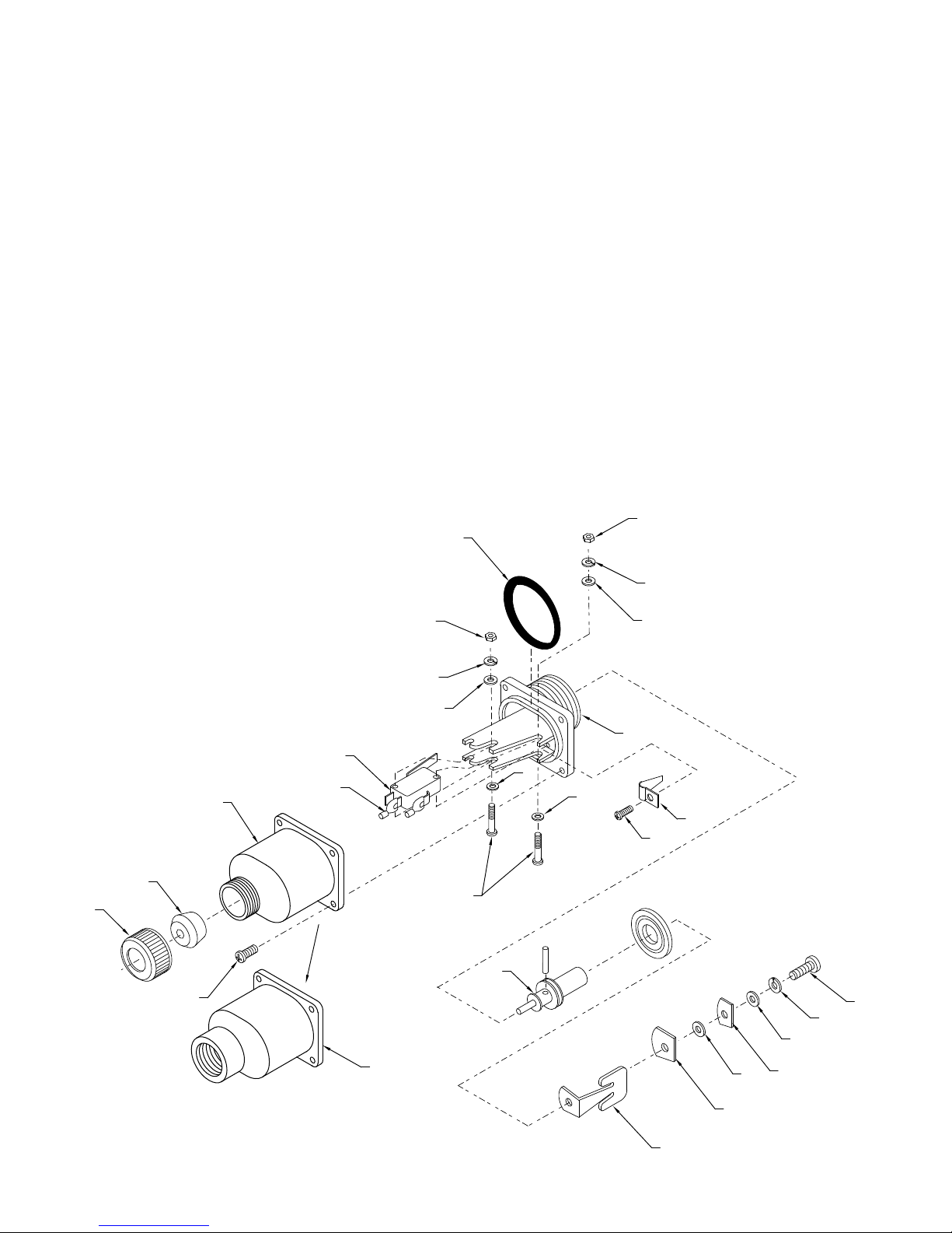
Q-8DS (SERIES 65000)
# PART NAME QTY PART #
1 BODY WITH SWITCH BRACKET (1) 65101
2 FEED THRU SHAFT (ASSEMBLY ONLY) (1) 65103
A) SEAL SHAFT (1) 65104
B) DIAPHRAGM (1) 65105
C) DIAPHRAGM WASHER (1) 65106
D) PIVOT PIN (1) 65107
E) CROSS PIN (1) 65108
3 MICROSWITCH (1) 65109
4 SCREW (2) 119-S
5 WASHER (2) 301-W
6 WASHER (2) 300-W
7 WASHER (3) 311-W
8 NUT (2) 219-N
9 O-RING (1) 65110
10 SPRING (1) 65111
11 SCREW (1) 102-S
12 CLAMP WASHER (1) 65112
13 WASHER (2) 300-W
14 DAMPENER WASHER (1) 65113
15 WASHER (1) 302-W
16 SCREW (1) 120-S
# PART NAME QTY PART #
17 DRAG STRIP (OPTIONAL)
A - DRAWING 10502 (1) 65115
B - DRAWING 10507 (1) 65116
C - DRAWING 10512 (1) 65117
D - DRAWING 10539 (1) 65118
E - DRAWING 10564-A (1) 65119
F - DRAWING 10566 (1) 65120
G - DRAWING 10570-A (1) 65121
H - DRAWING 10593 (1) 65122
I - DRAWING 10596 (1) 65123
J - DRAWING 10600 (1) 65124
18 TERMINALS (3) 706-T
19 COVER (MALE) (OPTIONAL) (1) 60125
20 COVER (FEMALE) (OPTIONAL) (1) 60126
21 SCREW (4) 109-S
22 GROMMET #A (OPTIONAL) (1) 10440
GROMMET #AA (OPTIONAL) (1) 10441
GROMMET #B (OPTIONAL) (1) 10442
GROMMET #C (OPTIONAL) (1) 10443
23 STRAIN RELIEF NUT (1) 60127
9
HARWIL CORPORATION
541 KINETIC DRIVE, OXNARD, CA 93030
TEL: (805) 988-6800 FAX: (805) 988-6804
EMAIL: [email protected]
8
23
22
21
19
18
7
8
7
6
3
6
5
4
2
5
1
10
11
16
7
15
20
12
17
13
14
ULTRA RELIABLE SINCE 1956 P. 3
Page 4

CERTIFICATE OF CONFORMANCE
All Harwil Corporation (“HARWIL”) products are manufactured using new materials and components.
Our products meet the applicable performance and materials specifications indicated in our current
Specifications Sheets and Parts List. HARWIL endeavors to obtain its materials and components from
American Companies.
DOMINANCE OF HARWIL LIMITED EXPRESS WARRANTY
Each user MUST make appropriate analysis and tests to determine the suitability of the HARWIL product
for the intended use prior to purchase.
HARWIL warrants that all HARWIL products will be free from defects in material and workmanship for a
period of one year from the date of original shipment. This Warranty shall be LIMITED to the replacement
and reconditioning of our products and parts. HARWIL reserves the right and sole discretion to modify
or change the composition, design and appearance of its products at anytime.
THIS WARRANTY SHALL BE IN LIEU OF ALL WARRANTIES OF MERCHANTABILITY AND OF ALL WARRANTIES OF FITNESS FOR A PARTICULAR PURPOSE RELATING TO HARWIL PRODUCTS AND PARTS.
BUYER’S SOLE REMEDY SHALL BE REPLACEMENT OR RECONDITIONING AS SET FORTH HEREIN.
HARWIL SHALL INCUR NO OBLIGATIONS HEREUNDER AND NO LIABILITY IN THE EVENT OF (1)
BUYER NOT FULFILLING ITS RESPONSIBILITIES; INCLUDING AS SET FORTH HEREIN; (2) NEGLECT,
ALTERATION OR IMPROPER PRODUCT USE, INCLUDING USE WITH NON-COMPATIBLE DEVICES OR
CHEMICALS; OR (3) REPAIR BY ANOTHER COMPANY OR PERSON THAN HARWIL.
ANY LAWSUIT RELATING TO THIS LIMITED EXPRESS WARRANTY MUST BE COMMENCED WITHIN
ONE YEAR OF THE DATE THE LAWSUIT ACCRUES.
HARWIL provides NO WARRANTY and ASSUMES NO RESPONSIBILITY for corrosive attack on
any material, component or design features associated with any of its products.
Corrosion resistance information listed in HARWIL specification sheets, information sheets and product
brochures is solely for general background information. This information table has been compiled from
literature published by various material suppliers and by equipment manufacturers who use these materials in their products. Inasmuch as these data are based on tests by entities over which HARWIL has no
control, HARWIL DOES NOT GUARANTEE AND DOES NOT ACCEPT ANY RESPONSIBILITY FOR THE
ACCURACY OF SUCH THIRD PARTY TESTING. When using the table, please remember that in any
given case several factors such as concentration, temperature, degrees of agitation and presence of impurities influence the rate of corrosion. The information table is intended, in a general way, to rate materials
for resistance to chemicals which contain their usual impurities and for types of equipment in common
use. Ratings should be used only as a general tool to first approximation of your material requirements
rather than as the final answer.
WHEN IN DOUBT, TEST MATERIALS BEFORE INSTALLATION.
AFTER INSTALLATION, FOLLOW UP WITH SCHEDULED PREVENTATIVE MAINTENANCE AND
PERIODIC INSPECTION.
ULTRA RELIABLE SINCE 1956P. 4 ULTRA RELIABLE SINCE 1956
163 06
 Loading...