

MODEL Q-12
REED SWITCH
Q-12N, Q-12CR, Q-12 DS (TEMPERATURE: QT-12)
INSTALLATION INSTRUCTION SHEET
HARWIL CORPORATION
541 KINETIC DRIVE, OXNARD, CA 93030
TEL: (805) 988-6800 FAX: (805) 988-6804
EMAIL: HARWIL@HARWIL.COM
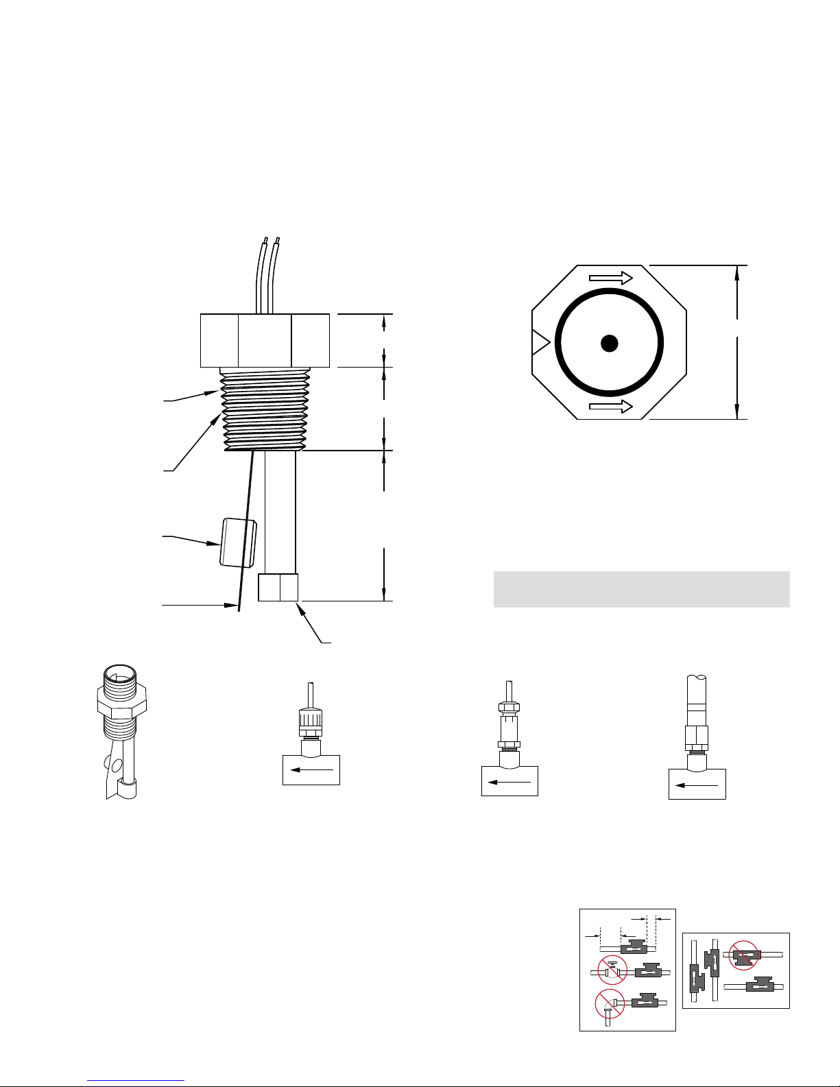
½” OR ¾” NPT
APPLY TEFLON
SEALING TAPE
AS REQUIRED
(2-3 LAYERS)
ENCAPSULATED
MAGNET
ONE PIECE
BENDING BEAM
TARGET AND
MAGNET
SIDE VIEW
0.5”
0.65”
1.1” SMALL BODY
1.4” MEDIUM BODY
1.8” LARGE BODY
ENCAPSULATED
TOP VIEW
1.2”
• Pressure drop typically less than 1.0 psi
at rated flow.
• Mount in any position.
OPTION 3 GROMMET SELECTION CHART
Grommet
Size
A 0.25” B 0.375”
AA 0.33” C 0.50”
Cable OD Grommet
Size
Cable OD
OPTION 1
BASIC UNIT SUPPLIED WITH
TWO 0.187 x 0.020 MALE
SPADE TERMINALS RECESSED
IN ½” NPT NIPPLE SECTION.
OPTION 2
BASIC UNIT WITH TWOCONDUCTOR INSTRUMENT
CABLE POTTED IN PLACE.
PVC TEE OPTIONAL.
FLUID FLOW SWITCH
ULTRA RELIABLE SINCE 1956 P. 1
OPTION 3
BASIC UNIT W/ DMP TAPERED
RUBBER GROMMET ATTACHMENT
FOR WATERTIGHT SEAL & STRAIN
RELIEF. PVC TEE OPTIONAL.
OPTION 4
BASIC UNIT WITH ½” FLEXIBLE
SPIRADUCT PLASTIC CONDUIT &
FITTINGS. ELECTRICAL CABLE NOT
SUPPLIED. PVC TEE OPTIONAL.
2D
5D
TURBULENT
FLOW REDUCTION
MOUNT IN
THREE POSITIONS
MODEL Q-12
Q-12N, Q-12CR, Q-12 DS (TEMPERATURE: QT-12)
INSTALLATION INSTRUCTIONS
HARWIL CORPORATION
541 KINETIC DRIVE, OXNARD, CA 93030
TEL: (805) 988-6800 FAX: (805) 988-6804
EMAIL: HARWIL@HARWIL.COM
Flow switch should be mounted at least 5 pipe diameters
downstream and 2 pipe diameters upstream of any source
of turbulence, such as valves, elbows, reducers, etc.
1. Remove unit from shipping box and inspect it for possible damage (i.e., cracks, damaged threads, deformed
bending beam, etc.)
2. Check model number on label with that shown on
packing list vs. configuration actually received (return to
supplier if discrepancy is found).
3. Place a multimeter or equivalent test meter across the
two wire leads coming from the unit and check for
proper switch operation by gently moving bending
beam and magnetic assembly toward switch support
tube. Switch should activate when separation is in the
range ⁄” to ⁄”.
4. If no discrepancy is found, thread unit into appropriate
tee.
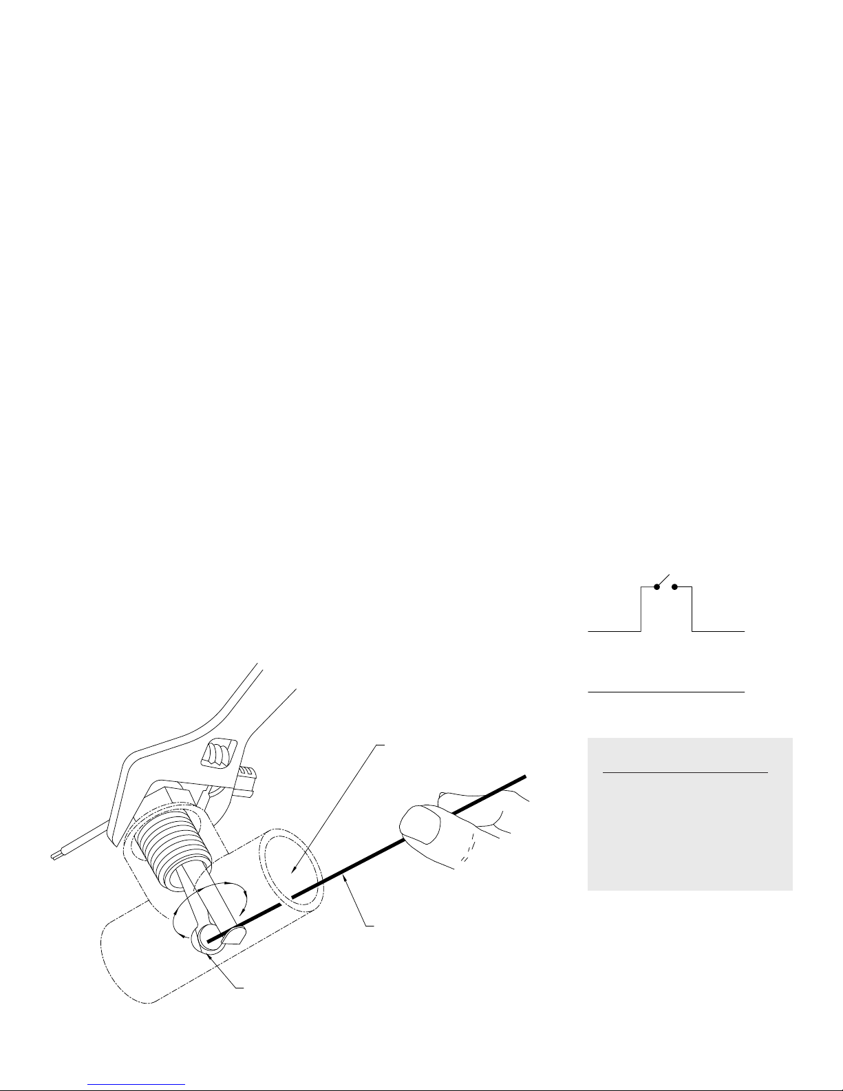
5. Care must be exercised during threading operation to
CAUTION
INSTALLATION
OR REMOVAL
OF FLOW
SWITCH FROM
SMALL TEE
insure threads are not crossed and the bending beam
target assembly does not touch the inside surface of the
tee.
NOTE: It may be necessary to test fit the unit in a tee
identical to the tee mounted in the flow line to ensure
adequate clearance during rotational insertion sequence.
For black iron and galvanized tees, check for possible hang
up of bending beam due to attraction of magnet to interior
metal wall.
6. Tighten unit in tee until fluid leaks are eliminated, flow
target is approximately centered along axis of pipe
and flow direction arrows located on unit are aligned
parallel with flow in pipe. When threading into PVC fittings 2-3 layers of Teflon sealing tape is recommended.
Tighten 2-3 turns beyond finger tight.
7. Complete wiring to signal processor, light, relay, etc.
per local code.
WIRING DIAGRAM
FLOW SWITCH
HOT
FROM POWER
SOURCE
TO LOAD
CORNER OF BLADE MAY HANG UP
WATCH THE BLADE TURNING
Temperature QT-12
A temperature sensor is
included on the QT models.
The wiring is Black-Red for
the switch and Green-White
for the temperature sensor.
USE A ROD OR SUITABLE TOOL
TO FREE ANY HANG UP IF IT OCCURS
ULTRA RELIABLE SINCE 1956P. 2

CERTIFICATE OF CONFORMANCE
All Harwil Corporation (“HARWIL”) products are manufactured using new materials and components.
Our products meet the applicable performance and materials specifications indicated in our current
Specifications Sheets and Parts List. HARWIL endeavors to obtain its materials and components from
American Companies.
DOMINANCE OF HARWIL LIMITED EXPRESS WARRANTY
Each user MUST make appropriate analysis and tests to determine the suitability of the HARWIL product
for the intended use prior to purchase.
HARWIL warrants that all HARWIL products will be free from defects in material and workmanship for a
period of one year from the date of original shipment. This Warranty shall be LIMITED to the replacement
and reconditioning of our products and parts. HARWIL reserves the right and sole discretion to modify
or change the composition, design and appearance of its products at anytime.
THIS WARRANTY SHALL BE IN LIEU OF ALL WARRANTIES OF MERCHANTABILITY AND OF ALL WARRANTIES OF FITNESS FOR A PARTICULAR PURPOSE RELATING TO HARWIL PRODUCTS AND PARTS.
BUYER’S SOLE REMEDY SHALL BE REPLACEMENT OR RECONDITIONING AS SET FORTH HEREIN.
HARWIL SHALL INCUR NO OBLIGATIONS HEREUNDER AND NO LIABILITY IN THE EVENT OF (1)
BUYER NOT FULFILLING ITS RESPONSIBILITIES; INCLUDING AS SET FORTH HEREIN; (2) NEGLECT,
ALTERATION OR IMPROPER PRODUCT USE, INCLUDING USE WITH NON-COMPATIBLE DEVICES OR
CHEMICALS; OR (3) REPAIR BY ANOTHER COMPANY OR PERSON THAN HARWIL.
ANY LAWSUIT RELATING TO THIS LIMITED EXPRESS WARRANTY MUST BE COMMENCED WITHIN
ONE YEAR OF THE DATE THE LAWSUIT ACCRUES.
HARWIL provides NO WARRANTY and ASSUMES NO RESPONSIBILITY for corrosive attack on
any material, component or design features associated with any of its products.
Corrosion resistance information listed in HARWIL specification sheets, information sheets and product
brochures is solely for general background information. This information table has been compiled from
literature published by various material suppliers and by equipment manufacturers who use these materials in their products. Inasmuch as these data are based on tests by entities over which HARWIL has no
control, HARWIL DOES NOT GUARANTEE AND DOES NOT ACCEPT ANY RESPONSIBILITY FOR THE
ACCURACY OF SUCH THIRD PARTY TESTING. When using the table, please remember that in any
given case several factors such as concentration, temperature, degrees of agitation and presence of impurities influence the rate of corrosion. The information table is intended, in a general way, to rate materials
for resistance to chemicals which contain their usual impurities and for types of equipment in common
use. Ratings should be used only as a general tool to first approximation of your material requirements
rather than as the final answer.
WHEN IN DOUBT, TEST MATERIALS BEFORE INSTALLATION.
AFTER INSTALLATION, FOLLOW UP WITH SCHEDULED PREVENTATIVE MAINTENANCE AND
PERIODIC INSPECTION.
ULTRA RELIABLE SINCE 1956P. 3 ULTRA RELIABLE SINCE 1956
163 06
 Loading...