

Harwil Q-1 Installation Instructions Manual
MODE L Q -1
Q -1, Q D -1
INSTALLATION INSTRUCTIONS
HARWIL CORPORATION
541 KINETIC DRIVE, OXNARD, CA 93030
TEL: (805) 988-6800 FAX: (805) 988-6804
EMAIL: HARWIL@HARWIL.COM
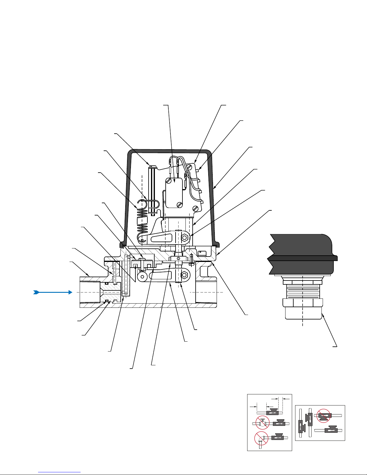
MICROSWITCH (2 REQ’D FOR QD-1)
SPDT 15A 125/250 VAC
DRY CIRCUIT MICROSWITCH SPDT 0.1A 125 VAC (OPTIONAL)
3 WIRES W/ CRIMPED TERMINALS (6 TERMINALS IN QD-1)
2 SCREWS, NUTS, AND LOCKWASHERS
LEADSCREW
LEADSCREW NUT
SPRING
DIAPHRAGM SCREW
DIAPHRAGM WASHER
DIAPHRAGM PISTON
ORIFICE PIN
BODY CASTING
BRACKET
TERMINAL STRIP (NOT SUPPLIED WITH QD-1)
2 SCREWS, NUTS, AND LOCKWASHERS
COVER CASTING
COVER SEAL AND SCREW ASSEMBLY
STANDOFF
2 SCREWS & LOCKWASHERS
UPPER BEAM ASSEMBLY
SCREW, NUT & LOCKWASHERS
LID CASTING
8 SCREWS & LOCKWASHERS
O-RING
ORIFICE
DIAPHRAGM RING
4 SCREWS & LOCKWASHERS
ROLLING DIAPHRAGM
GASKET
FEEDTHRU SHAFT ASSEMBLY
LOWER BEAM ASSY
SCREW, NUT & LOCKWASHER
CLAMP WASHER
3 SCREWS & LOCKWASHERS
2D
5D
PART SIDE VIEW
CABLE CONNECTOR
TURBULENT
FLOW REDUCTION
PARTS LIST
FLUID FLOW SWITCH
ULTRA RELIABLE SINCE 1956 P. 1
MOUNT IN
THREE POSITIONS
HARWIL CORPORATION
541 KINETIC DRIVE, OXNARD, CA 93030
MODE L Q -1
TEL: (805) 988-6800 FAX: (805) 988-6804
EMAIL: HARWIL@HARWIL.COM
Q -1, Q D -1
INSTALLATION INSTRUCTIONS
The gasket seal located between the main body casting and the lid casting is a cork-rubber composition which is subject to a slight creep for a short period after application of initial clamping load. All
gaskets are properly clamped before shipment; however, during shipping and storage, the gasket may
compress, allowing the body-lid clamp bolts to become slightly loose. Tighten these bolts before assembling the flow switch in your system.
No further creep of the gasket will occur after the second tightening. The Q-1 fluid flow switch is supplied with tapped holes for standard ½” pipe. Insert in line with arrow on the side of the casting pointed in the direction of flow.
NOTE: Care should be exercised to prevent pipe thread sealant (putty, Teflon tape, etc.) from entering
the flow switch and restricting flow through the calibrated orifice.
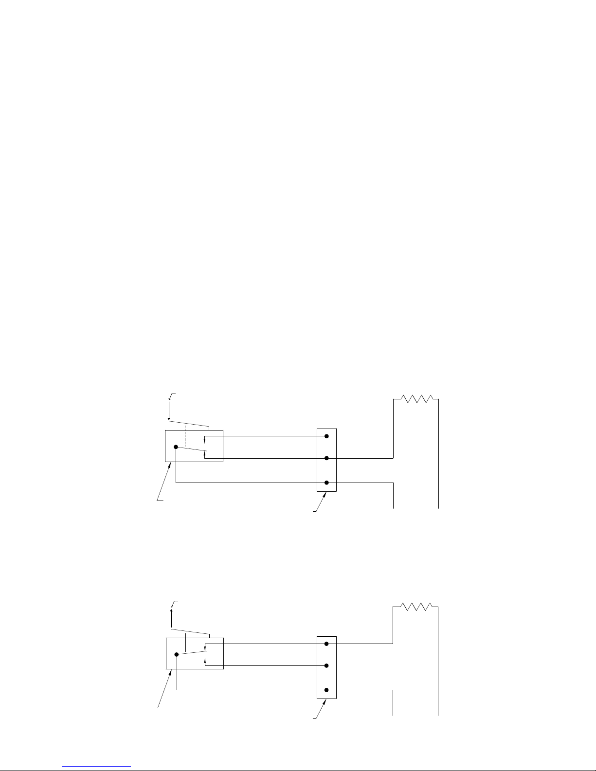
ELECTRICAL WIRING
FIGURE 1: Wiring schematic for power applied to load when flow is GREATER than the set point (power to load interrupted when flow is LESS than set point).
INCREASING FLOW MOVES
ACTUATOR IN DIRECTION SHOWN
NC (ORANGE)
NO (WHITE)
COM (BLACK)
MICROSWITCH
(HOT)
TERMINAL STRIP
LOAD
LINE
FIGURE 2: Wiring schematic for power applied to load when flow is LESS than the set point (power to
load interrupted when flow is GREATER than set point).
DECREASING FLOW MOVES
ACTUATOR IN DIRECTION SHOWN
LOAD
MICROSWITCH
NC (ORANGE)
NO (WHITE)
COM (BLACK)
ULTRA RELIABLE SINCE 1956P. 2
TERMINAL STRIP
(HOT)
LINE
MODE L Q -1
Q -1, Q D -1
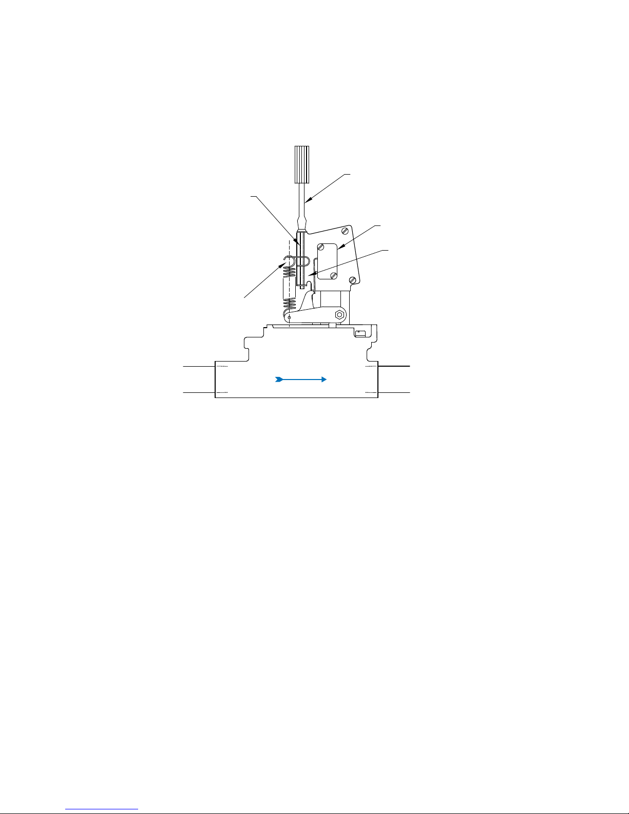
Q-1 FLOW SWITCH OPERATIONAL ADJUSTMENT
REMOVE COVER
LEADSCREW
BEST ADJUSTMENT POINT (CENTERED)
HARWIL CORPORATION
541 KINETIC DRIVE, OXNARD, CA 93030
TEL: (805) 988-6800 FAX: (805) 988-6804
EMAIL: HARWIL@HARWIL.COM
ADJUST LEADSCREW
MICROSWITCH
SPRING POSITION WHEN DELIVERED
SWITCH POINT ADJUSTMENT
1. Remove cover.
2. Adjust fluid flow in system to desired rate WITHOUT regard to Q-1 switch point setting.
3. The switch point adjusting mechanism consists of an adjusting screw, a “U” shaped leadscrew nut,
and a helical spring.
CLOCKWISE rotation of the adjusting screw changes the microswitch actuation point toward HIGHER
flow rates.
NOTES: All Q-1 units are factory set at the lower end of the flow range, e.g. the adjusting screw is set
at the low flow counter-clockwise position.
The leadscrew nut locks the adjusting screw in position, maintaining the flow switch set point under all
environmental conditions.
4. Turn the adjusting screw in a clockwise direction until the microswitch is actuated, while maintaining
the desired fluid flow rate in the system. Turn the adjusting screw TWO (2) additional turns in the
clockwise direction and then slowly back off in a counter-clockwise direction, until the microswitch
is again actuated. The Q-1 flow switch is now set for maximum sensitivity for detecting small flow
changes.
5. When set for maximum sensitivity (100% point) as described above, flow turbulence may cause
rapid on/off switching (dithering) of the microswitch contacts, resulting in reduced switch contact life
ULTRA RELIABLE SINCE 1956 P. 3
 Loading...