

Harwil L-30 Installation And Operating Instruction Manual
MODEL L-30
L-30N, L-30R, L-30CR, VERTICAL L-30NV, L-30CRV
INSTALLATION AND OPERATING INSTRUCTIONS
HARWIL CORPORATION
541 KINETIC DRIVE, OXNARD, CA 93030
TEL: (805) 988-6800 FAX: (805) 988-6804
EMAIL: HARWIL@HARWIL.COM
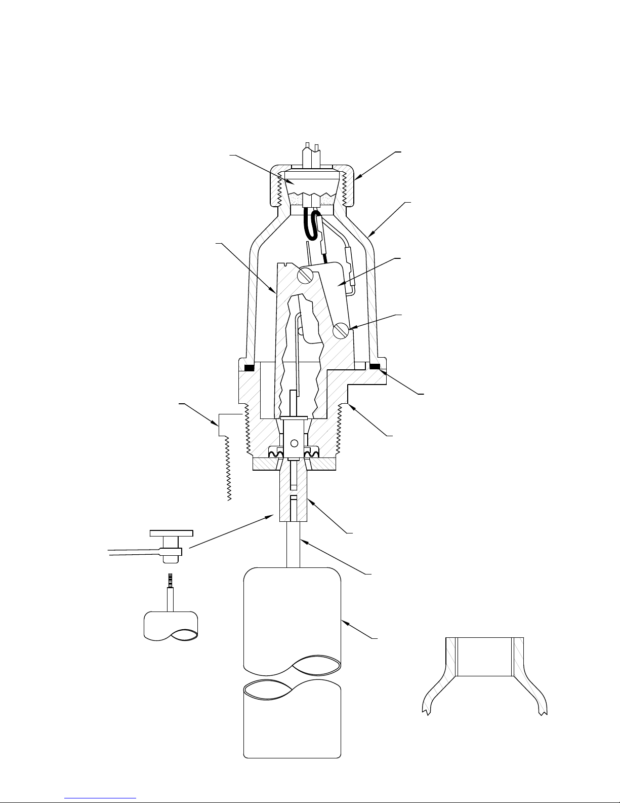
GROMMET ‘A’
GROMMET ‘AA’
GROMMET ‘B’
GROMMET ‘C’
MICROSWITCH BRACKET
1¼” x 1” BUSHING
STRAIN RELIEF NUT
COVER
4 RETAINING SCREWS
(NOT SHOWN)
MICROSWITCH 15A SPDT
WITH 2 SLIP-ON TERMINALS
DRY CIRCUIT SPDT 0.1A 125 VAC
MICROSWITCH
2 SCREWS
2 NUTS
SPLIT LOCKWASHERS
1 PLAIN WASHER
O-RING
BODY COMPLETE WITH
A) SEAL SHAFT
B) DIAPHRAGM
C) DIAPHRAGM WASHER
D) FEED THRU SHAFT
E) PIVOT PIN
F) CAP (SONICALLY WELDED)
NOTE: SEAL SHAFT MUST BE GRIPPED DURING
REMOVAL OR INSERTION OF FLOAT SHAFT.
FAILURE TO GRIP SHAFT SECURELY WILL CAUSE
LEAKAGE OF INTERNAL ELASTOMER SEAL.
GRIPPING FLATS
FLOAT SHAFT
FLOAT SHAFT
EXTENDED LENGTH
FLOAT
‘F’ COVER TO SUIT CUSTOMER
SUPPLIED FITTING FOR ½”
FLEXIBLE CONDIUT
ULTRA RELIABLE SINCE 1956 P. 1
HARWIL CORPORATION
¼”
541 KINETIC DRIVE, OXNARD, CA 93030
MODEL L-30
L-30N, L-30R, L-30CR, VERTICAL L-30NV, L-30CRV
TEL: (805) 988-6800 FAX: (805) 988-6804
EMAIL: HARWIL@HARWIL.COM
INSTALLATION AND OPERATING INSTRUCTIONS
The L-30 liquid level switch is supplied with a 1½” or 1¼” x 1” bushing, threaded in place with 2 to
3 wraps of Teflon tape, which must be intact or renewed if the bushing and switch are separated before assembly in the tank. Care must be taken when threading the bushing into plastic or metal fittings.
Apply a minimum of 2 to a maximum of 3 wraps of Teflon tape to the threads of the bushing–this is
especially important if the unit is to be used in metal fittings where coarse METAL THREADS could gall
plastic if not lubricated. The plastic bushing CAN BE CRACKED if the main body of the flow switch is
tightened into it FIRST. Cracking will not occur if the bushing is FIRST tightened into the pipe or tank fitting and THEN the L-30 body is tightened into the bushing.
Thus:
1. Teflon tape thread and tighten plastic bushing into pipe or tank fitting.
2. Teflon tape thread and tighten L-30 switch into a PLASTIC bushing by applying a wrench to
the hexagonal section. Repeat steps 1 and 2 until the ARROW on the body points UPWARD
and threads are leak tight.
Plumber’s tools, such as pipe wrenches, are not recommended. If possible, use a “rigid” type wrench
where the smooth jaws closely fit the hexagonal section.
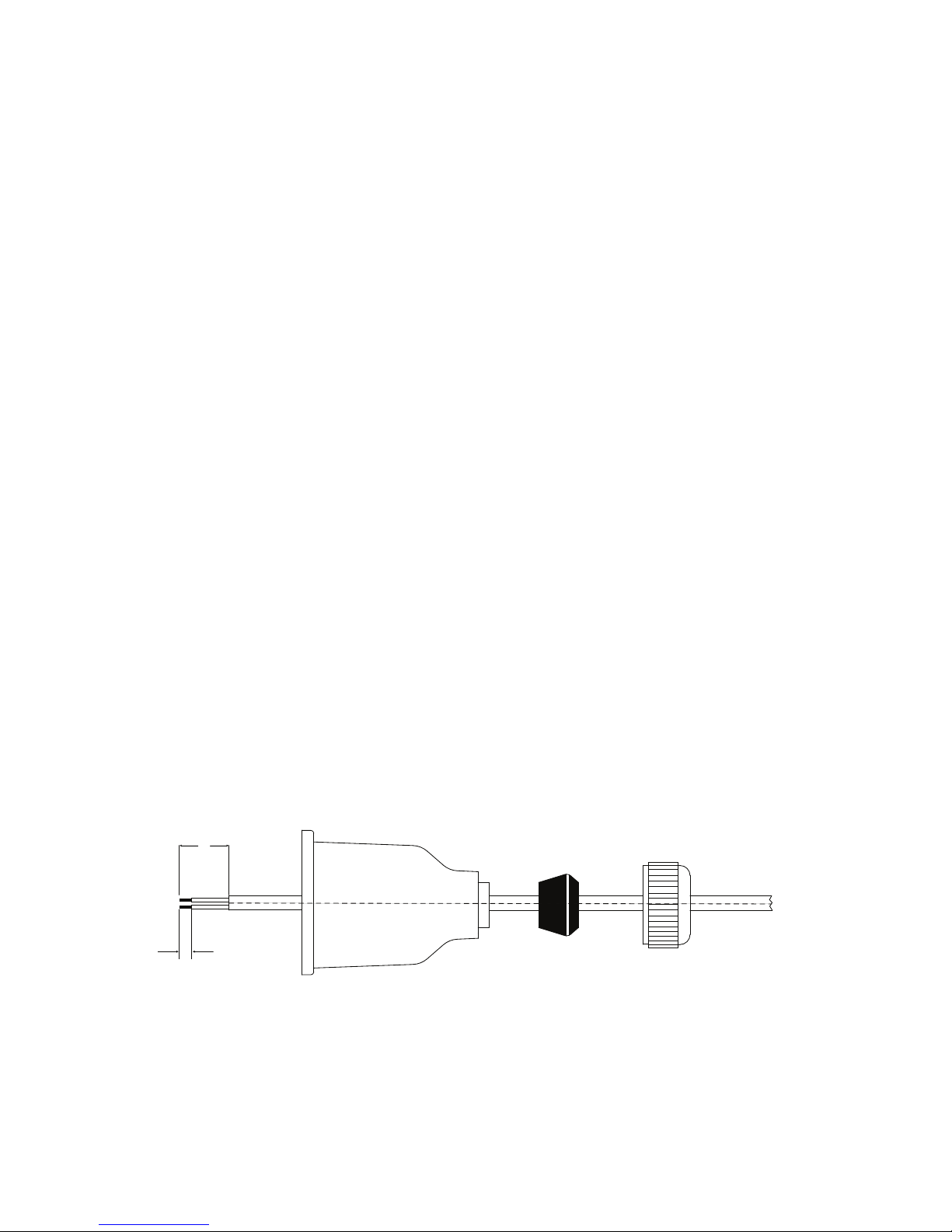
ELECTRICAL WIRING
1. Remove the gland nut, grommet, and switch cover.
2. Strip the outer jacket of the electrical cord back approximately 1¼”. Strip the insulation from individual conductors back approximately ¼”.
3. Slip on terminals are supplied with each switch. Remove from switch terminals and crimp on or solder them to the electrical leads.
4. Feed the electrical cable through the gland nut, grommet, and switch cover as shown.
1¼”
5. Apply slip on terminals to appropriate contacts of the microswitch. Slide the cover down the cable
and fasten it to the body of the switch with the four screws provided. Push the grommet into the
tapered end of the cover. Hold the cable jacket to prevent rotation and thread the gland nut firmly
onto the cover.
ULTRA RELIABLE SINCE 1956P. 2
 Loading...