

Harwil L-21 Installation And Operating Instructions Manual
MODEL L-21
INSTALLATION AND OPERATING INSTRUCTIONS
HARWIL CORPORATION
541 KINETIC DRIVE, OXNARD, CA 93030
TEL: (805) 988-6800 FAX: (805) 988-6804
EMAIL: HARWIL@HARWIL.COM
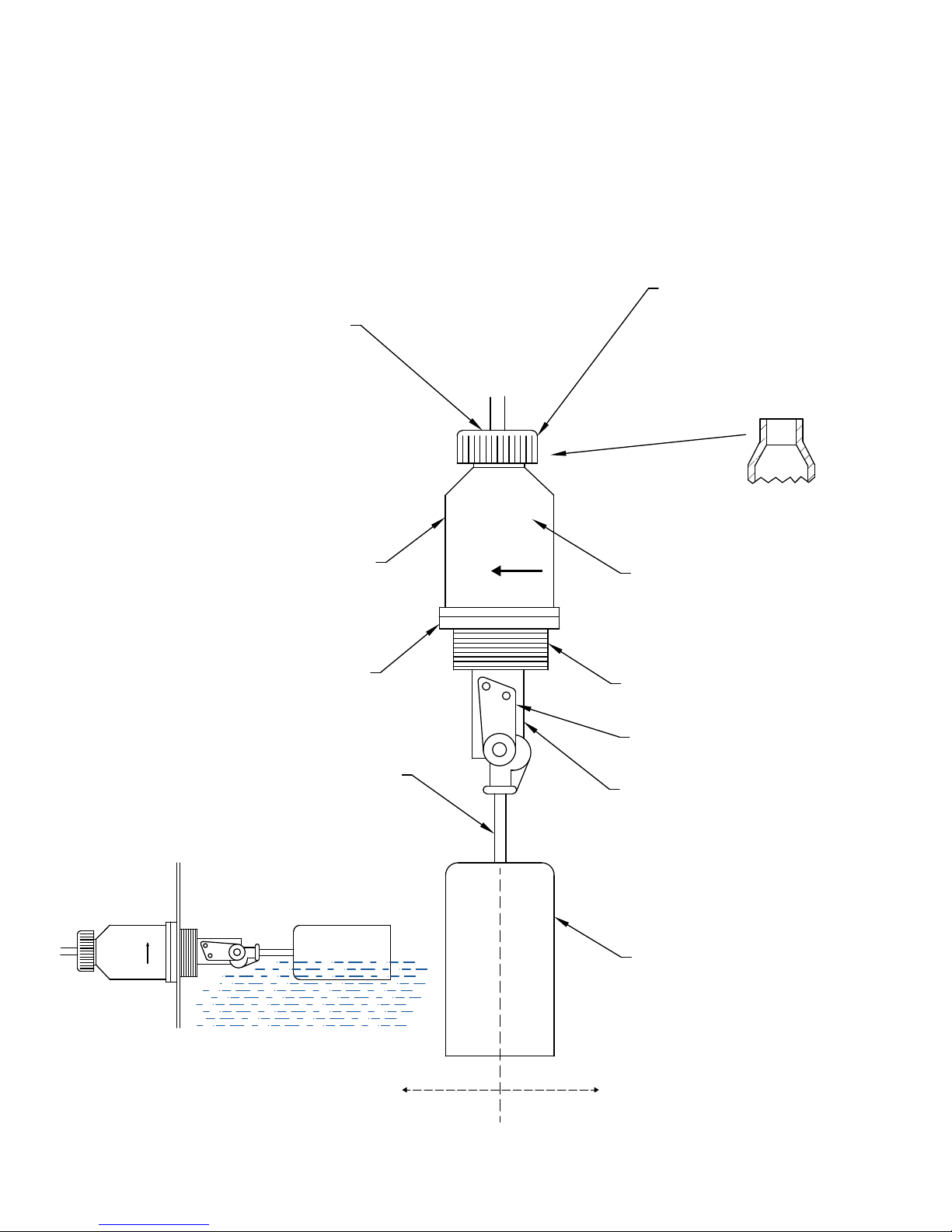
CABLE GROMMET 'A'
CABLE GROMMET 'AA'
CABLE GROMMET 'B'
CABLE GROMMET 'C'
COVER, INCLUDING O-RING
SEAL, RETAINING SCREWS
THREADED BODY COMPLETE,
INCLUDING SWITCH BRACKET
FLOAT SHAFT
FLOAT SHAFT
EXTENDED LENGTH
OR
UP
STRAIN RELIEF NUT
½” INTERNAL THREADS FIT
STANDARD ½” ELECTRICAL
AND PLUMBING FITTINGS
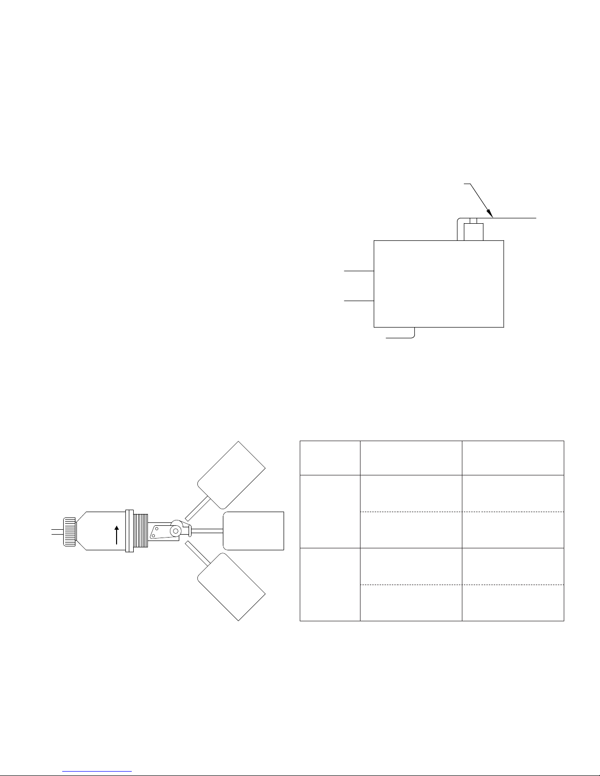
‘F’ COVER
INTERNAL 15A MICROSWITCH
1¼” NPT THREAD
PIVOT SUPPORT
MAGNET HOUSING
10652-12-1 1.0” DIFF.
10652-12-2 2.0” DIFF.
10652-12-3 3.0” DIFF.
10652-12-5 5.0” DIFF.
UP
FLOAT
FLOAT DOWNFLOAT UP
ULTRA RELIABLE SINCE 1956 P. 1
MODEL L-21
INSTALLATION AND OPERATING INSTRUCTIONS
1. If the shipping container and contents are received damaged, immediately call the shipping
company for damage inspection and file the appropriate report, sending a copy to Harwil Corp.
for product replacement and insurance adjustment.
2. If the contents are not damaged, inspect the units
received against the packing list and the original
purchase order. If incorrect units are received,
call Harwil Corp. immediately for resolution of
the problem.
3. Check for damage or scuffing on the Teflon
tape applied to the 1¼” NPT threads of the
switch body. Re-tape as required with 2 to 3 layers wound clockwise (looking at the end of the
threaded body with the float toward the viewer).
4. Remove the cover and check switch action with a
multimeter while moving the float up and down.
HARWIL CORPORATION
541 KINETIC DRIVE, OXNARD, CA 93030
TEL: (805) 988-6800 FAX: (805) 988-6804
EMAIL: HARWIL@HARWIL.COM
ACTUATION ARM
NORMALLY CLOSED (NC)
NORMALLY OPEN (NO)
COMMON
FLOAT UP/DOWN CONFIGURATION
FLOAT
POSITION
UP
UP
DOWN
5. Replace the domed cover on the unit and insert the float through the 1¼” NPT hole in the tank.
Mate the switch body threads with tank threads and tighten with an appropriate wrench until the
thread joint is leak-tight and the arrow on the cover label is pointing vertically upward.
NOTE: Model L-21 can be supplied with 1½” x 1¼” or larger reducer bushings as required to fit existing
large holes in a tank wall.
6. Remove the cover and wire as indicated on page 3.
MULTIMETER
CONNECTION METER READING
COMM. AND NO
TERMINALS
COMM. AND NC
TERMINALS
COMM. AND NO
TERMINALS
COMM. AND NC
TERMINALS
CONTINUITY
OPEN CIRCUIT
OPEN CIRCUIT
CONTINUITY
ULTRA RELIABLE SINCE 1956P. 2
MODEL L-21
HARWIL CORPORATION
541 KINETIC DRIVE, OXNARD, CA 93030
TEL: (805) 988-6800 FAX: (805) 988-6804
EMAIL: HARWIL@HARWIL.COM
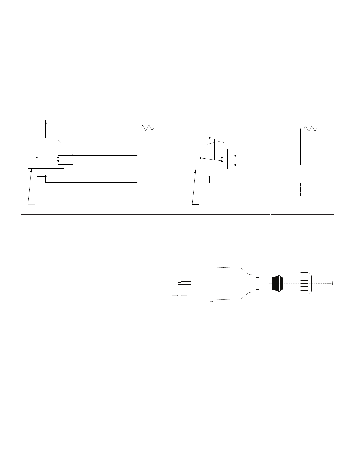
LOW LIQUID LEVEL ALARM
Fig 1: Wiring schematic for power applied to load when
liquid level is less than set point (power to load interrupted
when level increases to above set point).
Decreasing liquid level moves actuator in direction shown.
LOAD
NC
HIGH LIQUID LEVEL ALARM
Fig 2: Wiring schematic for power applied to load when
liquid level is greater than set point (power to load interrupted when level decreases to below set point).
Increasing liquid level moves actuator in direction shown.
LOAD
NC
NO
NO
COM
MICROSWITCH
Microswitch actuation point may be monitored by an audible click or with an ohmmeter before connecting line power to the
switch terminals or by monitoring the voltage supplied to the load through the microswitch.
(HOT)
LINE
COM
MICROSWITCH
(HOT)
LINE
* Pump Up wiring diagram same as low level alarm shown in Fig. 1
* Pump Down wiring diagram same as high level alarm shown in Fig. 2
* Electrical Wiring (Strain Relief Grommet):
Step 1) Remove the gland nut, grommet, and switch cover.
Step 2) Strip the outer jacket of the electrical cord back
approximately 1¼” (inches). Strip insulation from
individual conductors back approximately ¼”
(inch).
Step 3) Slip-on terminals are supplied with each switch.
Remove from switch terminals and crimp on or solder to electrical leads.
Step 4) Feed the electrical cable through the strain relief nut, grommet, and switch cover.
Step 5) Apply slip-on terminals to appropriate contacts of microswitch. Slide cover down the cable and fasten it to the body
of the switch with four (4) screws provided. Slide grommet down the cable and push the grommet into the tapered
end of the cover. Hold the cable jacket to prevent rotation and thread gland nut firmly onto cover.
* Electrical Wiring (‘F’ Cover):
Step 1) Remove switch cover.
Step 2) Strip the outer jacket of the electrical cord back
approximately 1¼” (inches). Strip insulation from individual conductors back approximately ¼” (inch).
Step 3) Slip-on terminals are supplied with each switch. Re-
move from switch terminals and crimp on or solder
to electrical leads.
Step 4) Thread user supplied ½” flexible conduit fitting into
½” female thread on end of cover. Feed electrical
1¼”
¼”
cable through conduit fitting.
Step 5) Apply slip-on terminals to appropriate male spade
contacts on microswitch. Slide cover down cable
and fasten to body of switch with four (4) screws
provided. Be sure to install the “O” ring between
the body and cover. Connect flexible ½” metal or
plastic conduit-to-conduit fitting on end of cover per
standard procedure.
ULTRA RELIABLE SINCE 1956 P. 3
 Loading...