

Page 1
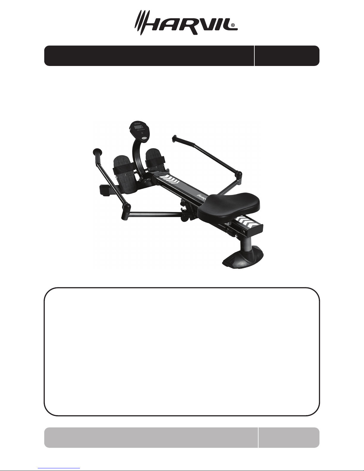
ASSEMBLY MANUAL RM-1
RM-1 1
Hydraulic Resistance
Rowing Machine
The information contained in this manual is subject to change without notice.
We work around the clock and around the globe to ensure that Harvil products
maintain the highest possible quality. However, in the rare instance that your
product is defective or missing parts, contact your retailer to submit parts
requests or warranty claims. Please read the warranty information at the back
of these assembly instructions for further details.
IMPORTANT! PLEASE READ THESE ASSEMBLY INSTRUCTIONS
IN ENTIRETY BEFORE ASSEMBLING YOUR PRODUCT
Thank you for your purchase of this Harvil Product
Page 2
2
SAFETY INSTRUCTIONS
RM-1
1. Save these instructions and ensure that other exercisers read this manual prior to using
the Hydraulic Rowing Machine for the rst time.
2. Read all warnings and cautions posted on the equipment.
3. The Harvil Hydraulic Resistance Rowing Machine should only be used after a thorough
review of the Owner’s Manual. Make sure that it is properly assembled and tightened
before use.
4. We recommend this product to be assembled by 2 people.
5. Keep children away from the Hydraulic Rower. Do not allow children to use or play on
the equipment. Keep children and pets away from the rower when in use.
6. It is recommended that you place this exercise Hydraulic Rower Machine on an
equipment mat.
7. Set up and operate the Harvil Hydraulic Resistance Rowing Machine on a solid level surface.
Do not position the equipment on loose rugs or uneven surfaces.
8. Make sure that adequate space is available for access to and around the Machine.
9. Keep ngers clear of all pinch point when folding and unfolding the equipment.
10. Before using, inspect the equipment for worn or loose components, and securely tighten
or replace any worn or loose components prior to use.
11. Shocks on rowers get HOT during use. To avoid burns, do not touch the shock until it
has time to cool.
12. Consult a physician prior to commencing an exercise program and follow his/her
recommendations in developing your tness program. If at any time during exercise you
fee faint, dizzy, or experience pain, stop and consult your physician.
13. Always choose the workout which best ts your physical strength and exibility level.
Know your limits and train within them. Always use common sense when using the
equipment.
14. Do not wear loose or dangling clothing while using the equipment.
15. Never exercise in bare feet or socks; always wear proper footwear such as running, walking,
or cross training shoes that t well, provide foot support, and feature non-skid rubber soles.
16. Be careful to maintain your balance while using, mounting, dismounting, or assembling
the equipment, loss of balance may result in a fall and serious bodily injury.
17. Do not use the seat to move the equipment. The Seat will move and the Seat Carriage
may pinch your hands or ngers.
18. The equipment should not be used by persons weighing over 250 pounds.
19. The equipment should be used by only one person at a time.
20. The equipment is for consumer use only. It is not for use in public or semipublic facilities.
Page 3
3RM-1
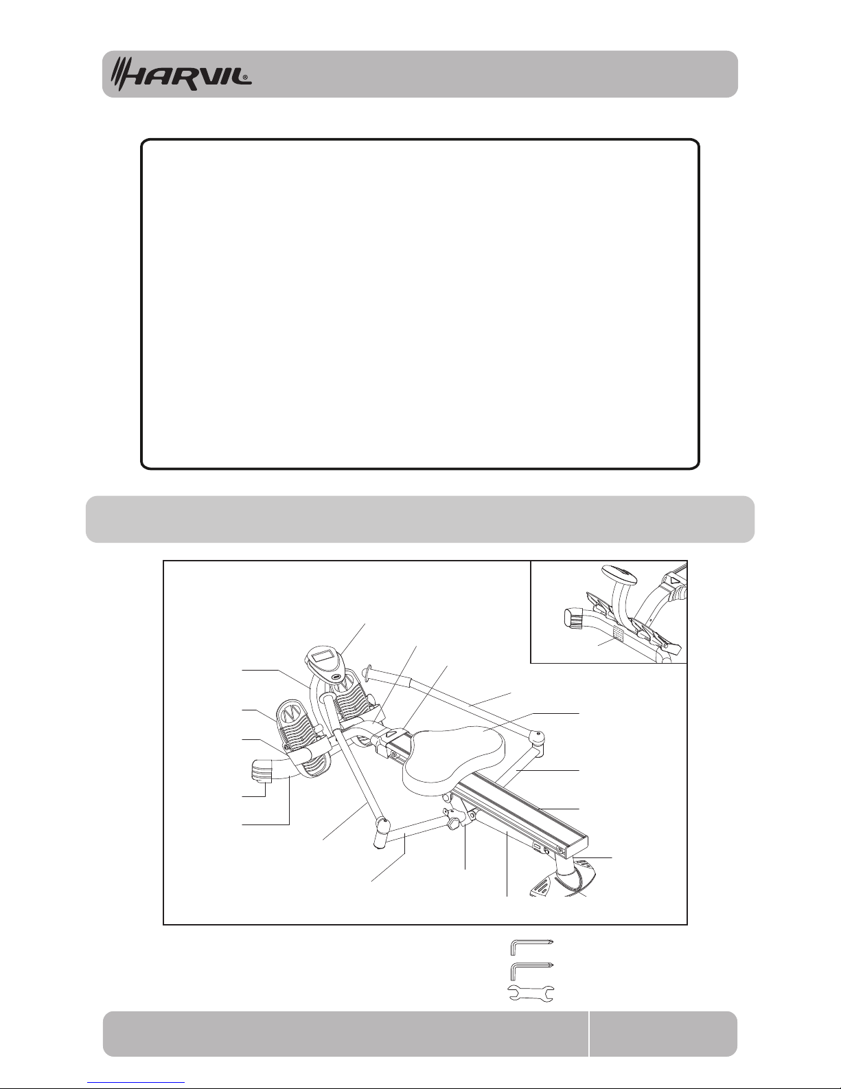
THE FOLLOWING TOOLS ARE REQUIRED FOR ASSEMBLY: Allen Wrench (5mm)
Allen Wrench (5mm)
Wrench (13mm)
Center Beam
Extension Arm
Extension Arm
Pivot Connector
Shock
Rear
Support
Stabilizer
Cap
Seat
Left Handlebar
Right Handlebar
Front Cover
Front Support
Meter
Meter Post
Pedal
Front
Stabilizer
Left
Stand Cap
Warning Label
Pedal Strap
SAFETY INSTRUCTIONS
Exercise can present a health risk. Consult a physician before beginning any
exercise program with this equipment. If you feel faint or dizzy, discontinue
use of this equipment immediately. Serious body injury may occur if the
equipment is not assembled and used correctly, or not following the
instructions correctly. This is especially important if you are over the age of 35,
have never exercised before, are pregnant, or suer from any health problem.
This product is for home use only. Do not use in institutional or commercial
applications.
Keep others and pets away from the equipment when in use. Always make sure
all bolts and nuts are securely tightened prior to each use. Please follow through
all safety instructions in this manual.
This product contains a chemical known to the State of California to cause
cancer and birth defects or other reproductive harm.
WARNING
PARTS IDENTIFIER
Page 4
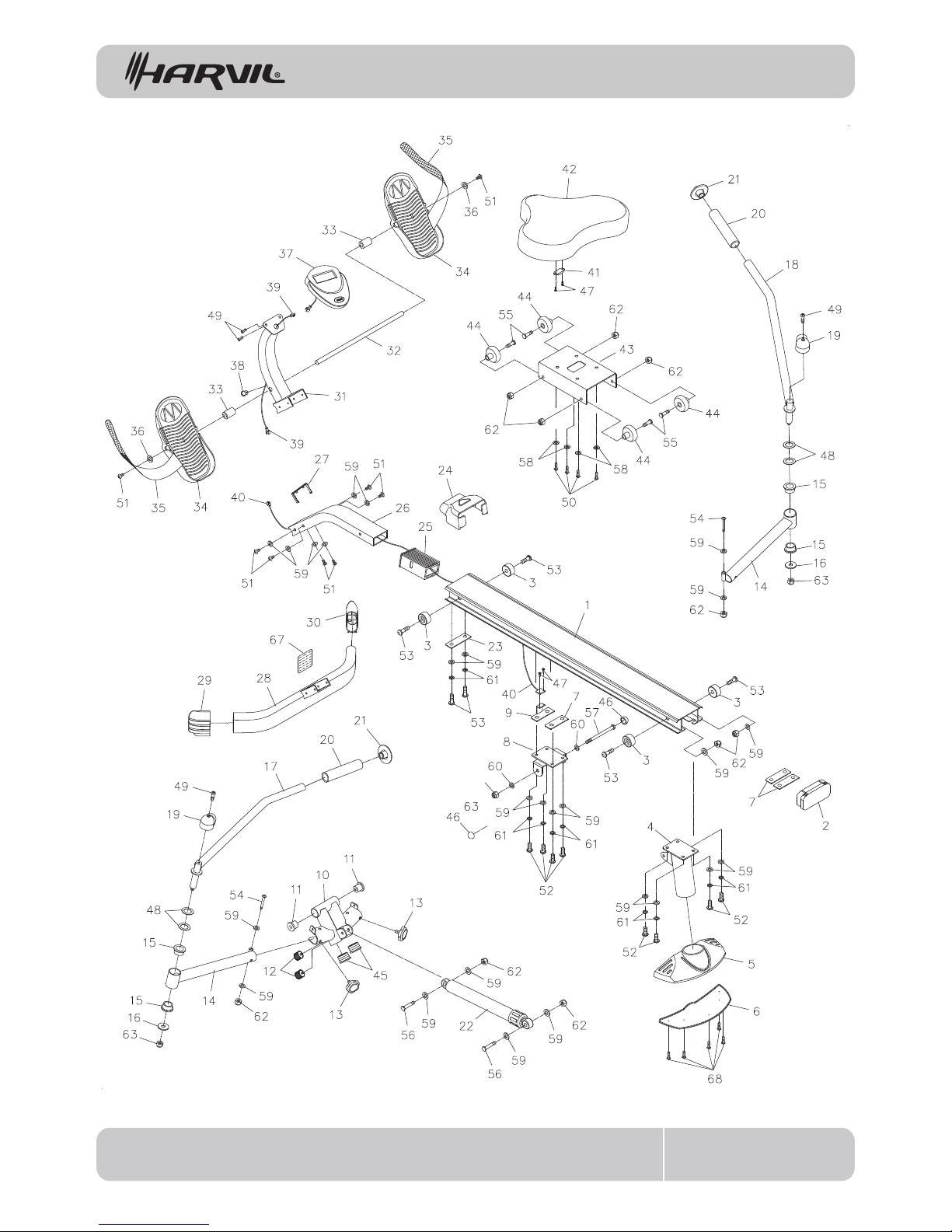
PRODUCT PARTS DRAWING
RM-1 4
FRONT
BACK
Page 5
PARTS LIST
RM-1 5
PART# PART NAME QTY
1
2
3
4
5
6
7
8
9
10
11
12
13
14
15
16
17
18
19
20
21
22
23
24
25
26
27
28
29
30
31
32
33
34
35
36
37
38
39
40
41
42
73
44
45
46
47
Center Beam
Center Beam Cap
Seat Stopper
Rear Support
Stabilizer Cap
Stabilizer Pad
Threaded Support Plate
handlebar Support
Sensor Support Plate
Pivot Connector
Pivot Bushing
Bumper Knob
Locking Knob
Extension Arm
Exension Arm Bushin
Large Washer (M12)
Left Handlebar
Right Handlebar
Securing Cap
Foam Grip
Handlebar Cap
Shock
Support Plate
Front Cover
Sleeve
Front Support
Support Ring
Front Stabilizer
Left Stand Cap
Right Stand Cap
Meter Post
Pedal Shaft
Pedal Spacer
Pedal
Pedal Strap
Large Washer (M8)
Meter
Grommet
Extension Wire
Sensor Wire
Magnet
Seat
Seat Carriage
Roller
Round Plug (25mm)
Nut Cap (M10)
Screw, Round Head (M2.9 x 10mm)
1
1
4
1
1
1
3
1
1
1
2
2
2
2
4
2
1
1
2
2
2
1
1
1
1
1
1
1
1
1
1
1
2
2
2
2
1
1
1
1
1
1
1
4
2
2
4
Page 6
RM-1 6
PART# PART NAME QTY
48
49
50
51
52
53
54
55
56
57
58
59
60
61
62
63
64
65
66
67
68
Wave Washer (ø20 x ø23.5 x 0.5mm thick)
Screw, Round Head (M5 x 0.8 x 12mm)
Bolt, Round Head (M6 x 1 x 15mm)
Bolt, Button Head (M8 x 1.25 x 15mm)
Bolt, Button Head (M8 x 1.25 x 20mm)
Bolt, Button Head (M8 x 1.25 x 25mm)
Bolt, Button Head (M8 x 1.25 x 50mm)
Bolt, Hex Head (M8 x 1.25 x 30mm)
Bolt, Hex Head (M8 x 1.25 x 41mm)
Bolt, Hex Head (M10 x 1.5 x 120mm)
Washer (M6)
Washer (M8)
Washer (M10)
Spring Washer (M8)
Nylon Nut (M8 x 1.25)
Nylon Nut (M10 x 1.5)
Allen Wrench (5mm)
Wrench (13mm)
Owner’s Manual
Warning Label
Screw, Round Head (M3.5 x 15mm)
4
4
4
8
8
6
2
4
2
1
4
26
2
10
10
3
2
1
1
1
5
PARTS LIST
Page 7
7
HARDWARE IDENTIFICATION CHART
RM-1
length
length
mm.
in.
INCHES
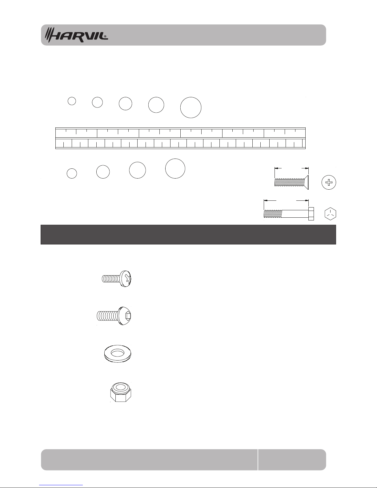
This chart is provided to help identify the fasteners used in the assembly process. Place the washers or
the ends of the bolts or screws on the circles to check for the correct diameter. Use the small scale to
check the length of the bolts and screws.
NOTICE: The length of all bolts and screws, except those with flat
heads, is measured from below the head to the end of the bolt
or screw. Flat head bolts and screws are measured from the
top of the head to the end of the bolt or screw.
After unpacking the unit, open the hardware bag and make sure that you have all the following
fasteners. Some fasteners may be already attached to the parts.
MILLIMETERS
0 10 20 30 40 50 60 70 80 90 100 110 120 130 140 150
0 1/2 1/2 1/2 1/2 1/2 1/21
2 3 4 5 6
6 8 10 12
3/16" 1/4" 5/16" 3/8" 1/2"
Part No. and Description Qty
36 Large Washer (M8) 2
59 Washer (M8) 8
51 Bolt, Button Head (M8 x 1.25 x 15mm) 8
53 Bolt, Button Head (M8 x 1.25 x 25mm) 2
49 Screw, Round Head (M5 x 0.8 x 12mm) 2
62 Nylon Nut (M8 x 1.25) 2
Page 8
8
ASSEMBLY INSTRUCTIONS
RM-1
Place all parts from the box in a cleared area and position them on the oor in front of you. Remove
all packing materials from your area and place them back into the box. Do not dispose of the packing
materials until assembly is completed. Read each step carefully before beginning.
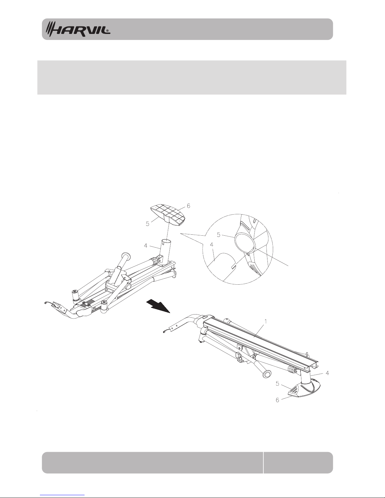
STEP 1
Lay the Main Frame Assembly on the oor as shown in the illustration. Now refer to inset drawing A. Make
sure the Key Rib in the STABILIZER CAP(5) aligns with the slot in the REAR SUPPORT(4), then press the
STABILIZER CAP(5) onto the REAR SUPPORT(4). Turn the Main Frame Assembly to the normal upright
position and make sure the STABILIZER PAD(6) is secured to the STABILIZER CAP(5).
Key Rib
A.
Page 9
9
ASSEMBLY INSTRUCTIONS
RM-1
STEP 2
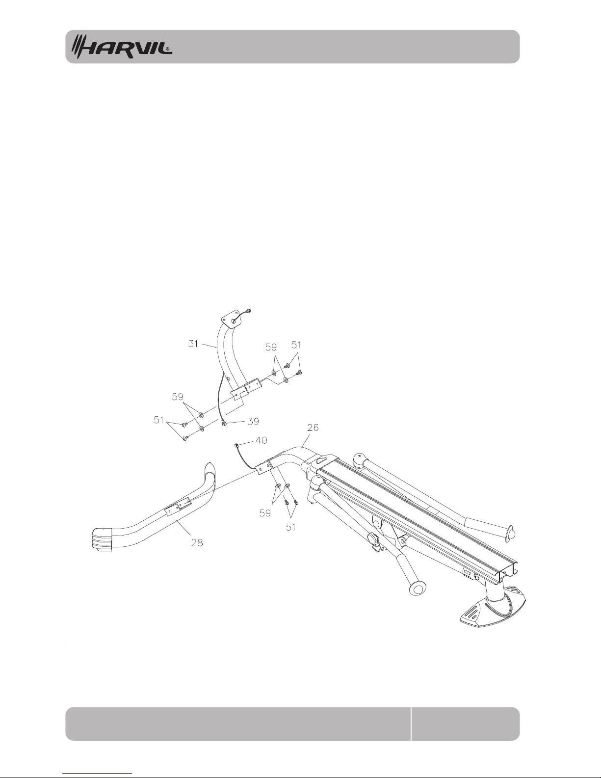
Insert the Bracket on FRONT STABILIZER(28) into the FRONT SUPPORT(26). Attach the METER POST(31)
to the FRONT SUPPORT(28), then bolt the METER POST(31), FRONT SUPPORT(26), and FRONT
STABILIZER(28) together with BUTTON HEAD BOLTS(M8x1.25x15mm)(51) and WASHERS(M8)(59).
Please do not tighten any of these bolts until all six bolts are attached.
NOTE: Be careful not to damage the EXTENSION WIRE(38) when assembling the METER POST(32).
STEP 3
Connect the EXTENSION WIRE(39) to the SENSOR WIRE(40).
Page 10
10
ASSEMBLY INSTRUCTIONS
RM-1
STEP 4
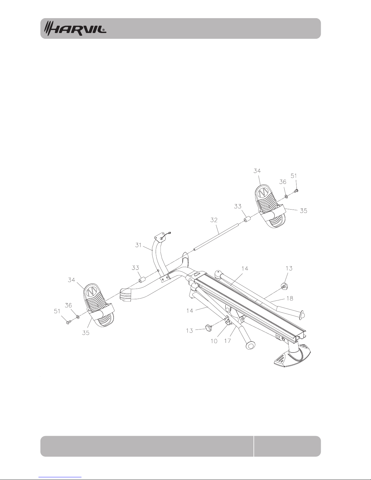
Insert the PEDAL SHAFT(32) through holes located on the METER POST(31). Place a PEDAL SPACER(33)
and a PEDAL(34) onto each end of the PEDAL SHAFT(32) and slide them toward the METER POST(31).
Then secure the PEDALS(34) with BUTTON HEAD BOLTS(M8x1.25x15mm)(51) and LARGE WASHERS
(M8)(36) at both ends of the PEDAL SHAFT(32). You need to use two Allen Wrenches to tighten the
BUTTON HEAD BOLTS(M8x1.25x15mm)(51) at both ends of the PEDAL SHAFT(32) at the same time.
STEP 5
Remove the LOCKING KNOBS(13) from the PIVOT CONNECTOR(10).
Page 11
11
ASSEMBLY INSTRUCTIONS
RM-1
STEP 6
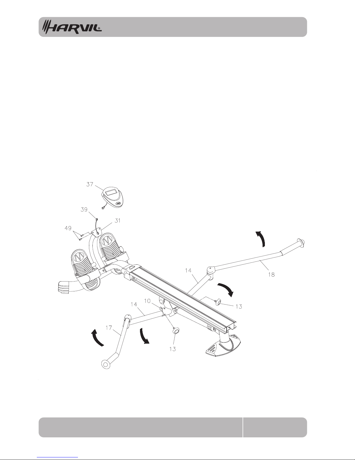
Unfold the HANDLEBARS(17, 18) and the EXTENSION ARMS(14) as shown in the illustration. Attach the
EXTENSION ARMS(14) to the PIVOT CONNECTOR(10) with the LOCKING KNOBS(13).
STEP 7
Install two AA batteries into the METER(37), the batteries are not included. See page 12 for detailed battery
installation instructions. Connect the EXTENSION WIRE(39) to the METER(37). Attach the METER(37) to
the plate on the METER POST(31) with ROUND HEAD SCREWS(M5x0.8x12mm)(49).
Page 12
12
ASSEMBLY INSTRUCTIONS
RM-1
STEP 8
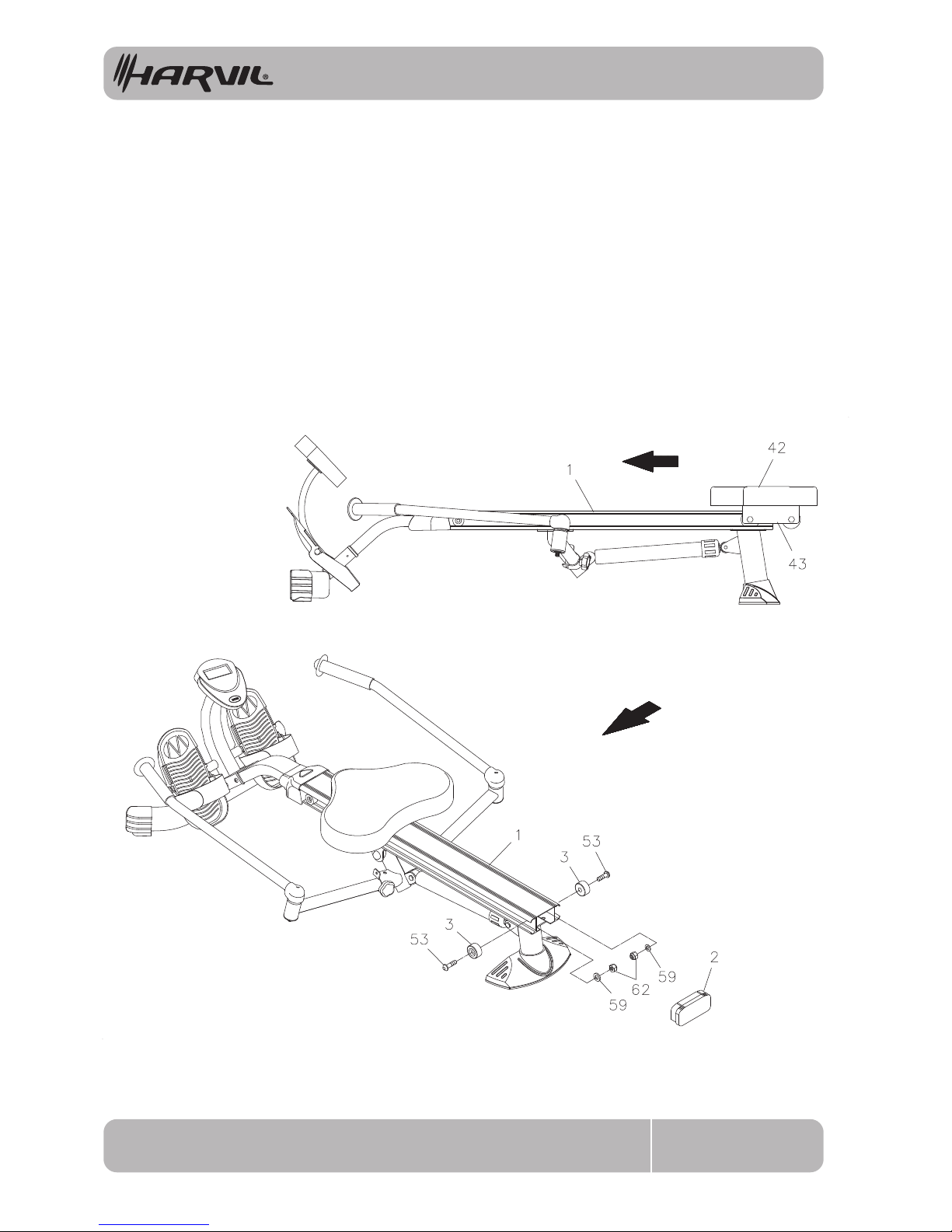
Slide the SEAT ASSEMBLY(42, 43) onto the CENTER BEAM(1). Attach the SEAT STOPPERS(3) to the
back end of the CENTER BEAM(1) with BUTTON HEAD BOLTS(M8x1.25x25mm)(53). Also, please verify
that the other SEAT STOPPERS(3) at the front end of the CENTER BEAM(1) are assembled at the factory.
STEP 9
Press the CENTER BEAM CAP(2) into the back end of the CENTER BEAM(1).
Page 13
13
OPERATIONAL INSTRUCTIONS
RM-1
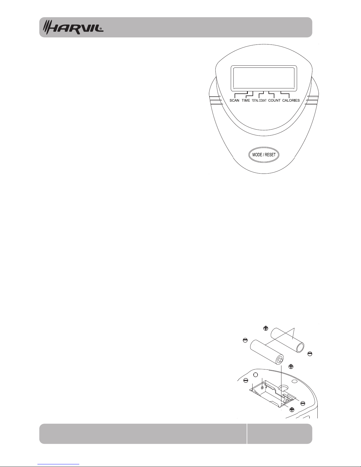
USING THE FITNESS METER
1. Do not mix a new battery with an old battery.
2. Use the same type of battery. Do not mix an alkaline
battery with another type of battery.
3. Rechargeable batteries are not recommended.
4. Ultimate disposal of battery should be handled
according to all state and federal laws and regulations.
5. Do not dispose of batteries in fire.
NOTE:
1. Open the Battery Door on the back of the meter.
2. The meter operates with two AA batteries, the batteries are not
included. Refer to the illustration to install or replace the batteries.
HOW TO INSTALL AND REPLACE BATTERIES:
FUNCTIONS:
Move the seat or press the button.
Automatically shuts off after four
minutes of inactivity.
POWER OFF :
POWER ON :
MODE/RESET BUTTON:
Press to select display functions, including SCAN, TIME,
TOTAL COUNT, COUNT, and CALORIES.
Press and hold for two seconds to reset all functions to
zero, except TOTAL COUNT.
NOTE:
AA Batteries
Automatically scans each function of TIME, TOTAL COUNT, COUNT, and CALORIES
in sequence with change every six seconds.
Displays the elapsed time from one second up to 99:59 minutes.
Displays the total accumulated number of rows you have taken, from zero to 9999
rows. The total accumulated rows is retained when the meter is turned off.
Displays the total number of rows you have taken from zero to 9999 rows.
Displays the calorie burned from zero to 9999 Kcal.
The calorie readout is an estimate for an average user. It should be used only as a
comparison between workouts on this unit.
The TOTAL COUNT will be reset to zero after batteries are removed for battery
replacement or storage of the unit.
SCAN:
TIME:
TOTAL COUNT:
COUNT:
CALORIES:
Page 14
14
OPERATIONAL INSTRUCTIONS
RM-1
LOAD ADJUSTMENT
The safety and integrity designed into the equipment can only be maintained when the
equipment is regularly examined for damage and wear. Special attention should be given to the
following:
1. Pull on the HANDLEBARS(17, 18) and verify that the SHOCK(22) provides tension.
2. Clean the roller tracks in the CENTER BEAM(1) with an absorbent cloth.
3. Verify that all nuts and bolts are present and properly tightened. Replace missing nuts and bolts.
Tighten loose nuts and bolts.
4. It is the sole responsibility of the user/owner to ensure that regular maintenance is performed.
5. Worn or damaged components must be replaced immediately or the equipment removed
from service until repair is made.
6. Keep your equipment clean by wiping it off with an absorbent cloth after use.
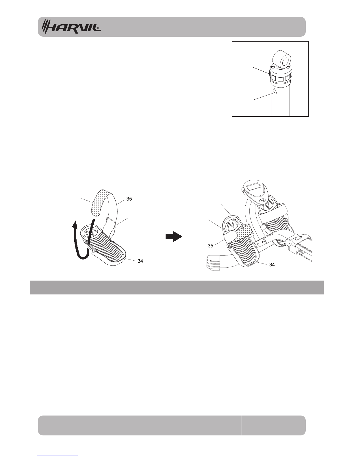
The resistance of the shock can be adjusted by twisting the adjustment
knob at the top of the shock. There are settings from 1 to 12. Setting #1
will provide the lowest resistance. Setting #12 will provide the highest
resistance.
CAUTION: The shock gets HOT after a few minutes of use.
PEDAL STRAP ADJUSTMENT
If you feel it is more comfortable for your workout, you can change to attach the PEDAL STRAP(35) to the
upper position in the PEDAL(34) as shown in illustration 1 below. Run the PEDAL STRAP(35) through the
opening from the bottom of the PEDAL(34), then go through the Steel Ring. Slide the Steel Ring down to
against the PEDAL(34). Run the PEDAL STRAP(35) through the opening in the PEDAL(34) on the other
side from the top as shown in the illustration 1, then make the end of the PEDAL STRAP(35) go up to
attach onto the upper part of the PEDAL STRAP(35) with the Hook & Loop Pad.
Attach the end of the PEDAL STRAP(35) to different position with the Hook & Loop Pad to adjust the length.
Refer to illustration 2.
Adjustment
Knob
Mark
Hook & Loop Pad
Hook & Loop Pad
Steel Ring
1. 2.
End of Pedal Strap
MAINTENANCE
Page 15
15
STORAGE
RM-1
1. To store the equipment, simply keep it in a clean dry place.
2. Grasp the Front and Rear Stabilizer to move the equipment. Do not use the Seat to move the
equipment. The Seat will move and the Seat Carriage may pinch your hand or ngers.
3. To avoid damage to the electronics, remove the batteries before storing the equipment for
one year or more.
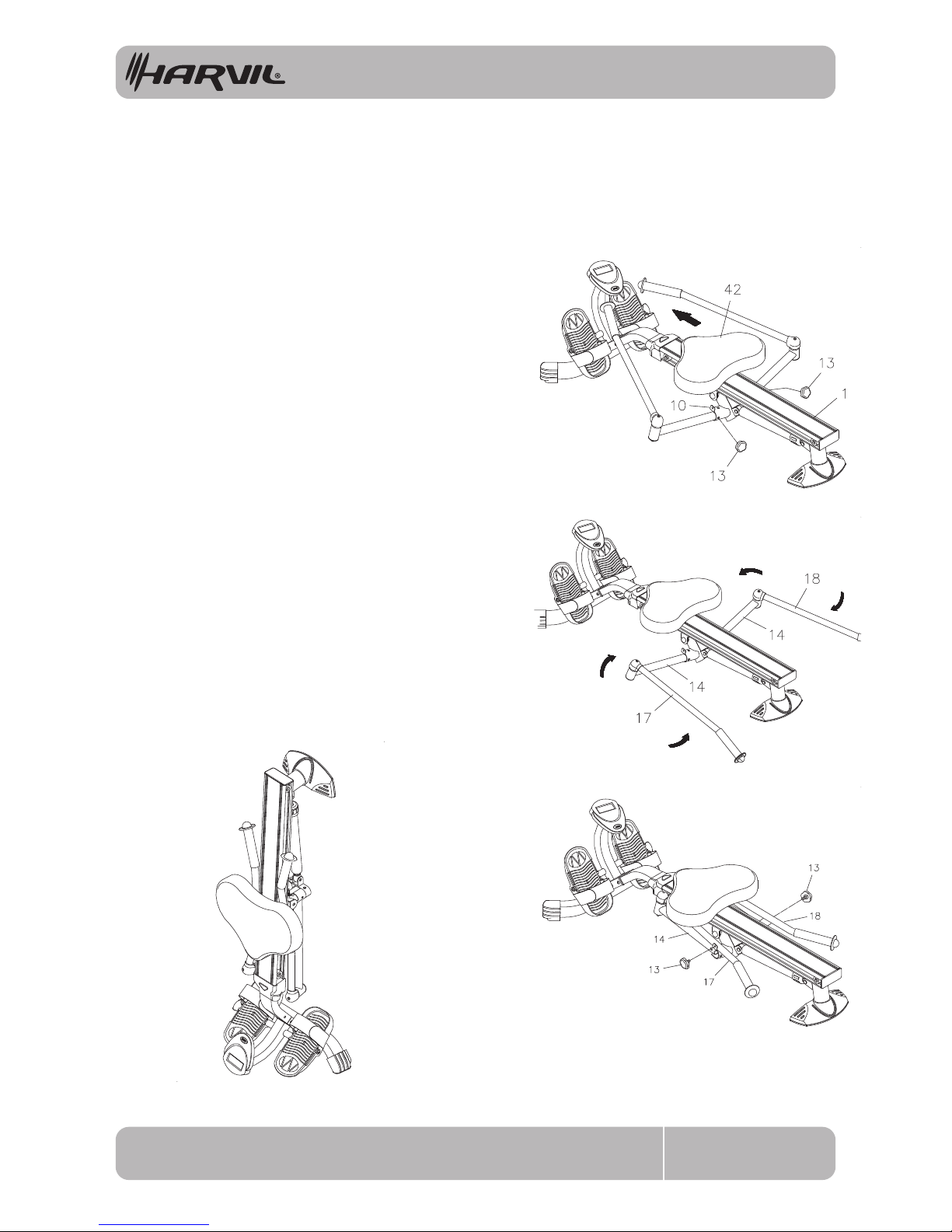
Follow the following process to fold the equipment
as illustrated for easy storage.
A. Slide the SEAT(42) to the front end of the CENTER
BEAM(1). Remove the LOCKING KNOBS(13) from
the PIVOT CONNECTOR(10).
B. Swing the LEFT and RIGHT HANDLEBARS(17, 18)
backward. Then fold the EXTENSION ARMS(14) to
the front.
C. Lock the handlebars in the folded position by
screwing the LOCKING KNOBS(13) onto the
PIVOT CONNECTOR(10). Now, you can store the
equipment in the place you want.
D. Refer to illustration D. You can stand the
equipment on end for storage.
NOTE: Keep ngers clear of all pinch points when
folding and unfolding the equipment.
Folding the Harvil Hydraulic Resistance Rowing Machine
A.
B.
D.
C.
Page 16
16
CONDITIONING GUIDELINES
RM-1
How you begin your exercise program depends on your physical condition. If you have rarely work out
or are overweight, start with mild intensity and increase your workout time gradually. Increase your
workout intensity gradually by monitoring your heart rate while you exercise.
Initially you may only be able to exercise within your target zone for a few minutes; however, your aerobic
capacity will improve over the next six to eight weeks. It is important to pace yourself while you exercise
so you don't tire too quickly.
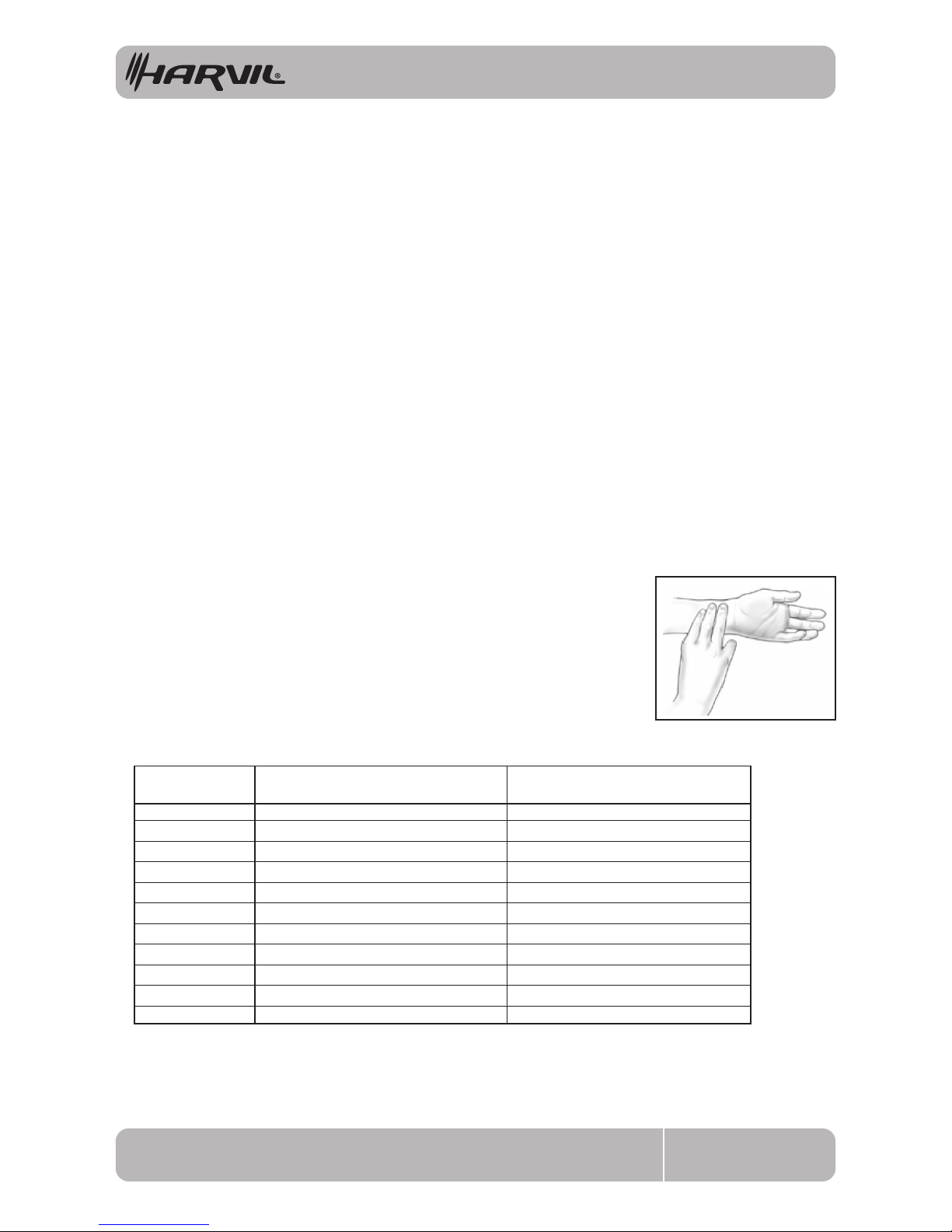
Measure your heart rate periodically during your workout by stopping the
exercise but continuing to move your legs or walk around. Place two or
three fingers on your wrist and take a six second heartbeat count. Multiply
the results by ten to find your heart rate. For example, if your six second
heartbeat count is 14, your heart rate is 140 beats per minute. A six second
count is used because your heart rate will drop rapidly when you stop
exercising. Adjust the intensity of your exercise until your heart rate is at the
proper level.
wrist pulse
Remember to follow these instructions:
• Have your doctor review your training and diet programs.
• Begin your training program slowly with realistic goals that have been set by you and your physician.
• Warm up before you exercise and cool down after you work out.
• Take your pulse periodically during your workout and strive to stay within a range of 60% (lower
intensity) to 90% (higher intensity) of your maximum heart rate zone. Start at the lower intensity, and
build up to higher intensity as you become more aerobically fit.
• If you feel dizzy or lightheaded you should slow down or stop exercising.
To determine if you are working out at the correct intensity, use a heart rate monitor or use the table
below. For effective aerobic exercise, your heart rate should be maintained at a level between 60%
and 90% of your maximum heart rate. If just starting an exercise program, work out at the low end of
your target heart rate zone. As your aerobic capacity improves, gradually increase the intensity of your
workout by increasing your heart rate.
* For cardiorespiratory training benefits, the American College of Sports Medicine recommends
working out within a heart rate range of 55% to 90% of maximum heart rate. To predict the
maximum heart rate, the following formula was used: 220 - Age = predicted maximum heart rate
20 years
25 years
30 years
35 years
40 years
45 years
50 years
55 years
60 years
65 years
70 years
Average Maximum
Heart Rate 100%
Age
110-180 beats per minute
107-175 beats per minute
105-171 beats per minute
102-166 beats per minute
99-162 beats per minute
97-157 beats per minute
94-153 beats per minute
91-148 beats per minute
88-144 beats per minute
85-139 beats per minute
83-135 beats per minute
200 beats per minute
195 beats per minute
190 beats per minute
185 beats per minute
180 beats per minute
175 beats per minute
170 beats per minute
165 beats per minute
160 beats per minute
155 beats per minute
150 beats per minute
Target Heart Rate Zone
(55%-90% of Maximum Heart Rate)
Target Heart Rate Zone Estimated by Age*
Page 17
17RM-1
WARM-UP and COOL-DOWN
Warm-Up
The purpose of warming up is to prepare your body for exercise and to minimize injuries.
Warm up for two to five minutes before strength training or aerobic exercising. Perform activities that
raise your heart rate and warm the working muscles. Activities may include brisk walking, jogging,
jumping jacks, jump rope, and running in place.
Stretching
Stretching while your muscles are warm after a proper warm-up and again after your
strength or aerobic training session is very important. Muscles stretch more easily at these times
because of their elevated temperature, which greatly reduces the risk of injury. Stretches should be held
for 15 to 30 seconds. Do not bounce.
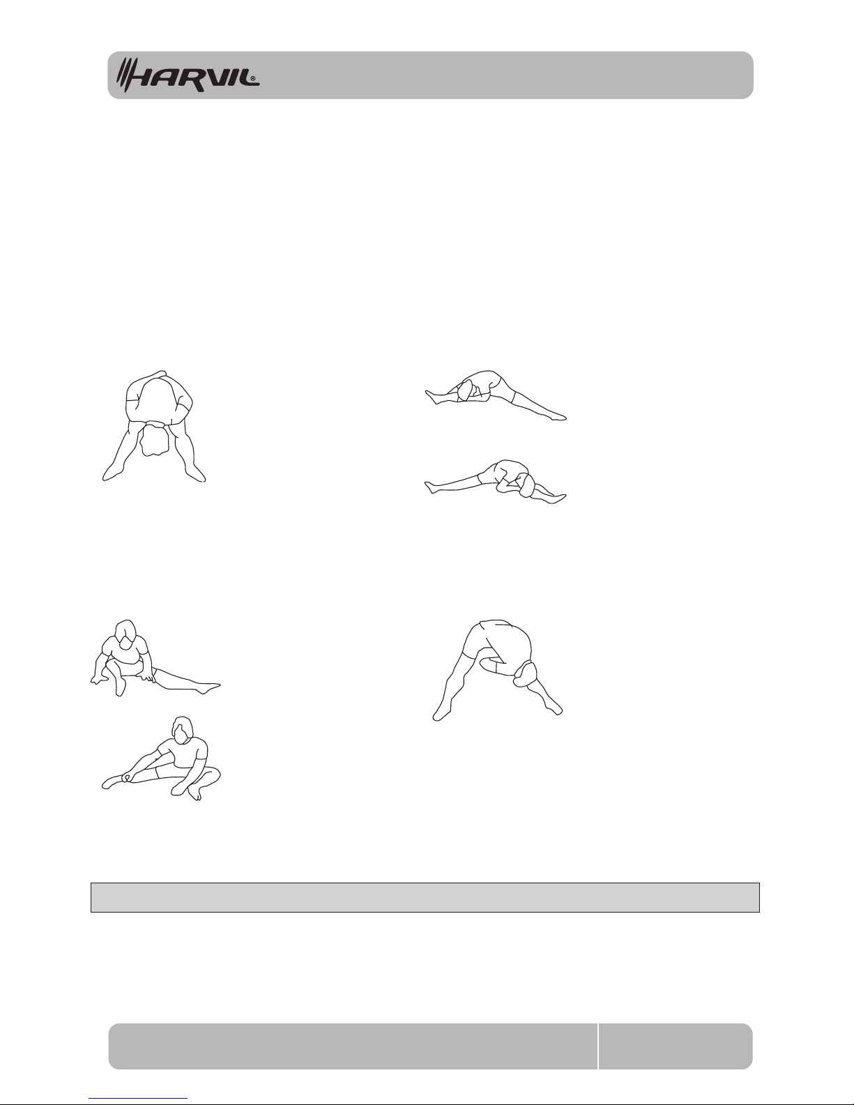
Suggested Stretching Exercises
Remember to always check with your physician before starting any exercise program.
Cool-Down The purpose of cooling down is to return the body to its normal, or near normal, resting
state at the end of each exercise session. A proper cool-down slowly lowers your heart rate and allows
blood to return to the heart. Your cool-down should include the stretches listed above and should be
completed after each strength training session.
Lower Body Stretch
Place feet shoulder-width
apart and lean forward.
Keep this position for 30
seconds using the body as a
natural weight to stretch the
backs of the legs.
DO NOT BOUNCE!
When the pull on the back of
the legs lessens, gradually
try a lower position.
Floor Stretch
While sitting on the floor,
open the legs as wide as
possible. Stretch the upper
body toward the knee on the
right leg by using your arms
to pull your chest to your
thighs. Hold this stretch 10
to 30 seconds.
DO NOT BOUNCE!
Do this stretch 10 times.
Repeat the stretch with the
left leg.
Bent Over Leg Stretch
Stand with feet shoulderwidth
apart and lean forward
as illustrated. Using the
arms, gently pull the upper
body towards the right leg.
Let the head hang down.
DO NOT BOUNCE!
Hold the position a minimum
of 10 seconds. Repeat
pulling the upper body to
the left leg. Do this stretch
several times slowly.
Bent Torso Pulls
While sitting on the floor,
have legs apart, one leg
straight and one knee bent.
Pull the chest down to touch
the thigh on the leg that is
bent, and twist at the waist.
Hold this position at least 10
seconds. Repeat 10 times
on each side.
Page 18
18
180 DAY LIMITED WARRANTY
RM-1
This warranty does not cover defects or damage due to improper installation, alteration, accident or
any other event beyond the control of the manufacturer. Defects or damage resulting from
misuse , abuse or negligence will void this warranty. This warranty does not cover scratching or
damage that may result from normal usage.
This product is not intended for institutional or commercial use; Harvil does not assume any liability
for such use. Institutional or commercial use will void this warranty.
This warranty is nontransferable and is xpressly limited to the repair or replacement of the
defective product. During the warranty period, Harvil shall repair or replace defective parts at no
cost to the purchaser. Shipping charges
and insurance are not covered and are the responsibility of
the purchaser. Labor charges and related expenses for removal, installation or replacement of the
product or components are not covered under this warranty.
Harvil reserves the right to make substitutions to warranty claims if parts are unavailable or obsolete.
Harvil shall not be liable for loss of use of the product or other consequential or incidental costs,
expenses or damages incurred by the consumer of any other use. The user assumes all risk of injury
resulting from the use of this product.
This warranty is expressly in lieu of all other warranties, expressed or implied, including warranties of
any of its representatives assumes any other liability in connection with this product.
All warranty claims must be made through the retailer where the product was originally
purchased. A purchase receipt or other proof of date of purchase will be required to
process all warranty claims. The model number and part numbers found within the
assembly instructions will be required when submitting any parts requests or warranty
claims.
For further warranty information or inquiries, please call 877-800-2299
This Harvil product is warranted to the original purchaser to be free from defects in material or
workmanship for a period of one hundred eighty days from the date of the original retail purchase.
 Loading...