

ASSEMBLY INSTRUCTIONS EB-1
EB-1 1
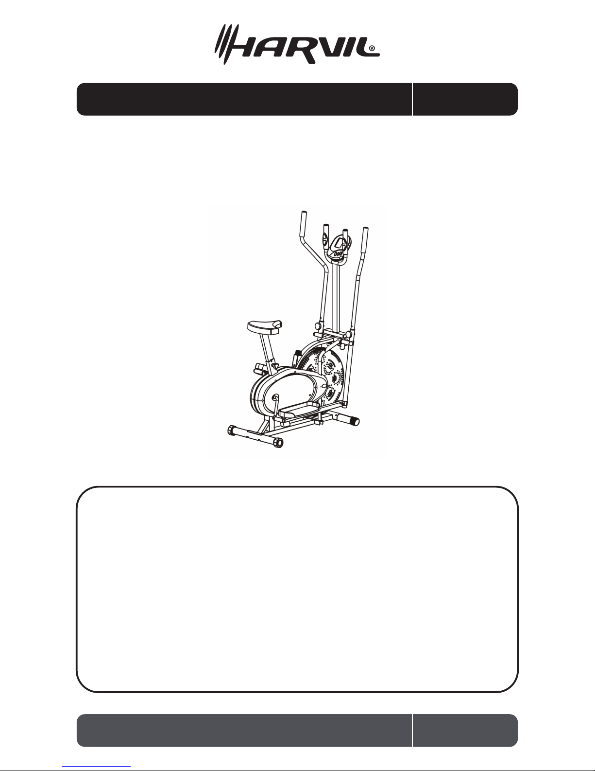
Ellipcal 2 in 1
Exercise Bike
Thank you for your purchase of this Harvil product!
We work around the clock and around the globe to ensure that Harvil products
maintain the highest possible quality. However, in the rare instance that your
product is defective or missing parts, contact your retailer to submit parts
requests or warranty claims. Please read the warranty information at the back
of these assembly instructions for further details.
IMPORTANT! PLEASE READ THESE ASSEMBLY INSTRUCTIONS
IN ENTIRETY BEFORE ASSEMBLING YOUR PRODUCT.
The information contained in this manual is subject to change without notice.
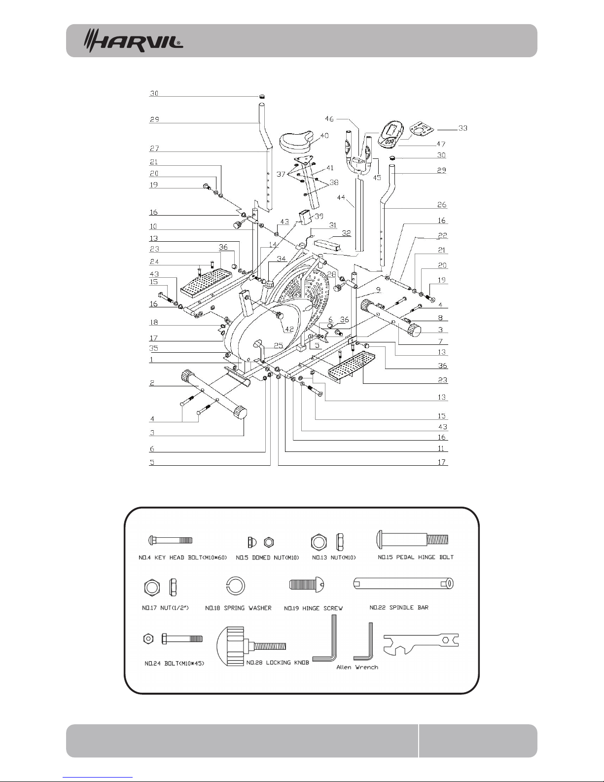
PARTS INDENTIFIER(NOT TO SCALE)
EB-1 2

NO
NA ME
QUA NT IT Y
1
MA IN F R AM E
1
2
R E A R S TA B IL IZ E R
1
3 E ND C A P 4
4 K E Y H E AD B OLT (M10*60) 4
5 DO M E D NU T (M10) 4
6 AR C WAS HE R 4
7 F R O NT S TAB IL IZ E R 1
8 T R A N S P O T TAT I O N W H E E L 2
9 L O WE R HA N DL E B A R ( R IG H T ) 1
10
L O WE R HA N DL E B A R ( L E F T )
1
11
R IG HT P E DA L P O S T
1
12
L E F T P E DA L P O S T
1
13
NU T (M10)
4
14
B O L T
2
15
P E D A L HING E B O L T
2
16 S T E E L B US H IN G 8
17 N U T ( 1/2” ) 2
18 S P R I NG W A S H E R 2
19 H I NG E S C R E W 2
20 S P R I NG W A S H E R 2
21 D S H A P E WAS H E R 2
22
S P INDL E B A R
1
23
P E D A L
2
24
B O L T (M10*45)
4
25
C R A NK (L E F T & R IG H T )
2
26
R IG HT H A N D L E B A R
1
27
L E F T H A ND L E B A R
1
28 L O C K I NG K N O B 2
29 F O A M G R IP 2
30 H A ND L E B A R E ND C A P 2
31 C O MP U T E R W I R E 1
32 C O NN E C T ING R O D FOR M E T E R 1
33 ME T E R B R A C K E T 1
34 T E NS IO N C O N T R O L 1
35
C H A I N C OV E R
2
36
AR C WAS HE R
4
37
WA S HE R
3
38
NU T (M8)
3
39
P L A S T IC IN S E R T
1
40 S A D D L E 1
41 S A D DL E P O S T 1
42 K NOB 1
43 B US HIN G 2
44
ME T E R P O S T 1
45
H A NDL E B A R 1
46 C O NN E C T ING P L AT E 1
47 ME T E R 1
PARTS INDENTIFIER
EB-1 3

1. Follow the instructions to assemble the machine.
2. Place a base, such as a rubber mat or wooden board, beneath the area of assembly to avoid dirt.
3. Check all the screws, nuts and other connections before using for the rst time, and ensure the
trainer is in proper condition.
4. The power of the machine increases with the speed and the reverse. The machine is equipped
with adjustable knob for resistance adjustment.
5. Set up the machine at a dry and level place. Keep it away from moisture and water.
6. Wipe o sweat on the machine after workout.
7. Keep the space clear within a radius of 2 meters from the machine for workout.
8. Only use the supplied tools or proper tools of your own to assemble, or repair any part of the
machine. Do not use aggressive cleaning articles to clean the machine.
9. Only use original spare parts for any necessary repairs.
10. The machine is for one person training at a time.
11. Wear clothes and shoes suitable for tness training and exercise.
12. Maximum weight for the machine is 250 lbs.
13. Incorrect or excessive training may result in injury or aect your health. Consulting a doctor
before beginning a training program is highly recommended. This machine is not for therapeutic
purpose.
14. Please stop training and consult a doctor if you experience dizziness, sickness or other
symptoms.
CARE AND USE
EB-1 4
PREPARATION:
A. Make sure you have enough space for assembly.
B. Use the present tools for assembly.
C. Before assembling please check whether all needed parts are available (on Page 2 of this
instruction manual, you will nd a diagram with all single parts marked with numbers)

ASSEMBLY INSTRUCTIONS
EB-1 5
F IG .1
15L L E F T 15R R IG H T
F IG .2
FIG. 1:
Attach the Front Stabilizer (NO.7) and the
Rear Stabilizer (NO.2) with four sets of
Carriage Bolts (NO.4), washers (NO.6) and
Domed Nuts (NO.5).
N.B. The Front Stabilizer has the integral
transport wheels.
FIG. 2 :
Insert the Spindle Bar (No.22) through
the Right Lower Handlebar (No.9) and
through the main frame, and then,
through the arc washer (No.36) and the
Left Handlebar (No.10). Put a D-shape
Washer and a Spring Washer (No.20 & 21)
on either side of the Spindle Bar and
tighten both ends using the Hinge
Screws (No.19).
Then insert a Pedal Hinge Bolt (No.15)
and put the arc washer (No.36) through
the Pedal Post (No.11 for the right side,
No.12 for the left). Put a Spring Washer
(No.18) on the bolt, then pass it through
the Crank (No.25), and secure the bolt
with an M12 Nut (No.17). Repeat this
procedure for the left side.
C O R R E C T
INC O R R E C T
INC O R R E C T
In order to install the hinge bolt properly,
keep it perfectly straight as the bolt goes
through the pedal tubing and the crank-
shaft. If the hinge bolt is connected to
the crankshaft at an angle, damage to
both the hinge bolt and the crankshaft
may occur.

ASSEMBLY INSTRUCTIONS
EB-1 6
F IG .4
F IG .3
FIG. 4:
When xing your Handlebars (No.26
& No.27), you can either select the
dual-action mode or the xed mode.
Dual-action mode: To allow the handle-
bars to move along with the pedals,
attach them to the lower handle bars.
Select a height setting that is comfort-
able for you and make sure both handle-
bars are set at the same height. Lock
each handlebar in place with the locking
knobs (No.28). See Fig.4.
Fixed mode: To keep the handlebars
stationary, attach them to the tubing on
the main frame between the lower
handlebars.
As with the dual-action mode, set both
handlebars at the same comfortable
height and secure them in place with the
Locking Knobs (No.28).
FIG. 3:
Attach the Pedals (No.23) to the Pedal
Posts (No.11 & No.12), using two M10*45
Bolts (No.24) and two M10 Nuts (No.13)
for each side.

F IG .5
The assembly of your strider is now complete. When you try it for the rst time, you should adjust
the tension to the correct level before you begin a full workout.
For minute tension adjustment, simply use the Tension Adjustment Knob (pt.34). Turning the
adjustment knob allows you to change the tension level and vary the intensity of your workout as
you exercise.
For greater tension adjustment, you may loosen or tighten the friction belt by re-strapping it. To
do so, rst turn the tension adjustment knob to the loosest setting. Then re-strap the belt at the
buckle on the top of the fan wheel just beneath the center beam. The more length you allow on
the friction belt the less friction it will cause (less tension). Re-adjust the tension knob after you
nished.
FIG.5:
Remove the washer (No.37) nut (No.38)
from the saddle (No.40), attach the
saddle and saddle post (No.41) as shown
in FIG.6, re-insert and tighten the bolts.
Insert the saddle post into the main
frame as shown in FIG.6, insert and tight-
en the knob (No.42).
EB-1 7
ASSEMBLY INSTRUCTIONS

REVERSIBLE MODE
EB-1 8
Remember, your strider has REVERSIBLE movement!
Forward pedaling exercises your quadriceps (front thigh muscles), while backward
pedaling targets your hamstrings (back thigh muscles).
Take advantage of these facts to make your workout less fatiguing and more fun.
MAKE SURE YOU HAVE TIGHTENED ALL THE BOLTS AND NUTS WELL BEFORE BEGINNING
YOUR WORKOUT.
THE END CAP ON THE FRONT STABILIZER TUBE IS REMOVABLE SO YOU CAN MOVE YOUR
TRAINING BIKE. THE END CAP ON THE REAR STABILIZER CAN ADJUST THE PARALLELISM.
REVERSIBLE MOVEMENT
The tighter
the friction belt
wraps around the
fan wheel, the harder
it is for you to pedal
(more tension).
Friction
belt
Side view
of fan wheel
Friction belt buckle
(under center beam)
Tension
adjustment
knob
CAUTION!
NOTE:

COMPUTER OPTIONS AND INSTRUCTIONS
EB-1 9
BUTTON FUNCTIONS
MODE:
Press to select function, and hold for 4 seconds for a total reset.
FUNCTIONS
SCAN
TIME Displays total working time up to 99:59 minutes.
Automatically scans through each function at intervals of 6 seconds.
SPEED
Displays the current speed up to 99.9 km/h or ml/h. The value will stay on the monitor continuously.
DISTANCE Displays total working distance of up to 99.99 km or ml from zero.
CALORIES Displays calorie consumption during exercise. Maximum value is 9999 calories.
(This data is a rought guide for comparison of dierent exercise sessions and should
not be used as a basis for medical treatment)
1. To nish workout, press “STOP” sign on the upper-left corner of the monitor.
2. If there is no signal for a period of 4 minutes, the display will shut down automatically
with all function values stored.
3. Turn on the monitor by pressing the button or by pedaling.
4. If monitor display is not working properly, please try reinstalling the batteries.
5. Battery Spec: 1.5V UM-3 or AA (2 pcs)
1. Changing the batteries. To change the computer batteries, please slide the computer from the
computer holder, remove the battery cover on the back of the computer console, and remove the
batteries. Replace with 2 x AA batteries. Finally, put the cover back on the console, and slide the
computer back on the holder.
2. Computer not working correctly. If your computer is not working correctly, please check
whether the computer sensor wire is plugged into the computer. If you have checked the above
and the computer is still not working, then please make sure the batteries are still working and that
they are installed correctly in the computer.
3. No resistance. If there is no tension resistance, please turn the tension adjustment knob to its
lowest level, and then go to the friction belt buckle which is located on top of the fan wheel
beneath the center beam. Loosen the friction belt, pull it through the buckle until you can feel
some resistance on the belt, and then lock it back around the buckle. Now mount your Elliptical
Bike and turn the pedals. If you nd it is now too tight, go back to the friction belt buckle and
loosen the belt slightly.
NOTE:
TROUBLESHOOTING

90-DAY LIMITED WARRANTY
EB-1 10
This Harvil product is warranted to the original purchaser to be free from defects in material or
workmanship for a period of 90 days from the date of the original retail purchase.
This warranty does not cover defects or damage due to improper installation, alteration, accident or
any other event beyond the control of the manufacturer. Defects or damage resulting from
misuse , abuse or negligence will void this warranty. This warranty does not cover scratching or
damage that may result from normal usage.
This product is not intended for institutional or commercial use; Harvil does not assume any liability
for such use. Institutional or commercial use will void this warranty.
This warranty is nontransferable and is expressly limited to the repair or replacement of the
defective product. During the warranty period, Harvil shall repair or replace defective parts at no
cost to the purchaser. Shipping charges and insurance are not covered and are the responsibility of
the purchaser. Labor charges and related expenses for removal, installation or replacement of the
product or components are not covered under this warranty.
Harvil reserves the right to make substitutions to
warranty claims if parts are unavailable or obsolete.
Harvil shall not be liable for loss of use of the product or other consequential or incidental costs,
expenses or damages incurred by the consumer of any other use. The user assumes all risk of injury
resulting from the use of this product.
This warranty is expressly in lieu of all other warranties, expressed or implied, including warranties of
merchantability or
tness for use to the extent permitted by Federal or State law. Neither Harvil nor
any of its representatives assumes any other liability in connection with this product.
All warranty claims must be made through the retailer where the product was originally
purchased. A purchase receipt or other proof of date of purchase will be required to
process all warranty claims. The model number and part numbers found within the
assembly instructions will be required when submitting any parts requests or warranty
claims.
For further warranty information or inquiries, please call 877-800-2299
 Loading...