

Harvil BB125 Assembly Instructions Manual
ASSEMBLY INSTRUCTIONS
BB125
1
The information contained in this manual is subject to change without notice.
We work around the clock and around the globe to ensure that Harvil products
maintain the highest possible quality. However, in the rare instance that your
product is defective or missing parts, contact your retailer to submit parts
requests or warranty claims. Please read the warranty information at the back
of these assembly instructions for further details.
IMPORTANT! PLEASE READ THESE ASSEMBLY INSTRUCTIONS
IN ENTIRETY BEFORE ASSEMBLING YOUR PRODUCT.
Thank you for your purchase of this Harvil product!
BB125
Double-Swish Electronic
Basketball Game
2
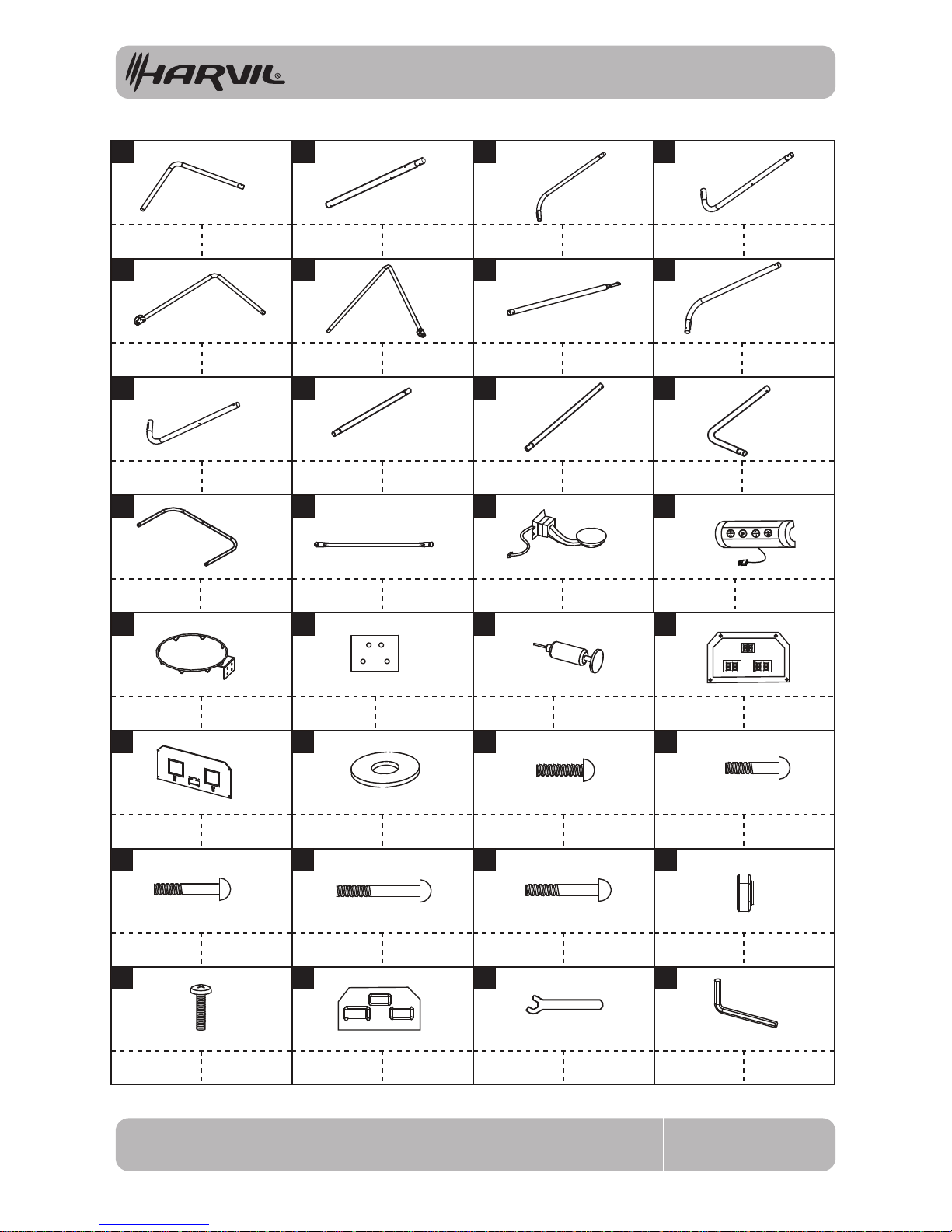
PARTS IDENTIFIER(NOT TO SCALE)
BB125
HOME
VISITOR
TIME
9
10 11
12
13 14 15
16
2 3 4
Tube - 1
Φ32x595x440mm
Tube - 2
Φ32x690mm
Tube - 3
Φ32x860x220mm
Tubo - 3
Φ32x860x220mm
Tube - 4
Φ32x860x220mm
Tubo - 4
Φ32x860x220mm
Tube - 7
Φ32x852mm
Tubo - 7
Φ32x852mm
Tube - 8
Φ32x795x255mm
Φ32x795x255mm Φ32x795x255mm
Tubo - 8
Φ32x795x255mm
Tube - 12
Φ32x550x390mm
Tubo - 12
Φ32x550x390mm
Tube - 9 Tubo - 9
Tubo - 2
Φ32x690mm
Tubo - 1
Φ32x595x440mm
Tube - 5
Φ32x710x550mm
Tubo - 5
Φ32x710x550mm
Tube - 6
Φ32x710x560mm
Tubo - 6
Φ32x710x560mm
Tube - 10
Φ32x700mm
Tubo - 10
Φ32x700mm
Φ32x1040x500mm
Φ32x1040x500mm
Φ13x1035mm
Φ13x1035mm
Tube - 11
Φ32x710mm
Tubo - 11
Tube - 13
Tube - 14 Tubo - 14
Tubo - 13
Φ32x710mm
1
x2 x2 x1 x1
6 7 85
x1 x2 x1
x1 x2 x2 x2
x1 x2
x1
18 19 20
21
22
23
24
25
26
27
28
29
M3.5 x 10mm Bolt
Perno
M3.5 X 10 mm
x4
Electronic Scorer
Face Plate
Placa Frontal
de Marcador
30
x1
Allen Key Llave Allen
x1
31
Wrench
Llave Inglesa
32
x1
17
Paddle Sensor
Sensor de Paleta
Control Box
Caja de Control
Con Cable
Electronic
Scorer
Marcador
Electrónico
x1
x2
x1
Rim Aro
Rim Support
Plate
Placa Metálica de
Soporte de Rampa
x2
Air Pump Bomba de Aire
x1
Backboard
Tablero de
Canasta
x1
M6 Washer Arandela M6
x64
M6 x 20mm Bolt
Perno
M6 x 20mm
x16
M6 x 41mm Bolt
Perno
M6 x 41mm
x6
M6 x 50mm Bolt
Perno
M6x50mm
x4
M6 x 68mm Bolt
Perno
M6x68mm
x4
M6 x 45mm Bolt
Perno
M6 x 45mm
x2
M6 Nut Tuerca M6
x32
x2
3
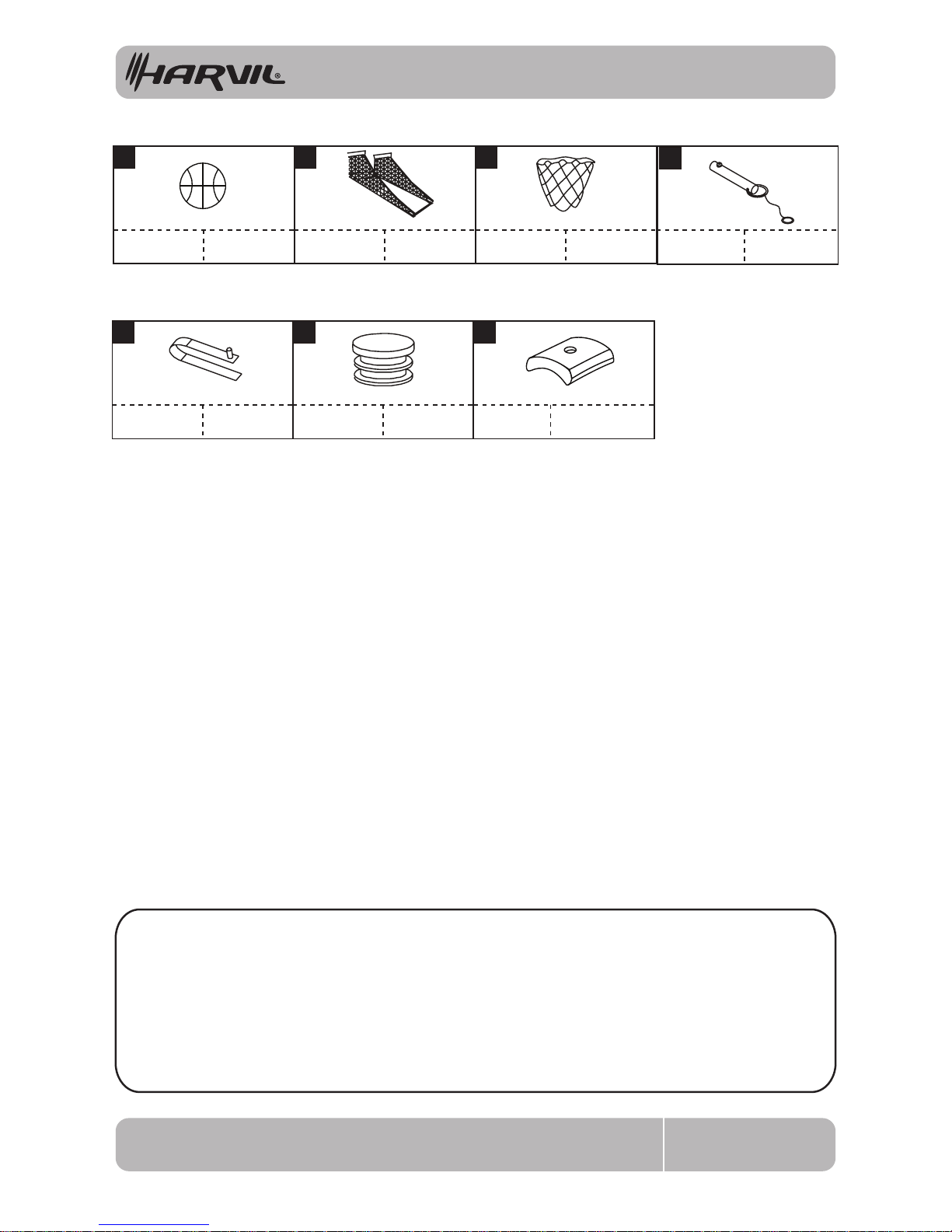
PARTS IDENTIFIER(NOT TO SCALE)
BB125
PINCH HAZARD - USE WITH CAUTION WHEN FOLDING AND UNFOLDING THE GAME.
WARNINGS!
READ AND FOLLOW ALL ASSEMBLY, OPERATION AND SAFETY INSTRUCTIONS CAREFULLY.
CHOKE HAZARD - THIS TABLE CONTAINS SMALL PARTS NOT SUITABLE FOR CHILDREN UNDER 3 YEARS OF AGE.
PRE-INSTALLED PARTS
33
Ball Return Net
Redes de Vuelta
de Pelota
x1
x6
34
Lock Pin
Clavija de
Bloqueo
Spring Lock
Cerradura de
Resorte
Plastic Pole
Insert
Encaje de Poste
Plástico
P1 P2
x13
x2
Nylon Net
Red de Nylon
35
x2
P3
Pole Holder Soporte de Tubo
x6
x2
Basketball
Baloncesto
7" Dia.
36
1. Find a clean, level surface to begin the assembly of your game. This is a very heavy game and assembly
will require at least two strong adults.
2. Remove all of the contents from the box and verify that you have all the parts shown on the Parts
Identier before you begin assembly. Note: Some parts may be pre-installed or pre-assembled.
3. Some gures or drawings may not look exactly like your product. Please read and understand the text
before beginning each assembly step.
4. When installing parts that have more than one screw or bolt, hand tighten all screws and bolts in place
before nishing with a screwdriver or hex wrench.
5. Electric screwdrivers may be helpful during assembly, however, please set a low torque and use extreme
caution because screws may be stripped or over tightened if the electric screwdriver’s torque is set
too high.
ASSEMBLY INSTRUCTIONS
4BB125
5
3
4
8
9
10
P1
P3
6
English
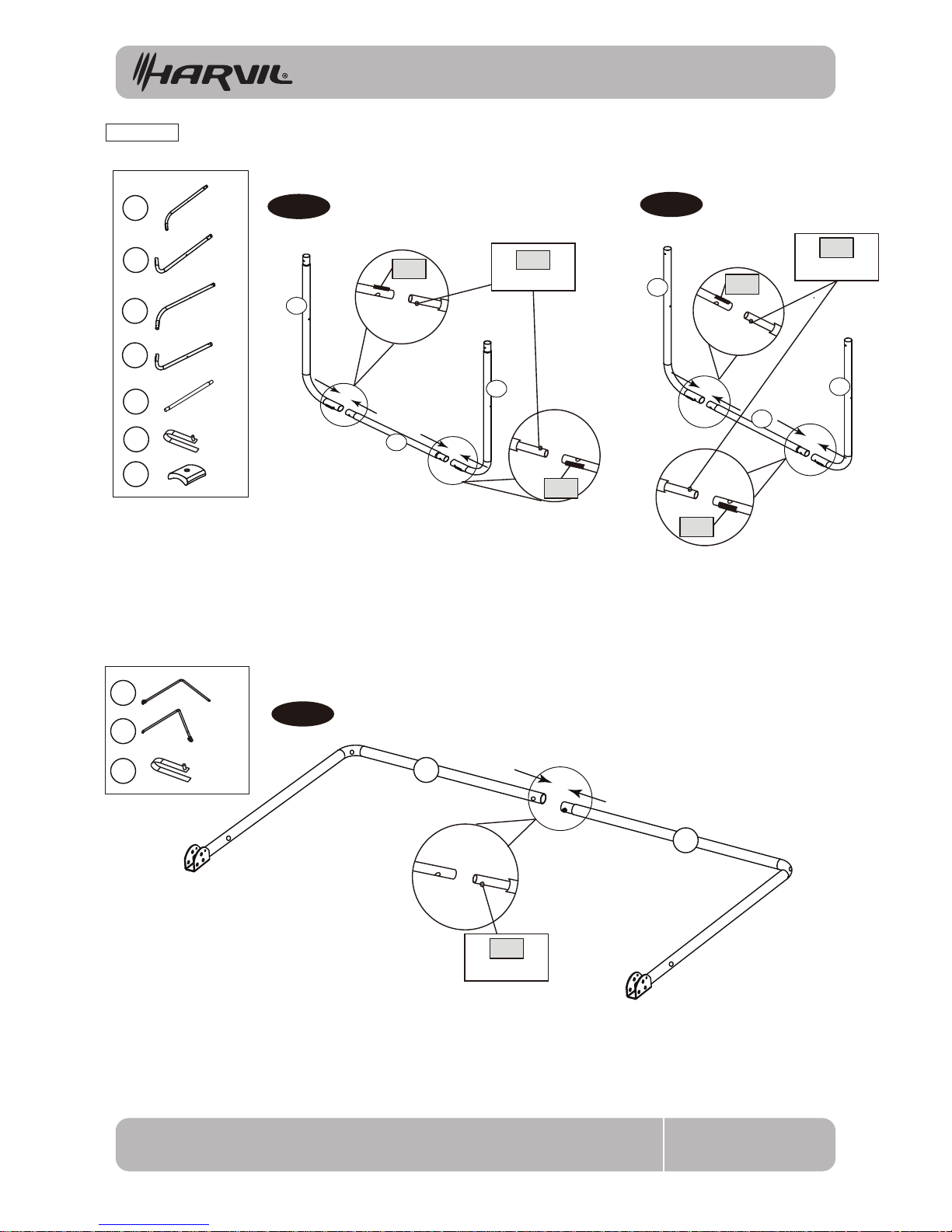
FIG.1 & 2
1. Begin by taking out tubes #10; make sure you have two tubes.
2. Attach tube #10 to tubes #3 and #4 via spring lock as shown in FIG 1.
3. Attach the other tube labeled #10 to tubes #8 and #9 via spring lock as shown in FIG. 2.
FIG.3
4. Next, attach tube #5 and tube #6 together using the spring lock as shown in FIG. 3.
X 1
X 1
FIG. 1
FIG. 2
FIG. 3
Spring Lock
5
6
P1
X 4
X 4
X 1
X 2
X 1
X 1
X 1
P1
X 1
3
4
10
8
9
10
Spring Lock
P1
Spring Lock
P1
P3
P3
P3
P3
ASSEMBLY INSTRUCTIONS
5BB125
22
26
28
English
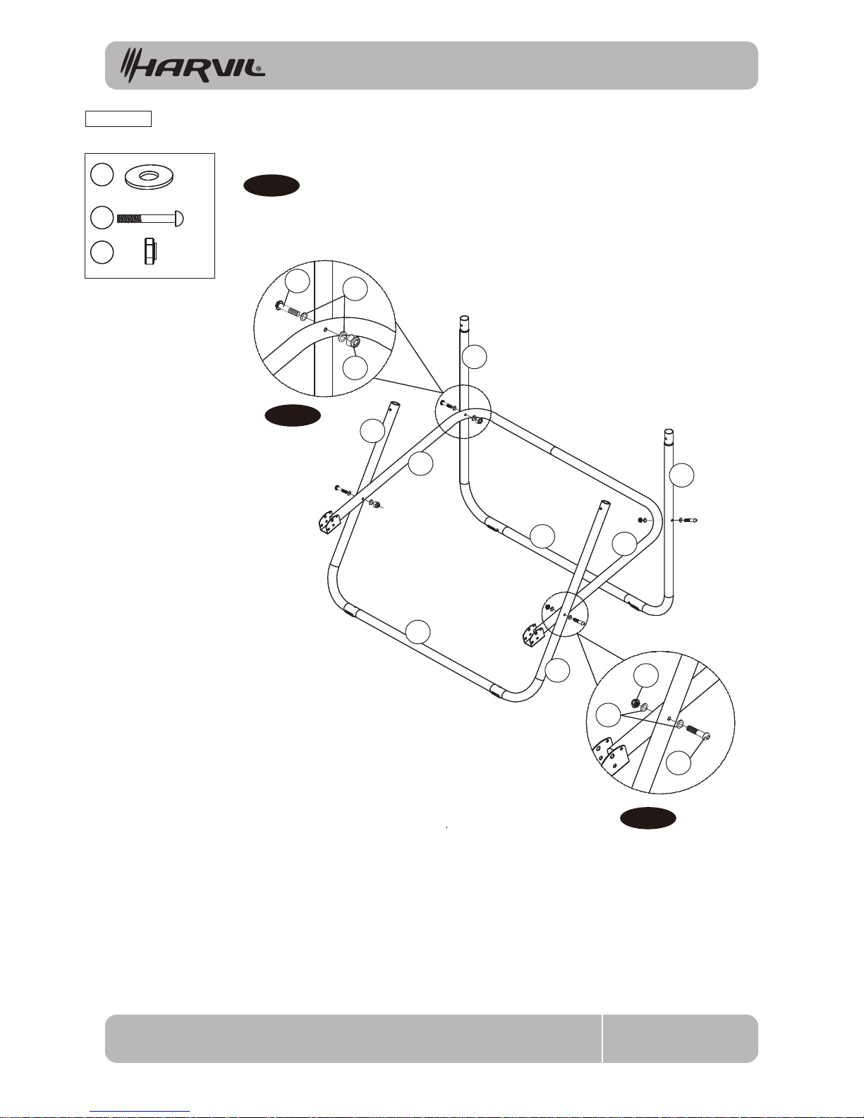
FIG.4
5. Attach joined tubes #5 & #6 to joined tubes #3 & #4 using bolts (#26), washers (#22) and nuts (#28).
6. Then connect joined tubes #8 & #9 to joined tubes #5 & #6, using bolts (#26), washers (#22) and nuts (#28)
as shown in FIG. 4, 4A and 4B.
X 8
X 4
X 4
FIG. 4
FIG. 4B
FIG. 4A
5
3
10
4
9
6
10
8
22
28
26
26
22
28
ASSEMBLY INSTRUCTIONS
6BB125
22
24
28
7
2
2
7
4
10
9
6
10
8
5
3
English
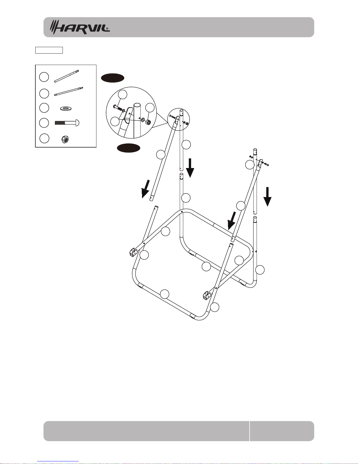
FIG.5
7. Take out the tubes marked #7. Make sure you have two.
8. Attach one tube #7 to tube #8. Attach the other tube #7 to tube #9. Both are fastened via spring lock,
as shown in FIG. 5.
9. Next, take out the tubes marked #2. Make sure you have two.
10. Attach one tube #2 to tube #3. attach the other tube marked #2 to tube #4. Both as fastened via spring lock,
as shown in FIG. 5.
11. Attach both tubes #5 (joined with #8 & #9) to tubes #2 using bolts (#24), washers (#22) and nuts (#28)
as shown in FiG. 5A.
Note: Make sure the spring lock is face down.
T
FIG. 5
FIG. 5A
2
7
22
24
28
X 2
X 2
X 4
X 2
X 2
 Loading...