

Harvia Type KIP45, Type KIP45E, Type KIP60, Type KIP60E, Type KIP80 Instructions For Installation And Use Manual
...
25072003H
KIP45, KIP60, KIP80,
KIP45E, KIP60E, KIP80E, KIP90E
Instructions for installation and use of
Electric Sauna Heater
Gebrauchs- und Montageanleitung des
Elektrosaunaofens
Instructies voor installatie en gebruik van de
elektrische saunaoven
Istruzioni per l’uso e installazione
EN
DE
NL
IT
2
ACHTUNG! Diese Montage- und Gebrauchsanleitung
richtet sich an den Besitzer der Sauna oder an die für die
Pflege der Sauna verantwortliche Person, sowie an den
für die Montage des Saunaofens zuständigen Elektromonteur.
Wenn der Saunaofen montiert ist, wird diese
Montage- und Gebrauchsanleitung an den Besitzer
der Sauna oder die für die Pflege der Sauna
verantwortliche Person übergeben.
Die Garantiezeit für in Familiensaunen verwendete
Saunaöfen und Steuergeräte beträgt zwei (2) Jahre.
Die Garantiezeit für Saunaöfen und Steuergeräte, die in
Gemeinschaftsaunen in Privatgebäuden verwendet
werden, beträgt ein (1) Jahr.
Wir beglückwünschen Sie zu Ihrer guten
Saunaofenwahl!
Befestigung an der Wand
Bei der Befestigung müssen die in Tabelle 1 und in den
Abbildungen angegebenen Anleitungen befolgt
werden. Die Befestigung erfolgt mit Deckschrauben,
die mit dem Saunaofen geliefert werden.
ACHTUNG! Verstärken Sie die Wand hinter dem
Paneel mit einem zusätzlichen Brett, bevor Sie den
Saunaofen an der Wand befestigen.
ACHTUNG! Der Saunaofen muss so montiert
werden, dass die Bedienelemente an der freien Seite
des Saunaofens sichtbar und leicht zu bedienen sind.
• Der Saunaofen kann in einer Wandnische
montiert werden, deren Höhe mindestens
1900 mm beträgt. Siehe Abb. 2.
• Pro Sauna darf nur ein Elektrosaunaofen
montiert werden.
ACHTUNG! Der Schutz von Wänden oder der Decke mit
leichten Abdeckungen, z.B. Asbestplatten, die direkt
an den Wand- oder Deckenflächen befestigt werden,
kann einen gefährlichen Temperaturanstieg in der
Wand und der Decke verursachen.
NOTE! These instructions for installation and use are
intended for the owner or the person in charge of the
sauna, as well as for the electrician in charge of the
electrical installation of the heater.
After completing the installation, the person in
charge of the installation should give these
instructions to the owner of the sauna or to the
person in charge of its operation.
The guarantee period for heaters and control
equipment used in saunas by families is two (2) years.
The guarantee period for heaters and control
equipment used in saunas by building residents is one
(1) year.
Congratulations on your choice!
Mounting on Wall
When fixing, follow the directions in table 1 and the
diagrams. Attachment is by means of the screws
accompanying the heater. Ensure fixing behind heater
is a dequate to support heater – i.e. cross struts in
sauna panelling.
NOTE!: Reinforce the panel behind the heater with an
extra board before mounting the heater on the wall.
NOTE!: There must be enough of working space in
front of the heater control switch.
• The heater can be installed in a recess of a
minimum height 1900 mm (see Fig. 2).
• Only one heater per sauna may be installed.
IMPORTANT: Protecting walls or ceiling with a light
material which is fixed to the surface of the wall or
ceiling may lead to a dangerous rise in temperature in
the wall or ceiling.
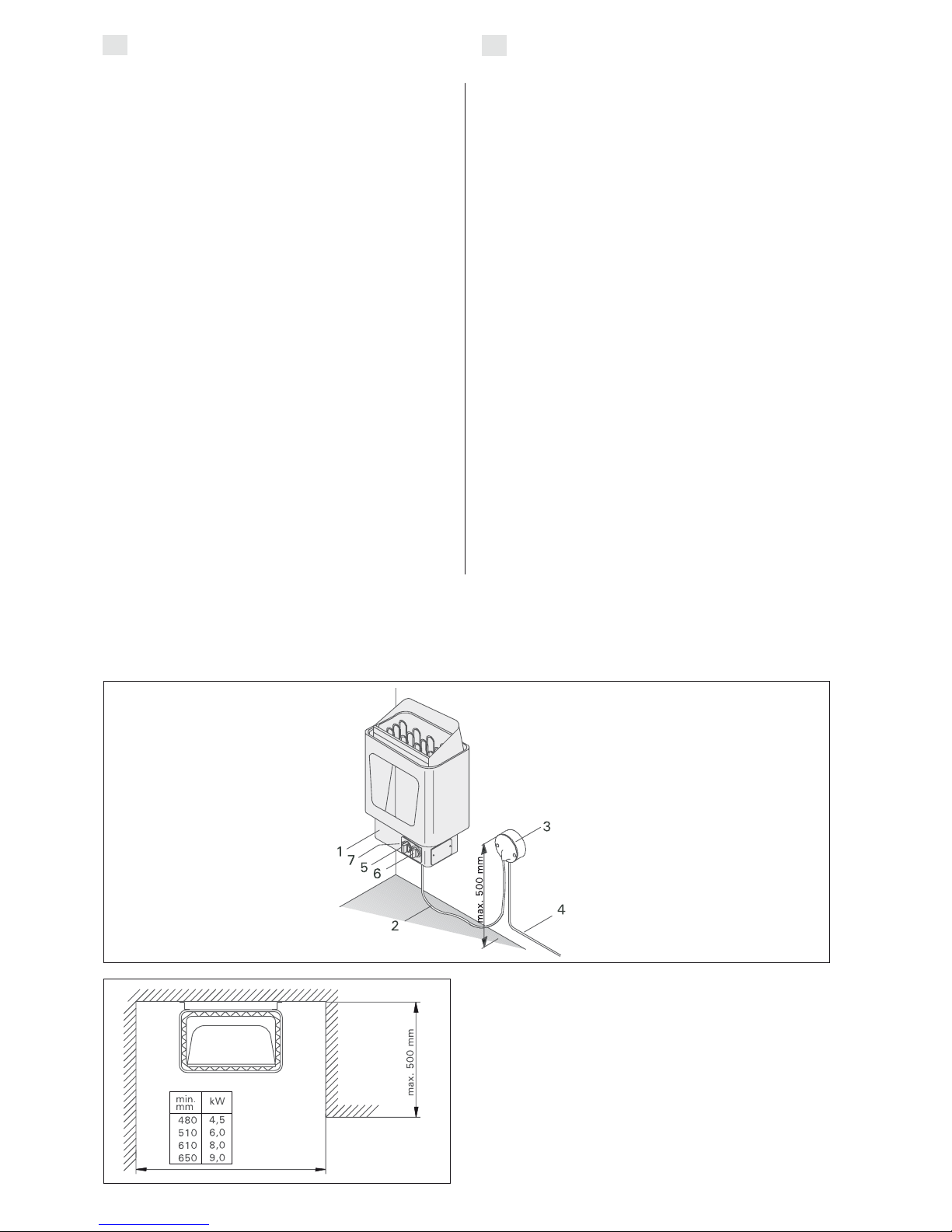
1. Connection box
2. Connection lead
3. Switch box
4. Cable for control centre
(KIP 45E-90E)
4. Installation cable (KIP45-80)
5. Thermostat (KIP 45-80)
6. Timer (KIP 45-80)
7. Reset button for overheating
limiter (KIP 45-80)
1. Anschlußgehäuse
2. Anschlußkabel
3. Klemmdose
4. Kabel zum Steuergerät (KIP 45E-90E)
4. Montage kabel
5. Thermostat (KIP 45-80)
6. Uhrschalter (KIP 45-80)
7. Rücksetzknopf des Überhitzungsschutzes
(KIP 45-80)
Figure 1. Connections and parts of the heater
Abbilgung 1. Anschluß und Teile des Saunaofen
Figure 2.
Installation of the heater in a recess
Abbildung 2.
Montage des Saunaofens in einer
Wandnische
EN
DE
3
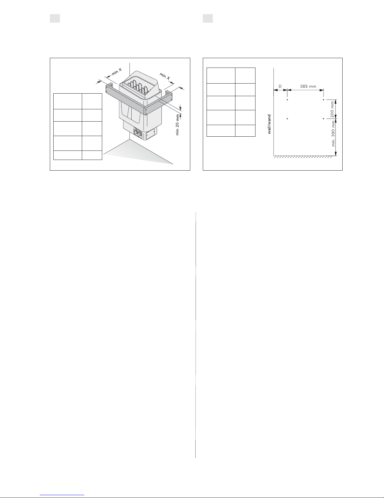
Safety Rail
We recommend if a safety rail is installed around the
heater, follow the directions given in the fig. 3.
Schutzgeländer
Falls um den Saunaofen ein Schutzgeländer gebaut
wird, müssen die in der Abb. 3 angegebenen
Anleitungen befolgt werden.
Figure 3. Safety railing
Abbildung 3. Schutzgeländer des Saunaofens
Figure 4. Location of the mounting rack
of the heater
Abbildung 4. Platz des Montagegestells
des Saunaofens
Controls and use of the heater
The KIP45, KIP60, KIP80 and KIP90 heaters are
equipped with a timer and a thermostat on the lower
part of the heater.
The KIP45E, KIP60E, KIP80E and KIP90E heaters
must be equipped with a separate control unit which
must be installed in a dry area outside of the sauna
room.
Before you switch the heater on check always that
there aren't any things over the heater or in the near
distance of the heater.
Repositioning of Thermostat and Timer
(KIP 45, KIP60, KIP80)
Normally the thermostat and timer are located on the
front of the heater (Fig. 3), but if desired they may
be moved to the right or left side of the heater. Such
repositioning should only be carried out by a qualified
electrician.
1. Turn the heater upside down and detach
the base plate.
2. Remove the timer (1) and thermostat (2)
knobs by pulling outwards.
3. Remove the two holding screws from
the timer and thermostat attachment plate.
4. Remove the cover plate from the side you have
chosen.
5. Replace it with the attachment plate,
complete with the timer and thermostat.
6. Push the knobs into place.
7. Attach the cover plate to the front of the
heater.
8. Check the timer and thermostat connections
and air spaces.
9. Re-attach the heater base plate.
Schaltmechanismus und Anwendung des
Saunaofens
Die Typen KIP45, KIP60, KIP80 und KIP90 sind mit
einer Uhrschalter und einem Thermostat ausgestattet.
Die Typen KIP45E, KIP60E, KIP80E und KIP90E
werden mit einem separaten Steuergerät bedient,
das außerhalb der Saunakabine an einem trockenen
Ort angebracht werden soll.
Bevor Sie den Ofen anschalten, bitte überprüfen,
dass keine Gegenstände auf dem Ofen oder in der
unmittelbarer Nähe des Ofens liegen.
Verlegung des Thermostats und des
Zeitschalters (KIP 45, KIP60, KIP80)
Normalerweise befinden sich der Zeitschalter und
der Thermostat an der Frontseite des Saunaofens
(Abb. 3), aber bei Bedarf können diese auch
entweder an die rechte oder die linke Stirnseite des
Saunaofens verlegt werden. Die Verlegung darf nur
von einem qualifizierten und zugelassenen
Elektroinstallateur erfolgen.
1. Stellen Sie den Saunaofen auf den Kopf und
lösen die Bodenplatte.
2. Lösen Sie die Knöpfe des Zeitschalters (1) und
des Thermostats (2), indem Sie diese herausziehen.
3. Lösen Sie die 2 Befestigungsschrauben der
Halterungsplatte des Zeitschalters und Thermostats.
4. Lösen Sie die Deckplatte der Stirnseite.
5. Montieren Sie die Halterungsplatte an der
gewünschten Seite des Saunaofens und ziehen
die Schrauben fest (der Thermostat und der
Zeitschalter brauchen nicht von der
Halterungsplatte abgenommen zu werden).
6. Schieben Sie die Knöpfe an ihre Plätze.
7. Befestigen Sie die Deckplatte an der Vorderseite
der Anschlussbuchse.
8. Prüfen Sie die Verkabelung des Zeitschalters und des
Thermostats sowie alle Luftzwischenräume.
9. Schließen Sie die Bodenplatte.i.
20
30
30
40
Type/Typ
KIP45/
KIP45E
KIP60/
KIP60E
KIP80/
KIP80E
KIP90E
X min.
mm
48
63
113
133
Type/Typ
KIP45/
KIP45E
KIP60/
KIP60E
KIP80/
KIP80E
KIP90E
D min.
mm
EN DE
4
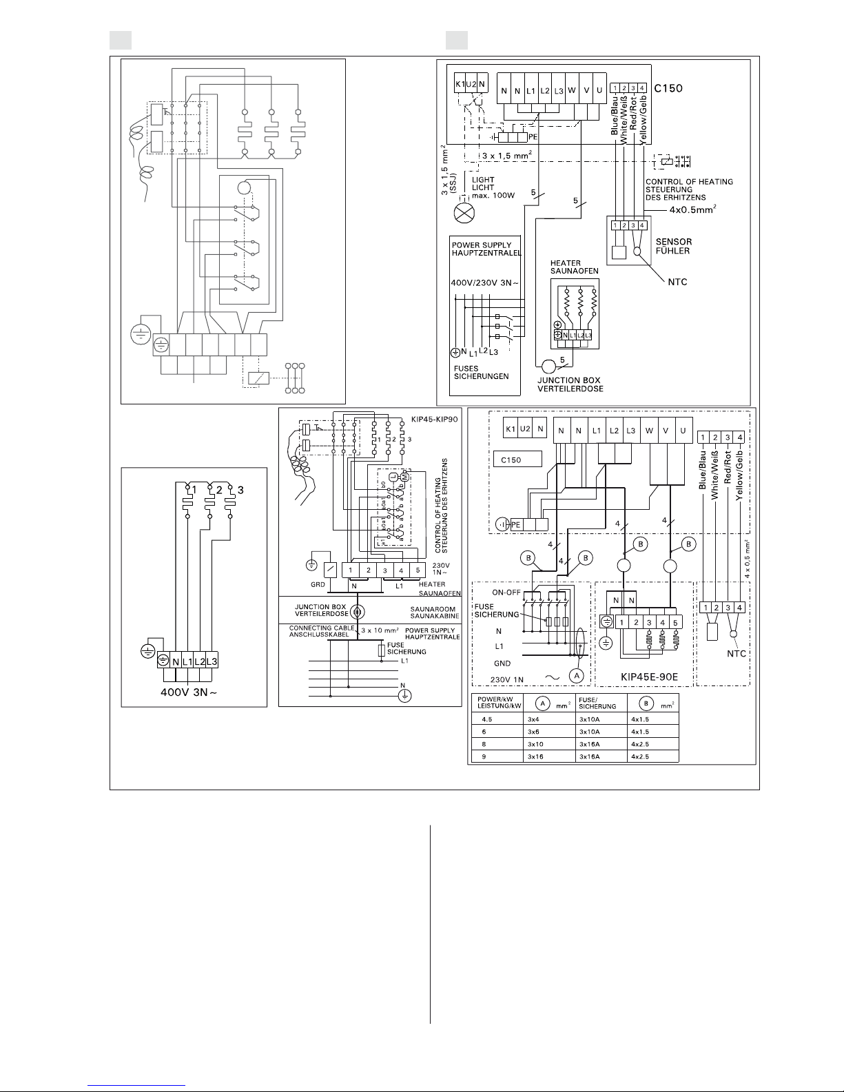
Mains Connection
Due to thermal embrittlement, the use of PVCinsulated wire as the connection cable of the heater is
forbidden.
The heater may only be connected to the electrical
network in accordance with the current regulations
by an authorised, professional electrician. The
heater is semistationarily connected to the junction
box on the sauna wall. The connection cable must be
of rubber cable type H07RN-F or its equivalent. In the
lower part of the heater there is a permanently
installed control unit (KIP45–KIP80). In addition to a
mains connector, the control centre is equipped with
extra connectors which enable the following
additional connections:
a) an indicator light above the steam room (see the
connection diagram). Cross-section of the
connection cable (see Table 1).
b) Locking of electrical heating with the heater (see
connection diagram).
The control cable of the electrical heating is
connected directly to the junction box, and from
there to the terminal strip by a rubber cable with
the thickness of a connection cable.
NOTE! The heater provides a voltage control
(230V) from the P and M connectors.
The KIP-E models require separate control centre C90/
C150 (C150VKK).
Elektroanschlüße
ACHTUNG! PVC-isolierte Kabel dürfen wegen ihrer
schlechten Hitzebeständigkeit nicht als Anschlußkabel des Saunaofens verwendet werden.
Der Anschluß des Saunaofens ans Stromnetz darf
nur von einem zugelassenen Elektromonteur unter
Beachtung der gültigen Vorschriften ausgeführt
werden. Der Saunaofen wird halbfest an die
Klemmdose an der Saunawand befestigt. Als
Anschlußkabel wird ein Gummikabel vom Typ
H07RN-F oder ein entsprechendes Kabel verwendet.
Am Unterteil des Saunaofens ist eine fest eingebaute
Steuerzentrale konstruiert. (KIP45-KIP80).
Außer dem Netzanschluss ist die Steuerzentrale
mit zusätzlichen Anschlüssen ausgestattet, die
folgende Anschlussmöglichkeiten bieten:
a) Kontrolllampe außerhalb der Saunakabine
(s. Schaltplan). Querschnitt des Anschlusskabels
(s. Tabelle 1).
b) Steuerung der Elektroheizung für den Saunaofen
(s. Schaltplan). Das Steuerungskabel für die
Elektroheizung wird direkt zur Klemmdose des
Saunaofens gelegt, und von dort aus direkt mit
einem Gummikabel der gleichen Stärke weiter
zur Klemmleiste des Saunaofens gelegt.
Achtung! Der Saunaofen gibt von einer P- und
M-Klemme eine Spannungssteuerung (230V)
KIP-E Modelle benötigen eine zusätzliche Steuerzentrale
C90/C150 (C150VKK).
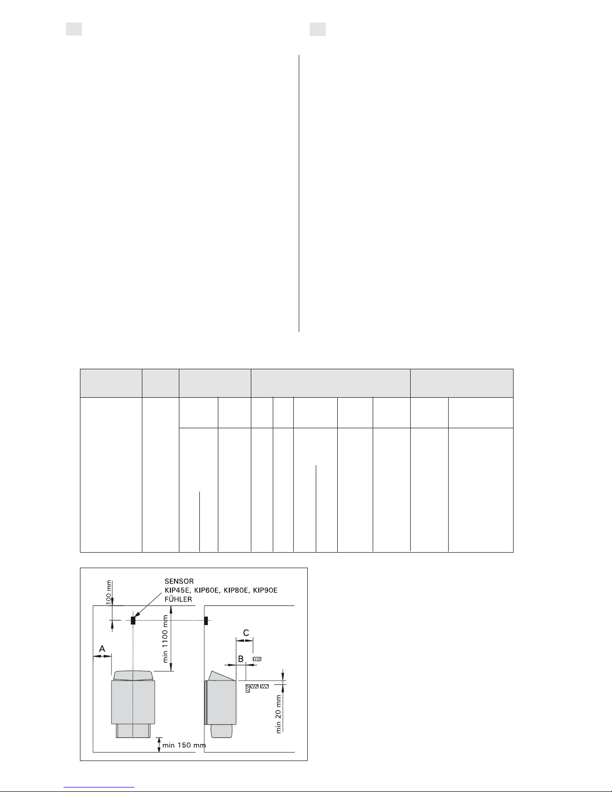
Figure 5. Safety distances from the heater
Abbildung 5. Sicherheitsmindestabstände des
Saunaofens
Table 1.
Tabell 1.
min max min
m3m3mm
KIP45/KIP45E 4,5 3 6 1900 35 20 35 100 1100 150 5 x 1,5 3 x 10
KIP60/KIP60E 6,0 5 8 1900 50 30 50 120 1100 150 5 x 1,5 3 x 10
KIP80/KIP80E 8,0 7 12 1900 100 30 80 150 1100 150 5 x 2,5 3 x 16
KIP90E 9,0 8 14 1900 120 40 100 150 1100 150 5 x 2,5 3 x 16
Heater Output Sauna room Min. distance from heater Connection cable/Fuses
Ofen Leistung Saunakabine Min. Abstand des Ofen Anschlußkabel/Sicherungen
kW
400V3N~
mm
2
*)
**)
A
mm
C
mm
B
mm
KIP-E
Cubic. vol.
Rauminhalt
Height
Höhe
To ceiling
zur Decke
To floor
zum Boden
Fuses
Sicherung
A
*) from front to upper platform
**) from side to wall
*) von der Vorderfläche zur oberen Bank
**) von der Seitenfläche zur Wand
Widht/Breite
41 cm
Depht/Tiefe
28 cm
Height/Höhe
60 cm
Weight/Gewicht
16 kg
Stones/Steine
max.
25 kg
EN
DE
5
Installation of the control unit (C90, C150)
and sensors (KIP45E–KIP90E)
Install the control unit in a dry place outside the sauna
room at the height of about 170 cm. The control unit
includes detailed instructions for fastening the unit on
the wall.
Install the temperature sensor on the wall of the
sauna room above the heater. It should be
installed on the lateral centre line of the heater,
100 mm down-wards from the ceiling. See fig. 5.
Electric heater insulation resistance
When performing the final inspection of the electrical
installations, a ”leakage” may be detected when
measuring the heater’s insulation resistance. The
reason for this is that the insulating material of the
heating resistors has absorbed moisture from the air
Anschluß des Steuergerätes (C90, C150)
und der Fühler (KIP45E–KIP90E)
Das Steuergerät wird in einem trockenen Raum
außerhalb der Saunakabine in etwa 170 cm Höhe
angebracht. In Verbindung mit dem Steuergerät
werden genauere Anweisungen zu dessen Befestigung an der Wand gegeben.
Der Temperaturfühler wird an der Saunawand oberhalb des
Saunaofens, 100 mm unterhalb der Decke auf der Achse in
Breitenrichtung des Saunaofens angefracht. Siehe Abb. 5.
Isolationswiderstand des Elektrosaunaofens
Bei der Endkontrolle der Elektroinstallationen kann bei
der Messung des Isolationswiderstandes ein “Leck”
auftreten, was darauf zurückzuführen ist, daß
Feuchtigkeit aus der Luft in das Isolationsmaterial der
Heizwiderstände eingetreten ist (bei Lagerung und
Figure 6. Electrical connections of heater
Abbildung 6. Elektroanschlüsse des Saunaofens
EN DE
400V 3N~
123
M
N
L1 L2
L3 N P
a1
a1
a1
b0
b
b0
b0
b
b
a
a
a
CONTROL OF HEATING
STEUERUNG DES ERHITZENS
KIP 45-90
KIP45E-KIP90E
6
(storage transport). After operating the heater for a few
times, the moisture will be removed from the resistors.
Do not connect the power feed for the heater through
the RCD (residual current device)!
Piling of the Sauna Stones
The sauna stones for an electric heater should be 4–8 cm in
diameter. The heater stones should be solid blocks of
stone specially intended for use in the heater. Neither
light, porous ceramic “stones“ of the same size nor
soft potstones should be used in the heater, because
they may cause the resistance temperature to rise too
high as a result of which the resistance may be broken.
Stone dust should be washed off before piling the
stones. The stones should be piled into the stone
compartment over the grating, between the heating
elements (resistances) so that the stones support
each other. The weight of the stones should not lie
on the heating elements.
The stones should not be piled too tightly, so that
air can flow through the heater. The stones should
be fitted loosely, and not wedged between the
heating elements. Very small stones should not be
put into the heater at all.
The stones should completely cover the heating
elements. However, they should not form a high pile
on the elements.
The stones disintegrate with use. Therefore, they
should be rearranged at least once a year or even
more often if the sauna is in frequent use. At the
same time, any pieces of stones should be removed
from the bottom of the heater, and disintegrated
stones should be replaced with new ones.
The guarantee does not cover any faults caused by
the use of stones not recommended by the plant.
Neither does the guarantee cover any faults caused
by disintegrated or too small stones blocking the
heater ventilation.
No such objects or devices should be placed inside
the heater stone space or near the heater that could
change the amount or direction of the air flowing
through the heater, thus causing the resistance
temperature to rise too high, which may set the wall
surfaces on fire!
Sauna Water
The water to be thrown on the heated stones should meet
the requirements of clean household water. The factors
essentially affecting the quality of water include the
following:
• humuos content (colour, taste, precipitates);
recommended content less than 12 mg/litre.
• iron content (colour, smell, taste, precipitates);
recommended content less than 0,2 mg/litre.
• hardness - the most important substances are
manganese (Mn) and calcium (Ca);
recommended content of manganese 0,05 mg/
litre, calcium less than 100 mg/litre.
Calcareous water leaves a white, sticky layer on
the stones and metal surfaces of the heater.
Calcification of the stones deteriorates the heating
properties.
Ferrous water leaves a rusty layer on the surface
of the heater and elements, and causes corrosion.
The use of humous, chlorinated water and seawater
Transport). Die Feuchtigkeit entweicht aus den
Widerständen nach zwei Erwärmungen.
Schalten Sie den Netzstrom des Elektrosaunaofens
nicht über den Fehlerstromschalter ein!
Aufschichten der Saunaofensteine
Die passenden Steine für einen Elektrosaunaofen
haben einen Durchmesser von 4–8 cm. Als Saunaofensteine sollten speziell für Saunaöfen gedachte,
bekannte, massive Bruchsteine verwendet werden.
Die Verwendung leichter, poröser und gleichgroßer
keramischer Steine ist verboten, da durch sie die
Widerstände überhitzt und beschädigt werden
können. Als Saunaofensteine dürfen auch keine
weichen Topfsteine verwendet werden.
Die Steine sollten vor dem Aufschichten von
Steinstaub befreit werden. Die Steine werden auf
den Rost in den Saunaofen in die Zwischenräume der
Heizelemente so gesetzt, daß die Steine einander
tragen. Das Gewicht der Steine darf nicht von den
Heizelementen getragen werden.
Die Steine dürfen nicht zu dicht gesetzt werden, damit
die Luftzirkulation nicht behindert wird. Auch dürfen die
Steine nicht eng zwischen den Heizelementen verkeilt werden, die Steine sollten locker gesetzt werden. Sehr kleine
Steine sollen nicht in den Saunaofen gelegt werden.
Die Steine sollen die Heizelemente vollständig
bedecken, sie dürfen aber nicht hoch über den Saunaofen herausragen.
Während des Gebrauchs werden die Steine spröde.
Aus diesem Grund sollten die Steine mindestens einmal
jährlich neu aufgeschichtet werden, bei starkem
Gebrauch öfter. Bei dieser Gelegenheit entfernen Sie
bitte auch Staub und Gesteinssplitter aus dem unteren
Teil des Saunaofens und erneuern beschädigte Steine.
Die Garantie kommt nicht für Schäden auf, die durch
Verwendung anderer als vom Werk empfohlener Saunaofensteine entstehen. Die Garantie kommt auch nicht
für Schäden des Saunaofens auf, die durch Verstopfung
der Luftzirkulation durch bei Gebrauch spröde
gewordene Steine oder zu kleine Steine entstehen.
In der Steinkammer oder in der Nähe des Saunaofens dürfen sich keine Gegenstände oder Geräte
befinden, die die Menge oder die Richtung des durch
den Saunaofen führenden Luftstroms ändern, und
somit eine Überhitzung der Widerstände sowie
Brandgefahr der Wandflächen verursachen!
Aufgußwasser
Als Aufgußwasser sollte nur Wasser verwendet
werden, das die Qualitätsvorschriften für Haushaltswasser erfüllt. Wichtige Faktoren für die Wasser-
qualität sind:
• Humusgehalt(Farbe, Geschmack, Ablagerungen);
Empfehlung unter 12 mg/l.
• Eisengehalt (Farbe, Geruch, Geschmack,
Ablagerungen); Empfehlung unter 0,2 mg/l.
• Härtegrad; die wichtigsten Stoffe sind Mangan
(Mn) und Kalzium (Ca) oder Kalk; Empfehlung
für Mangan unter 0,05 mg/l und für Kalzium
unter 100 mg/l.
Bei Verwendung kalkhaltigen Wassers verbleibt auf
den Steinen und Metalloberflächen des Saunaofens
eine helle, cremeartige Schicht. Die Verkalkung der
Steine schwächt die Aufgußeigenschaften ab.
Bei Verwendung eisenhaltigen Wassers verbleibt
auf der Ofenoberfläche und den Widerständen eine
rostige Schicht, die Korrosion verursacht.
EN
DE
 Loading...