

Harvia Sentiotec ALASKA MINI Instructions For Installation And Use Manual
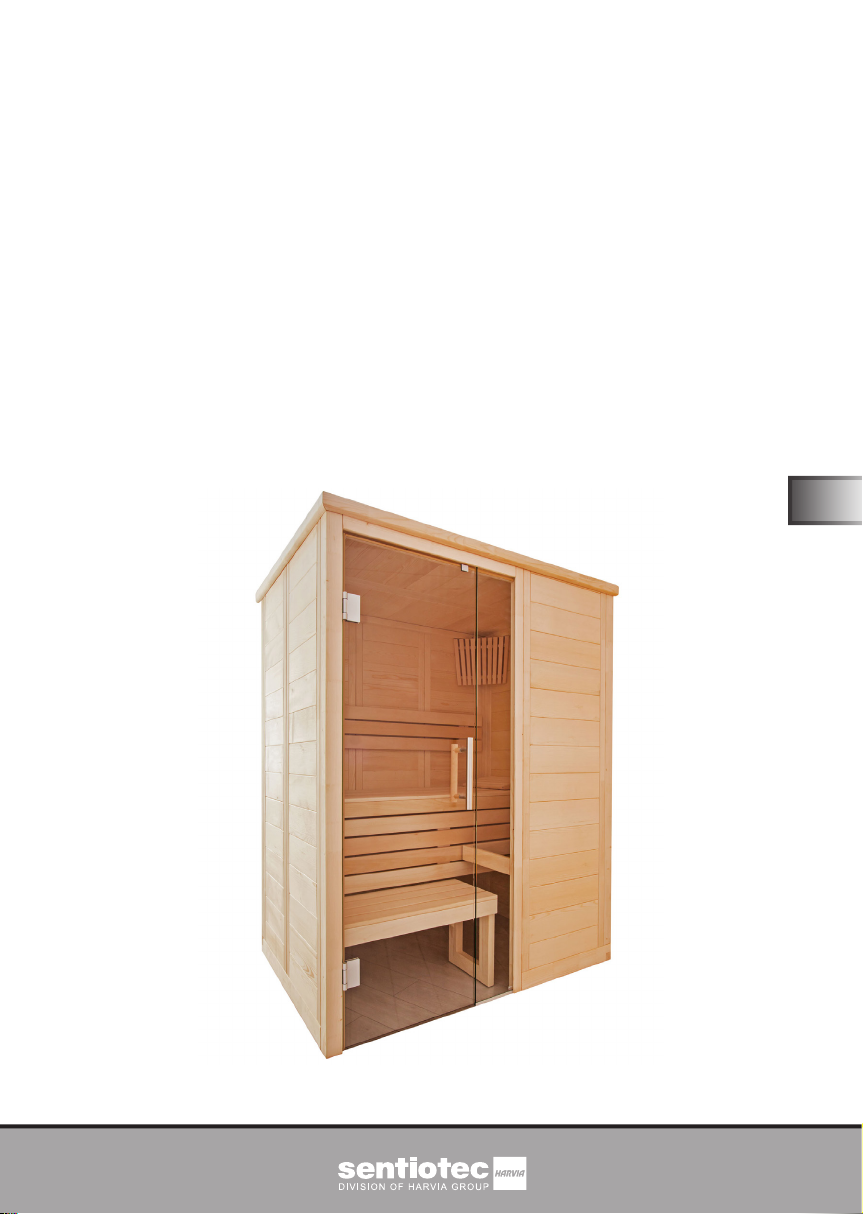
Solid wood sauna
ALASKA
MINI
160 x 110 x 204 cm
INSTRUCTIONS FOR INSTALLATION AND USE
English
EN
ALASKA-MN
Version 07/18 Ident. no. 1-030-270

Table of Contents
1. Preparing for installation 3
1.1. Tools required 4
1.2. Maintenance and cleaning 5
1.3. Disposal 5
1.4. ALASKA MINI parts list 6
2. Cabin installation 8
2.1. Base frame installation 8
2.2. Wall element installation 9
2.3. Ceiling installation 16
2.4. Ventilation slit installation 18
2.5. Installing interior ttings 18
2.6. Installing accessories 24
2.7. Installing glass door 26
2.8. Installing roof trim 28
2.9. Installing ceiling cover slat 29
3. Floor plan 30
3.1. Right oor plan 30
3.2. Left oor plan 31
3.3. Changes to the left oor plan installation 32

Instructions for installation and use p. 3/34
1. Preparing for installation
Read these installation instructions carefully and keep them within reach when
using the sauna, so that you can look up product information at any time.
These installation instructions can also be found in the downloads section
of our website: www.sentiotec.com/downloads.
Important note:
● Before you begin work, check the parts list to ensure that all the individual
parts have been delivered. If you discover any missing parts, notify your
dealer within 14 days of receiving the sauna cabin.
● The room that the sauna is installed in must be dry and ensure an appropriate
amount of air circulation.
● The oor must be level and even, preferably a stone or tiled oor.
● A minimum room height of 230 cm is required for the cabin installation work.
● A distance of at least 5 cm from the wall must be maintained.
● The inside of the wooden parts used must not be treated with any impreg-
nating material.
● You need an assistant for the installation.
● Wood is a natural product that can swell, shrink or warp, despite good stor-
age. For this reason, some force may be necessary during the installation.
● All screw ttings must be pre-drilled.
EN
Attention!
The electrical connection may only be performed by a qualied electrician
or similarly trained person.

Instructions for installation and use p. 4/34
1.1. Tools required
● Hammer with a wooden head or a mallet
● Cordless screwdriver with bits for cross-head screws and Torx
● Roller tape measure
● Drill bits with a diameter of 3 mm, 10 mm, 20 - 30 mm
(for sauna heater power cable)
● Spirit level
● 1.5 mm hexagonal socket wrench
● Utility knife
● Ladder
● Backsaw
This symbol indicates tips and useful information
Pre-drill
Cut to real measurement with backsaw
Check the right angle:
80 cm
60 cm
100 cm

Instructions for installation and use p. 5/34
1.2. Maintenance and cleaning
● The sauna should be cleaned with a damp cloth. Only use warm water – no
cleaning products.
● We recommend heating the cabin once a month if the sauna is not used for
a long time.
Pitch pockets are not grounds for return, since they can always appear in
spruce wood and the depth at which they lie cannot be detected during
the sorting-out process.
If these are just under the surface, heat can cause them to soften and
“bleed”.
The leaking pitch can be removed with a rag soaked in acetone. If only
droplets of pitch occur, allow these to harden and then carefully scrape
them off with a knife.
1.3. Disposal
● Please dispose of packaging materials in accordance with the appli-
cable disposal regulations.
● Used units contain reusable materials as well as hazardous substanc-
es. Therefore, do not dispose of your used unit with household waste,
but rather do so in accordance with the locally applicable regulations.
EN

Instructions for installation and use p. 6/34
1.4. ALASKA MINI parts list
No. of items Name Dimensions
Base frame
1 Base frame 156 x 9 x 4 cm
1 Base frame 108 x 9 x 4 cm
1 Base frame 102 x 9 x 4 cm
1 Base frame 64 x 9 x 4 cm
Wall elements
1 A/B ventilation element with Multiclip 193 x 48 x 4 cm
1 A/B wall element 193 x 48 x 4 cm
1 A/B wall element with Multiclip 193 x 48 x 4 cm
4 A/A wall elements with Multiclip 193 x 48 x 4 cm
1 A/A electrical element with Multiclip 193 x 58 x 4 cm
1 Element above door, oor plan (right) 81.5 x 10.1 x 4 cm
1 Element above door, oor plan (left) 81.5 x 10.1 x 4 cm
Ceiling elements
2 Ceiling elements 146 x 49 x 4 cm
Corner posts
3 90° corner posts with Multiclip 193 x 6 x 6 cm
1
Corner post with front hinge for glass door with Multiclip
1 Post for glass element, 8 mm groove 202 x 4.5 x 4 cm
Support slats
2 Roof support slats 140 x 4 x 4 cm
2 Roof support slats 100 x 4 x 4 cm
2 Roof cover slats 144 x 1.2 x 4 cm
2 Roof cover slats 104 x 1.2 x 4 cm
2 Bench support slats 58 x 4 x 4 cm
2 Mounting slats for bench screen 26 x 4 x 4 cm
202 x 6 x 7.5 cm

Instructions for installation and use p. 7/34
No. of items Name Dimensions
Interior ttings
1 Bench 147 x 62 x 9 cm
1 Foot step panel 80 x 35 x 9 cm
2 Foot step feet 43 x 33 x 4 cm
2 Foot step struts, 2 x 45° diagonal 49.5 x 8 x 2 cm
1 Backrests 138 x 26 x 4 cm
1 Bench screen 147 x 35 x 4 cm
1 Heater protection grille – lime wood 62.5 x 8 x 2 cm
1 Heater protection grille – lime wood 37.5 x 8 x 2 cm
3
Mounting slats for heater protection grille – spruce
1 Headrest 43 x 25 x 7 cm
1 Lamp protection grille 38 x 32 x 4 cm
1 Ventilation slit 52 x 14 x 1.5 cm
Glass elements
1 Glass door
1 Glass element
Roof rim slats
1 Roof rim slat 160 x 6 x 4 cm
2 Roof rim slats 115 x 6 x 4 cm
Accessories
1 U aluminium prole
1 Door handle set wood/stainless steel
1 2 door hinges 8653-02
1 Door magnet, sleeve plate
1 Sauna lamp
1 Template for Multiclip installation
1 3 Silicon cables: 5 x 2.5 mm²
1 3 Silicon cables: 3 x 1.5 mm²
1 Installation material set
1 Installation instructions
7 x 2.5 x 2.5 cm
191.5 x 59 x 0.8 cm
194.5 x 22.4 x 0.8
cm
21.1 x 1.2 x 1.5 cm
EN
Instructions for installation and use p. 8/34
2. Cabin installation
The cabin can have a right or left set up, please note the corresponding oor
plans on Page 30 and Page 31.
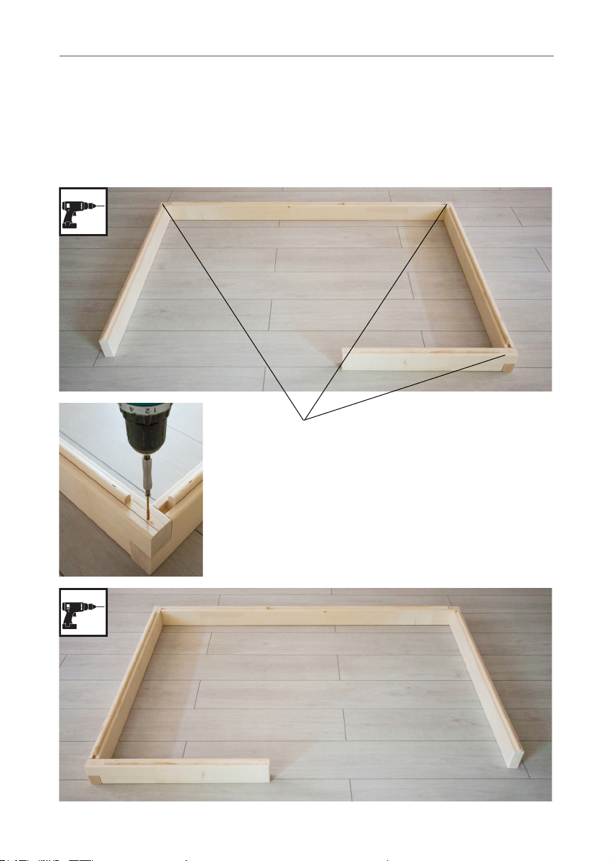
2.1. Base frame installation
156 cm
108 cm
102 cm
Right oor plan
64 cm
3 mm drill bit, 3 screws 4 x 70 mm
156 cm
102 cm
108 cm
64 cm
Left oor plan
Instructions for installation and use p. 9/34
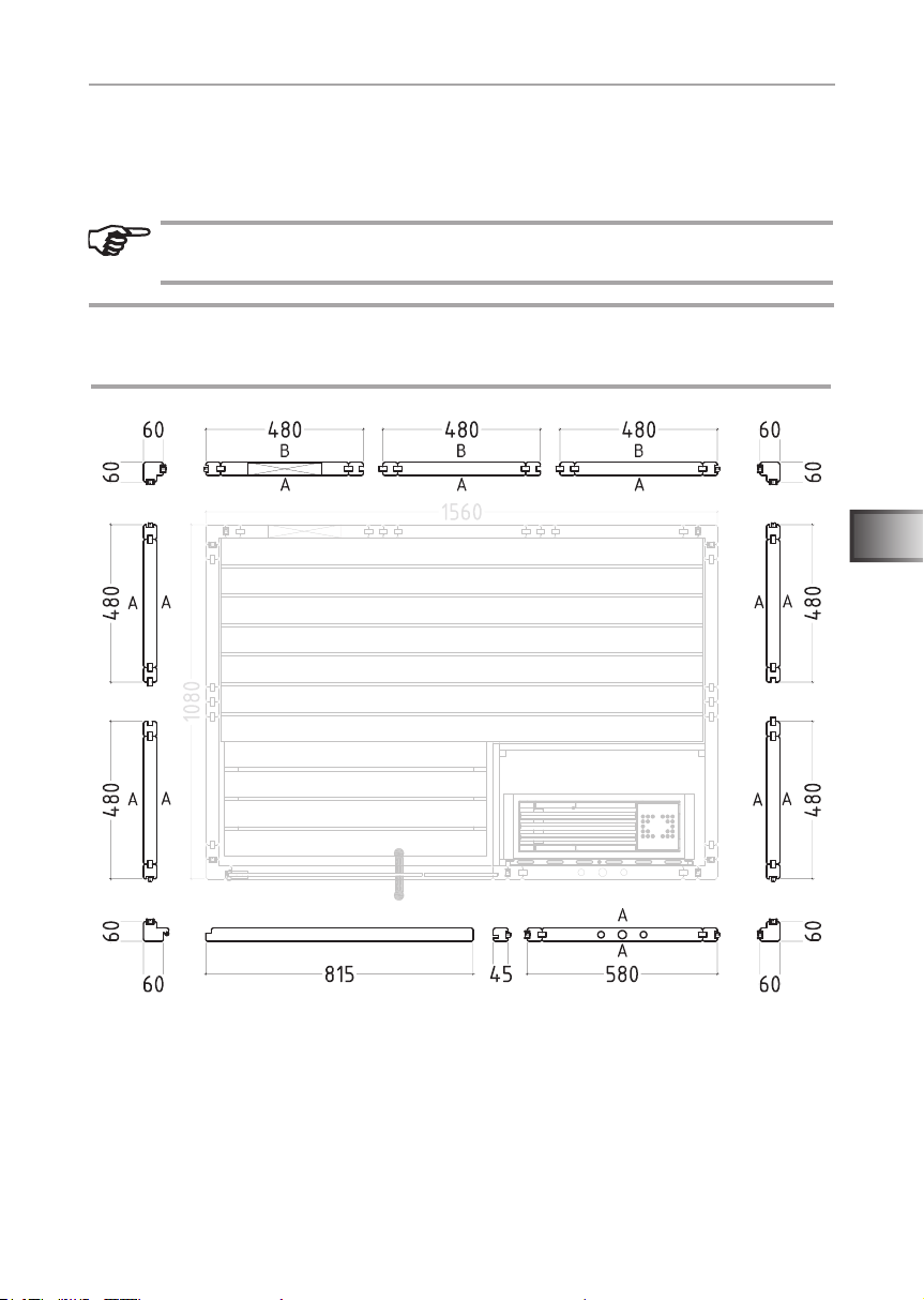
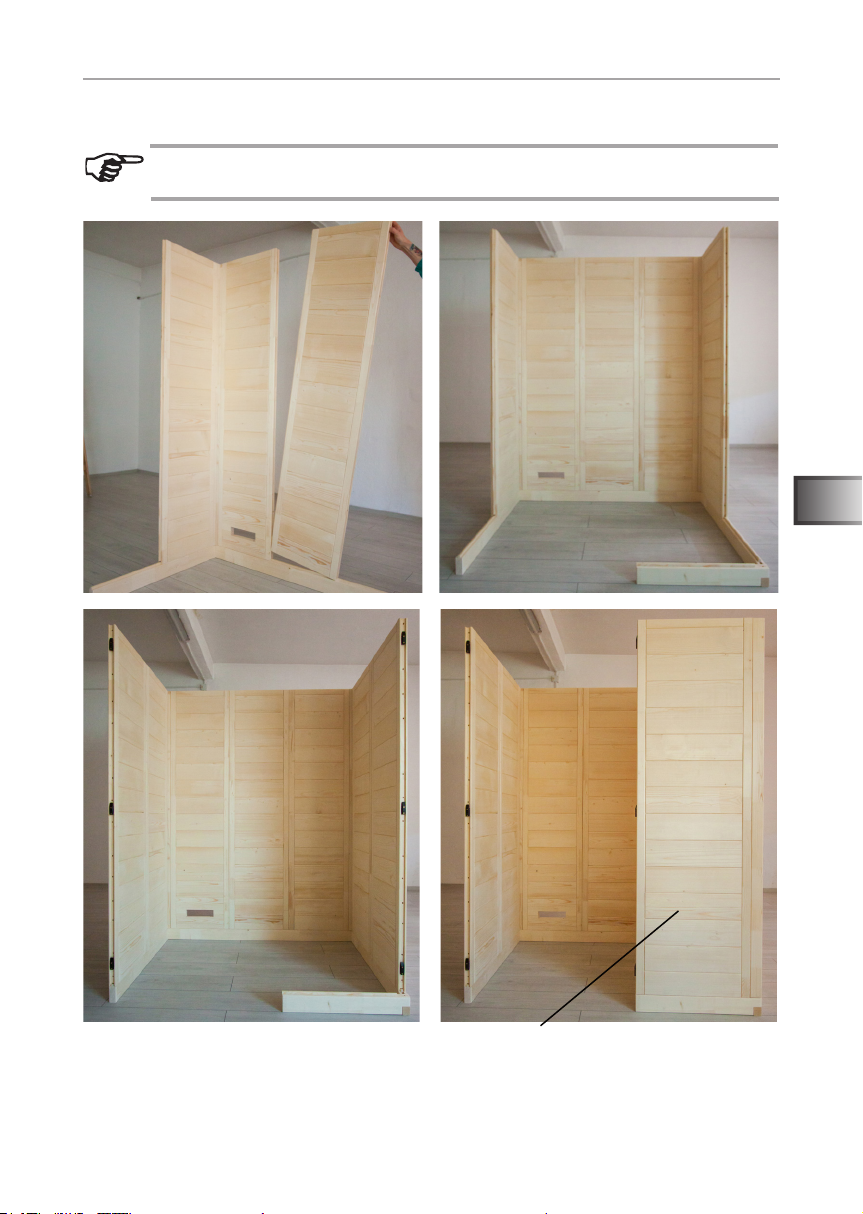
2.2. Wall element installation
The corner posts are connected to the wall elements using Multiclips. The other
wall elements are connected by tongue and groove and are screwed together.
A always refers to the visible side. This is labelled on the top side of
the wall elements.
Attention!
The installation subsequently described is for the right oor plan.
For changes affecting installation for the left oor plan see Page 32.
* *
*
*
* Multiclips
Right oor plan
*
*
EN
*
*
Instructions for installation and use p. 10/34
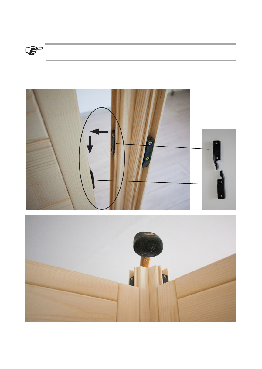
Installing corner posts with wall elements
Pre-assemble the wall elements with the corner posts on the oor and
then place these posts on the base frame.
Insert the corner post on the wall elements, moving it downwards. When doing
this, ensure that the Multiclips are correctly aligned (see below). The corner post
must be ush with the wall elements.
Multiclip
Instructions for installation and use p. 11/34
Installing wall elements
The electrical element has drill holes for laying cables. For the position,
see oor plans on Page 30 and Page 31.
EN
Electrical element
 Loading...