

HARVEY Chemiclave EC5500, Chemiclave EC6000 Service Manual

BARNSTEAD THERMOLYNE CORPORATION
®
Harvey
Chemiclave
EC Series Sterilizers
SERVICE MANUAL
LT1121X2 • 11/13/00
1

Table of Contents
Introduction ................................................................................................................................................................. 4
General Specifications ................................................................................................................................................ 5
General Description .................................................................................................................................................... 6
Controls and Features............................................................................................................................................... 6
Power Switch .......................................................................................................................................................... 6
Control Panel .......................................................................................................................................................... 6
Chemi-Filter............................................................................................................................................................. 8
Door ........................................................................................................................................................................ 8
Drain........................................................................................................................................................................ 8
Pressure Relief Valve.............................................................................................................................................. 8
Piping Components ................................................................................................................................................... 8
Reservoir ................................................................................................................................................................. 8
Metering Valve ........................................................................................................................................................ 8
Chamber ................................................................................................................................................................. 9
Pressure Gauge ...................................................................................................................................................... 9
Pressure Relief Valve.............................................................................................................................................. 9
Condenser............................................................................................................................................................... 9
Condensate Tank .................................................................................................................................................... 9
Drain........................................................................................................................................................................ 9
Exhaust ................................................................................................................................................................. 10
Chemi-Filter........................................................................................................................................................... 10
Electrical Components ............................................................................................................................................ 10
Printed Circuit Boards ........................................................................................................................................... 10
Power Cord ........................................................................................................................................................... 11
Power Switch ........................................................................................................................................................ 11
Control Panel ........................................................................................................................................................ 11
Heater ................................................................................................................................................................... 11
Thermostat ............................................................................................................................................................ 11
Overtemp Switch ................................................................................................................................................... 12
Valve Shaft Switch ................................................................................................................................................ 12
Pressure Switch .................................................................................................................................................... 12
Sterilant Level Switch ............................................................................................................................................ 12
Principles of Operation .............................................................................................................................................. 13
Chemiclave Cycle (EC5500 & 6000)....................................................................................................................... 13
Filling the Reservoir .............................................................................................................................................. 13
Power ON.............................................................................................................................................................. 13
Warm Up ............................................................................................................................................................... 13
Ready/Load ........................................................................................................................................................... 13
Pressurization ....................................................................................................................................................... 13
Exposure ............................................................................................................................................................... 14
Depressurization ................................................................................................................................................... 14
Purge..................................................................................................................................................................... 14
Complete ............................................................................................................................................................... 14
Wiring Diagrams........................................................................................................................................................ 24
Troubleshooting ........................................................................................................................................................ 26
Maintenance and Servicing ....................................................................................................................................... 28
Piping Components ................................................................................................................................................. 28
Leaks..................................................................................................................................................................... 28
Metering Valve ...................................................................................................................................................... 30
2

TABLE OF CONTENTS
Pressure Gauge .................................................................................................................................................... 33
Pressure Relief Valve............................................................................................................................................ 33
Condenser............................................................................................................................................................. 34
Condensate Tank .................................................................................................................................................. 34
Door ...................................................................................................................................................................... 34
Purge Pump .......................................................................................................................................................... 35
Air Filter ................................................................................................................................................................. 36
Check Valve .......................................................................................................................................................... 36
Electrical Components ............................................................................................................................................ 36
Fuses .................................................................................................................................................................... 36
Printed Circuit Boards (PCBs)............................................................................................................................... 37
Timer ..................................................................................................................................................................... 41
Power Switch ........................................................................................................................................................ 41
Heater ................................................................................................................................................................... 42
Chamber Temperature .......................................................................................................................................... 43
Thermostat ............................................................................................................................................................ 43
Overtemp Switch ................................................................................................................................................... 44
Pressure Switch .................................................................................................................................................... 45
Sterilant Level Switch ............................................................................................................................................ 45
Check Valve .......................................................................................................................................................... 46
Electrical Components ............................................................................................................................................ 46
Recommended Spare Parts .................................................................................................................................... 47
General Maintenance ................................................................................................................................................ 48
Daily ........................................................................................................................................................................ 48
Cleaning the Door Gasket ..................................................................................................................................... 48
Draining the Waste Tank....................................................................................................................................... 49
Weekly .................................................................................................................................................................... 50
Cleaning the Chamber and Trays ......................................................................................................................... 50
Monthly.................................................................................................................................................................... 50
Checking the Pressure Relief Valve...................................................................................................................... 50
When Required ....................................................................................................................................................... 51
Replacing the Chemi-Filter.................................................................................................................................... 51
Finding the Replacement Date ............................................................................................................................. 51
Replacing the Door Gasket ................................................................................................................................... 52
Door Adjustment ................................................................................................................................................... 53
Recommended Spare Parts .................................................................................................................................... 54
Two Year Limited Warranty....................................................................................................................................... 55
3
Introduction
Note
To save space, most figures in this
manual show only one of the models.
This is usually the EC5500. Both
models contain similar or identical
components and operate in a similar
way.
The Harvey® Chemiclave sterilizer is a safe, fast and
effective sterilizer for use in medical and dental offices,
hospitals, clinics and other health care facilities.
To sterilize goods, Chemiclave sterilizers use an unsaturated chemical vapor process. The active ingredient in
Vapo-Steril, the liquid sterilant, is formaldehyde.
Two models of the EC Series are available: the EC5500 (8”
chamber diameter) and the EC6000 (10” chamber diameter).
The model with a larger chamber (EC6000) can process a
larger load. Features of each model are summarized in
Figures 1 and 12 and in “General Specifications.”
Figure 1: EC Series Chemiclave Sterilizers
4
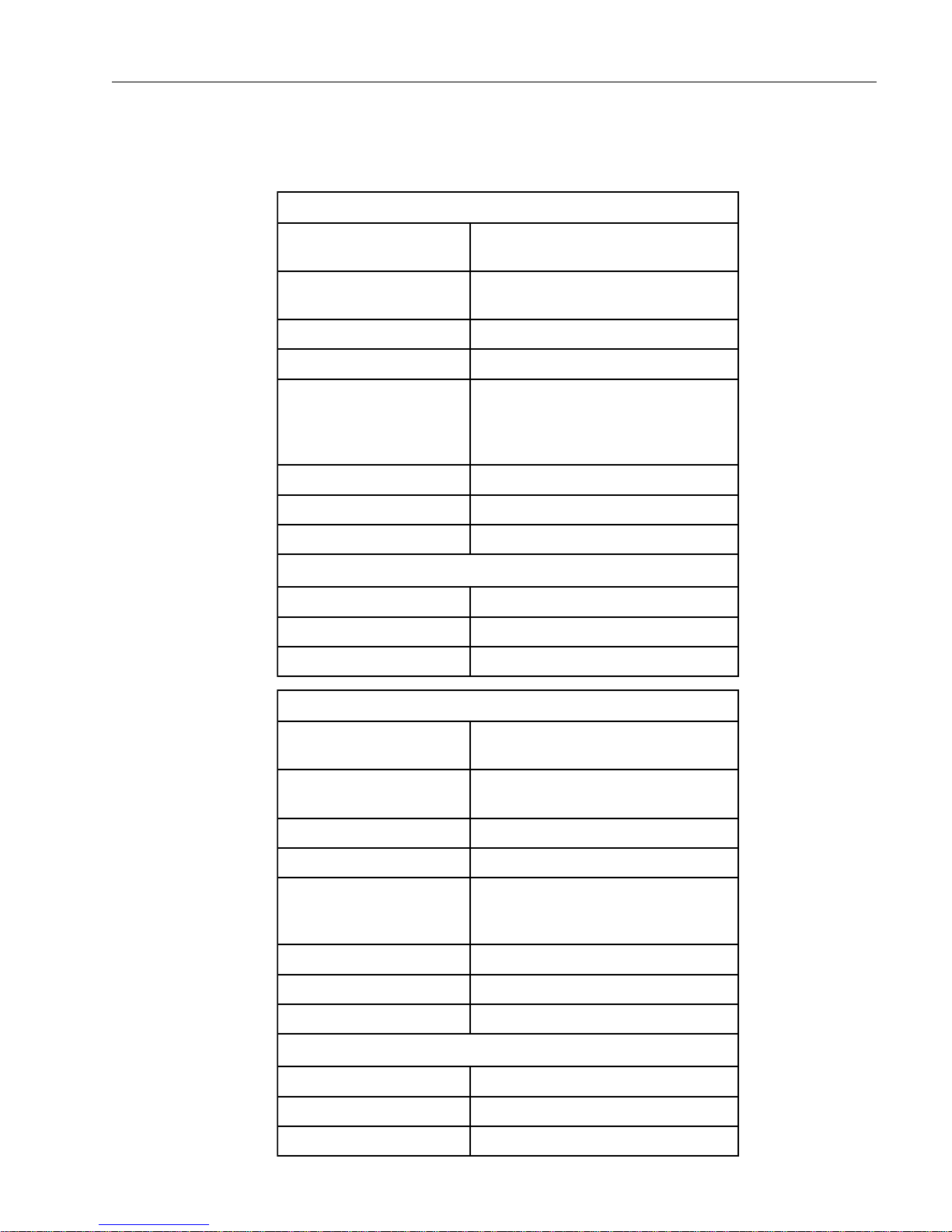
General Specifications
0055CEledoM
eziStenibaC
eziSrebmahC
thgieW)gk8.62(.sbl95
egattaWretaeHW008
gnitaRlacirtcelE
erusserPgnitarepO)aPk672-831(gisp04-02
erutarepmeTnoitarepO231 ° 072(C ° )F
evlaVfeileRerusserP)aPk013(gisp54
seiticapaCdiulF
riovreseRnoituloS).zo.lf73(sretil1.1
knaTetasnednoC).zo.lf73(sretil1.1
rebmahCtohS).zo.lf10.1(lm03
D"5.81xH"31xW"57.61
)mm074xmm033xmm524(
peed"52.31xretemaid"8
)mm733xmm302(
spmA01,zH05,CAV001
spmA01,zH06,CAV001
spmA8,zH06,CAV511
spmA4,zH05,CAV032
0006CEledoM
eziStenibaC
eziSrebmahC
thgieW)gk4.45(.sbl021
egattaWretaeHW0021
gnitaRlacirtcelE
erusserPgnitarepO)aPk672-831(gisp04-02
erutarepmeTnoitarepO231 ° 072(C ° )F
evlaVfeileRerusserP)aPk013(gisp54
seiticapaCdiulF
riovreseRnoituloS).zo.lf73(sretil1.1
knaTetasnednoC).zo.lf73(sretil1.1
rebmahCtohS).zo.lf30.2(lm06
D"5.02xH"5.61xW"52.91
)mm125xmm914xmm984(
peed"61xretemaid"01
)mm604xmm452(
spmA31,zH06,CAV001
spmA21,zH06,CAV511
spmA6,zH05,CAV032
5

General Description
Controls and Features
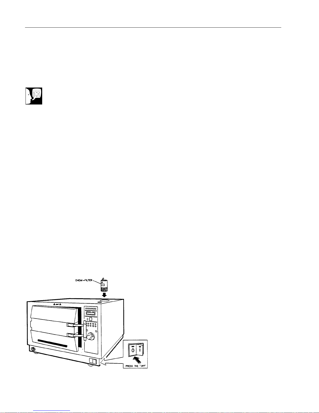
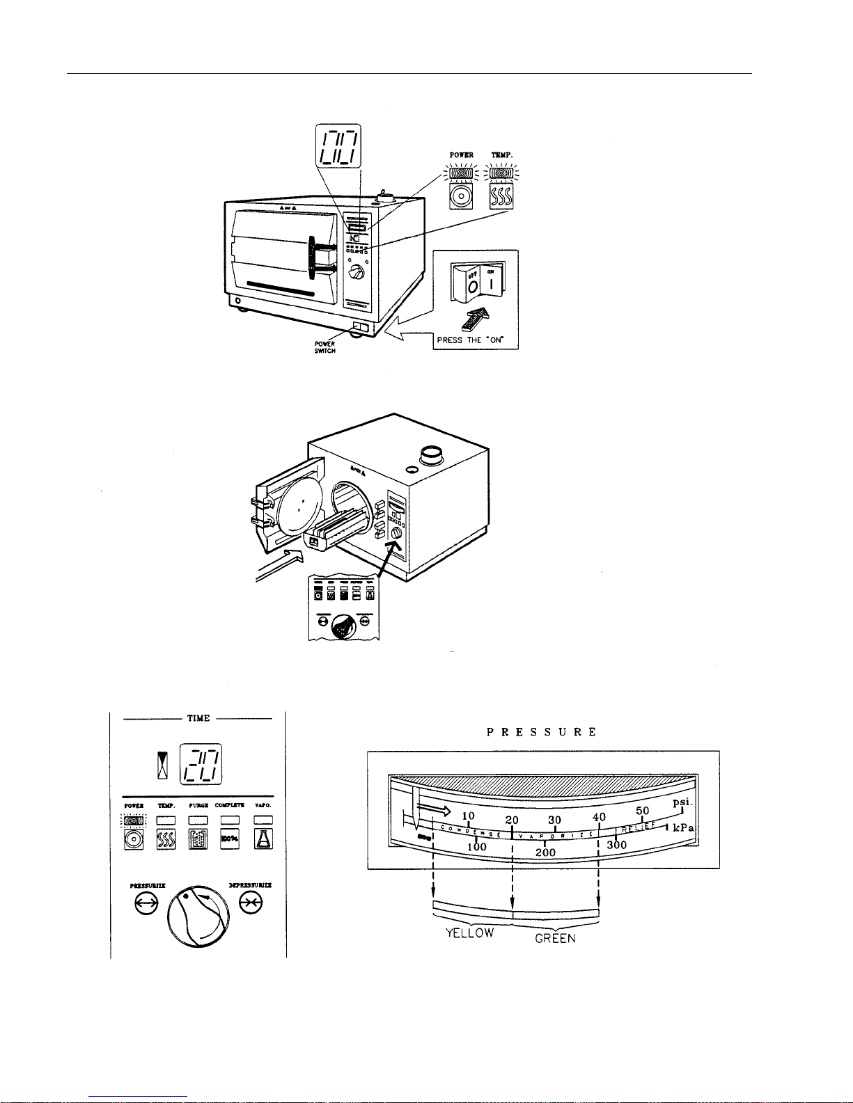
Power Switch
The power switch on the front of the sterilizer turns power
to the sterilizer ON (I) or OFF (O). See Figure 1.
Control Panel
Pressure Gauge
Displays the chamber pressure. See Figure 2.
Timer
Times the 20 minute exposure phase and the purge phase
for models EC5500 and EC6000.
Indicators
POWER: Lights when power to the unit is ON.
TEMP: Turns on and off as the chamber heaters cycle on
and off.
COMPLETE: Lights when the exposure phase is complete.
PURGE: Lights when the chamber is being emptied of
vapors.
VAPO: Signals when the reservoir must be filled with VapoSteril solution. The indicator will remain lit until solution is
added.
CONTROL KNOB: Attached to the valve shaft, this knob
controls the metering valve. Turning the control knob to
PRESSURIZE introduces VAPO-Steril into the chamber
and enables a cycle to begin. Turning the knob to DEPRESSURIZE permits vapors to exhaust from the chamber.
Figure 2: Control Panels—EC Series
6
GENERAL DESCRIPTION
Sterilant
Level Switch
Pressure
Switch
Pump
Condensate
Tank
Drain
Exhaust to
Chemi-filter
Door
Cover
Door
Handle
Pressure
Relief Valve
Door
Latch
Air filter
From
Condenser
Seal
Screws
Door
Door
Gasket
Baffle Plate
Chamber
Chemi-filter
Filling
Cup
Valve Shaft
Switch
Reservoir
Filter Housing
Exhaust to
Chemi-filter
Metering
Valve
Power
Cord
Main fuse
holder
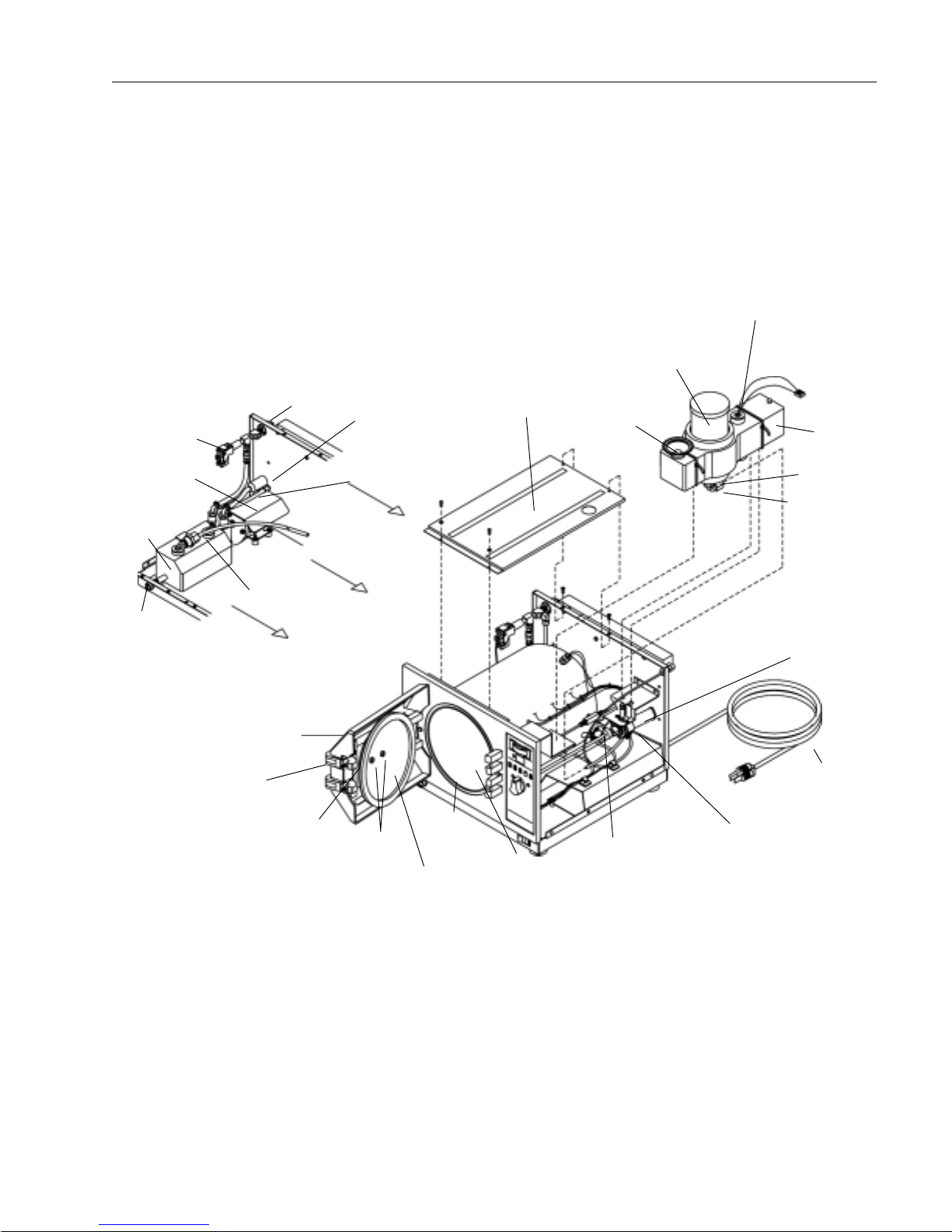
Figure 3: Major Components
7
GENERAL DESCRIPTION
Chemi-Filter
The Chemi-Filter is placed in the top of the sterilizer. It
removes chemicals from the exhaust.
Door
The door latch secures the door. It is opened by the door
handle. The handle mechanism prevents the door from
being opened while there is pressure in the chamber.
Drain
A drain valve below the sterilizer door is provided to drain
used Vapo-Steril from the condensate tank.
Caution
Be sure you are using only Harvey
Vapo-Steril solution. Other solutions will
cause damage to the Chemiclave and
will void all warranties.
Pressure Relief Valve
A safety valve on the rear of the sterilizer relieves excess
chamber pressure (see Figure 3).
Piping Components
See Figure 3 for major components and Figure 12 for
detailed component locations.
Reservoir
The reservoir holds about 1 liter of Vapo-Steril solution (see
“Technical Specifications” for exact amounts). The filling
cup has a spring-loaded valve. When the reservoir is full,
the valve stops the flow of solution from the filling bottle.
The reservoir contains a STERILANT LEVEL SWITCH.
This switch lights the VAPO indicator on the control panel
when the level of solution is low.
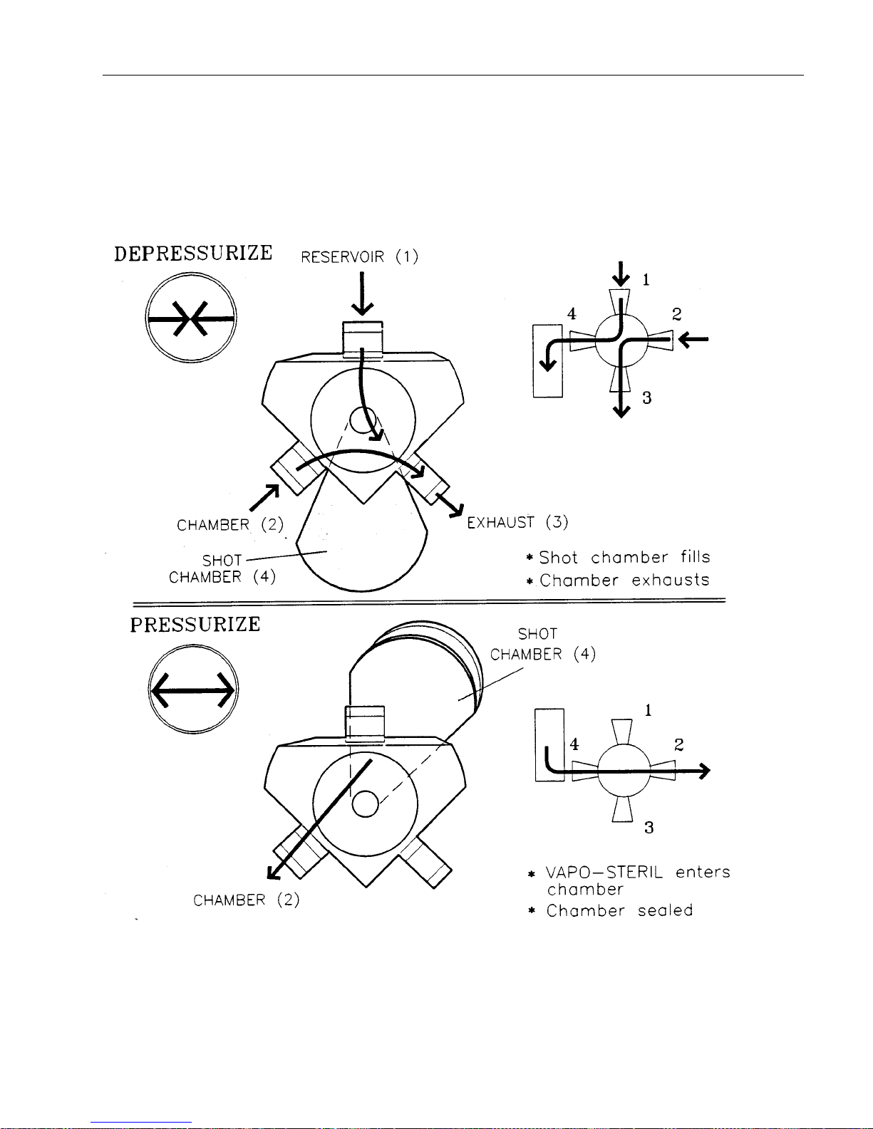
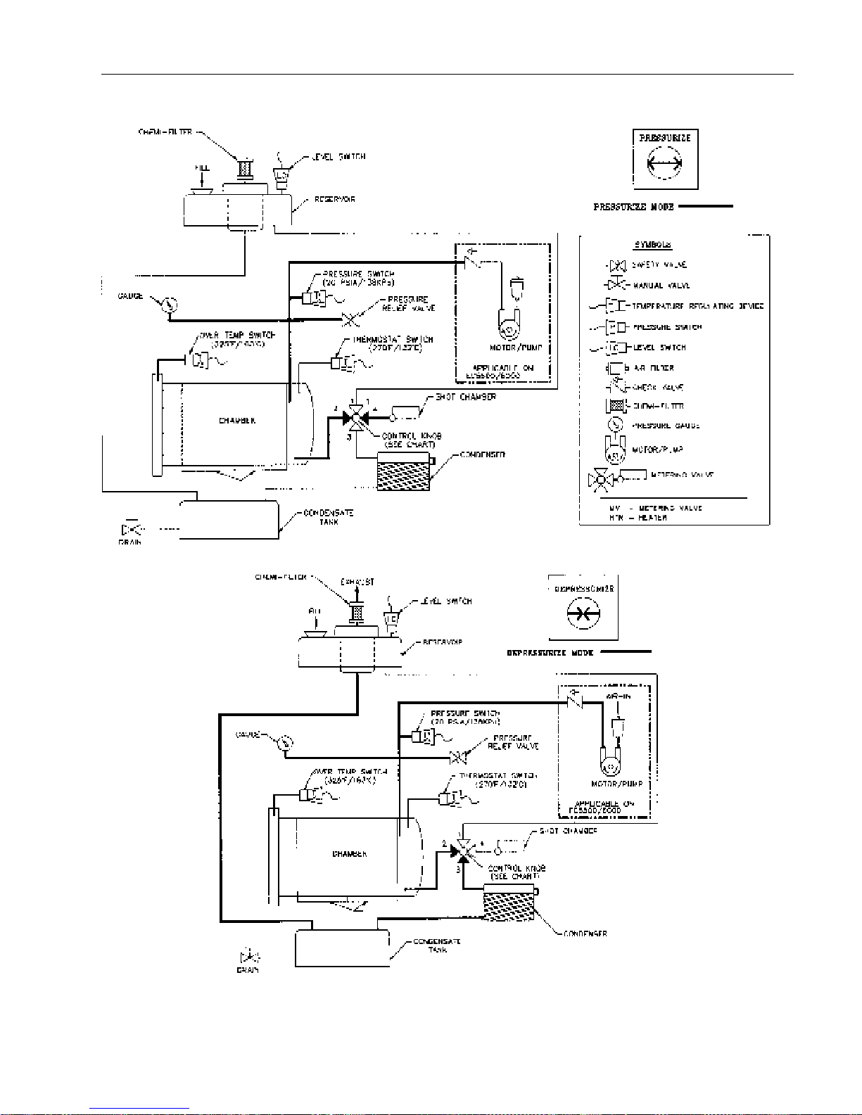
Metering Valve
8
Operated by the control knob, the valve has four ports
(including the shot chamber) and two settings, DEPRESSURIZE and PRESSURIZE.

GENERAL DESCRIPTION
With the control knob at DEPRESSURIZE, Vapo-Steril
can enter through the fill port and fill the shot chamber,
while the chamber itself connects through the exhaust
port to the exhaust line.
With the control knob at PRESSURIZE, the fill port and
exhaust port are closed. The valve connects the shot
chamber to chamber. The measured amount of VapoSteril from the shot chamber can enter the chamber. The
chamber can build pressure to run a sterilizing cycle.
Chamber
Pressure vessel where loads of instruments are sterilized. The pressure for a typical sterilizing cycle is 20 - 40
psig (138 - 276 kPa).
Pressure Gauge
Displays the chamber pressure.
Pressure Relief Valve
The pressure relief valve will open to relieve the chamber
pressure if it exceeds the pressure rating of the valve.
This valve is on the rear of the sterilizer.
Condenser
The condensing coils on the back of the sterilizer liquefy
the vapors that exit from the chamber.
Condensate Tank
The condensate tank collects the liquefied vapors from
the condenser. Any remaining vapors proceed through
the exhaust line to the Chemi-Filter.
Drain
The drain includes a valve in the chassis and a separate
fitting with plastic tubing. The operator inserts the fitting
into the valve to empty liquid waste from the condensate
tank.
9

GENERAL DESCRIPTION
Exhaust
Vapors from the chamber that do not liquefy in the condenser proceed to the exhaust connection on the filter
housing. They exit through the Chemi-Filter into the atmosphere.
Chemi-Filter
The Chemi-Filter traps the formaldehyde from the exhaust
vapors before releasing them to the atmosphere. The
Chemi-Filter should be installed before the sterilizer is
operated. It must be replaced regularly.
Pump
Propels air into the chamber during the purge phase, which
forces vapors out of the chamber through the vent port.
Air Filter
Removes contaminants from intake air before the pump
propels it into the chamber.
Check Valve
Prevents chamber back pressure from contacting the pump
and the air filter.
Electrical Components
Printed Circuit Boards (PCBs)
Power Supply Board
Transforms line power into working voltages. Acts as “input/
output” board for heater and pump.
10
GENERAL DESCRIPTION
Display Control Board
Contains logic circuits and display components, including
the timer and the buzzer.
• Timer: On Display/Control Board. Counts to
time the exposure and purge phases. For the
exposure phase, the timer operates only if the
valve shaft switch is closed and the pressure
switch is closed. For the purge phase, the
timer is actuated when the control knob is
turned to DEPRESSURIZE and valve shaft
switch changes from closed to open. After a 1minute delay, the timer begins to count down
the preset purge valve.
• Buzzer: On Display/Control Board. Signals the
end of the exposure and purge phases.
Power Cord
The power cord connects the unit to the voltage supply.
Power Switch
The POWER switch turns ON and OFF the electrical
power for the unit.
Control Panel
The control panel contains the indicators, pressure gauge
and the control knob.
Heater
The chamber is heated by a band-type heater that wraps
completely around the outside of the chamber. Wattage
for the heater is listed in “Technical Specifications.”
Caution
Refer to “Thermostat Adjustment” in the
“Maintenance and Servicing” section of
this manual before adjusting the
thermostat.
Thermostat
Turns heater on and off to maintain chamber temperature.
11

GENERAL DESCRIPTION
Overtemp Switch
Opens to cut power to the heaters if chamber temperature
reaches (163°C ± 4) 325°F. Overtemp switch has to be
manually reset.
Valve Shaft Switch
Engaged by the cam on the valve shaft, this switch is
closed only when the control knob is set to PRESSURIZE.
For the exposure phase, the timer will not operate if either
this switch or pressure switch is open. For the purge phase,
this switch must change from the closed state to the open
state. After a 1-minute delay, the timer begins to count
down the preset purge value.
Pressure Switch
Closes when chamber pressure reaches the minimum
exposure pressure of (138 kPa) 20 psi. Opens whenever
chamber pressure is less than that value. For the exposure
phase, the timer will not operate if either this switch or value
switch is open.
Sterilant Level Switch
The sterilant level switch in the reservoir lights the VAPO
indicator when the sterilant level is low. This switch is
preset to actuate when one liter of Vapo-Steril can be
poured into the reservoir. The float level is not adjustable.
12
Principles of Operation
Warning
Do not reuse Vapo-Steril solution
removed from the waste tank. This
liquid may be contaminated or
chemically altered and may damage
the sterilizer.
Caution
Use only harvey Vapo-Steril solution in
the Chemiclave. Do not dilute, alter or
otherwise change Vapo-Steril in any
way. Use of other solutions may cause
mechanical damage to components of
the sterilizer and may result in nonsterile loads.
Chemiclave Cycle
(EC5500 & EC6000)
Filling the Reservoir
This is a manual function. When the sterilant reservoir is
filled, Vapo-Steril can flow through the metering valve to
fill the shot chamber. The metering valve is open to the
shot chamber when the control knob is set to DEPRESSURIZE (see Figure 4).
Power On
Control knob is set to DEPRESSURIZE before turning
the power ON. This vents any sterilant vapors into the
condensate tank. Electrical power is applied to the unit
when POWER switch is turned ON. When the power is
turned ON all the indicator (LED’s) should light for
approximately two seconds then extinguish, except for
the POWER and TEMP indicators which should remain
ON.
Warm Up
The heater that surrounds the chamber is turned on
when the power is turned ON. It stays active until the
setpoint temperature is reached. As long as the heater is
active, the TEMP indicator lights (see Figure 5).
Ready/Load
When the setpoint temperature is reached, the heater
cycles off and the TEMP indicator goes out. The chamber
is ready to be loaded (see Figure 6). The heater is
controlled to maintain chamber temperature. TEMP light
cycles on and off with heater.
Pressurization
When the operator sets control knob to PRESSURIZE,
sterilant flows by gravity into the chamber from the shot
chamber of the metering valve (see Figure 7, PRESSURIZE mode). Chamber pressure begins to increase. The
timer displays “20” minutes.
13
PRINCIPLES OF OPERATION
Exposure
This timed function begins when chamber pressure reaches
20 psig (138 kPa). Pressure switch is then energized. The
timer counts down the exposure time of 20 minutes. The
decimal point flashes when the timer is active. Chamber
pressure is displayed continually on the pressure gauge. If
pressure goes below 20 psig (138 kPa), the pressure
switch is de-energized. This stops the timer countdown and
the flashing decimal point until pressure returns to 20 psig
(138 kPa) or above.
Note
Exposure conditions are maintained
until the control knob is set to depres-
surize.
Exposure Complete
When the exposure is complete, the timer displays “00” and
a tone sounds. The COMPLETE indicator lights. The
PURGE indicator flashes briefly (see Figure 9).
Depressurization
Begins when the operator sets the control knob to DEPRESSURIZE (see Figure 4). This vents the chamber
through the metering valve to the condensate tank (see
Figure 8, DEPRESSURIZE mode). Pressure switch is deenergized. The COMPLETE indicator stays on. The
PURGE indicator continues to flash as the chamber
depressurizes for one minute.
Purge
Begins automatically after Depressurization (approximately
1 minute delay before pump starts). See Figure 10. Timer
displays “07” (EC5500) or “09” (EC6000). The COMPLETE
indicator goes out. The PURGE indicator lights. Purge
pump forces sterilant vapor from the chamber until the timer
counts down to “00.”
14
Complete
After Purge, the pump stops and the PURGE indicator goes
out. A tone sounds. The pressure gauge reads less than 2
psig (14 kPa). The cycle is complete. The COMPLETE light
stays lit for one minute, then goes out. Heater remains
controlled as long as the POWER switch remains ON. The
POWER indicator is lit and he TEMP indicator cycles on
and off with the heater. To unload, the operator opens the
door (see Figure 11).
PRINCIPLES OF OPERATION
Figure 4: Metering Valve Function
15
PRINCIPLES OF OPERATION
Figure 5: Warm-Up
Figure 6: Ready/Load
Figure 7: Pressurization
16
PRINCIPLES OF OPERATION
Figure 8: EC5500/EC6000 Operation
17
 Loading...