

HARVEY C200, C200-30 Operating Instructions Manual

Contents
1. Foreword
2. Warranty Information
3. Machine Description
3.1 Technical Parameters
3.2 Features Identification
3.3 Optional Equipments
3.4 Intended Use
3.5 Requirements of Electrical Power
4. Safety Regulations
4.1. General Safety Instructions
4.2. Specific Safety Instructions for Sliding Table Saw
4.3. Residual Risks
4.4.Safety Equipments
5. Installation of the Machine
5.1 Transportation of Machines
5.2 Unpacking
5.3 Contents of C200-30
5.4 Safety Measure before Installation
5.5 Installation
6. Adjustment
6.1 Blade Elevation and Tilting Mechanism
6.2 Adjusting Rip Fence
6.3 Aligning Table T-slot Parallel with Blade
6.4 Adjusting 45°and 90°Positive Stops
6.5 Aligning Blade Guard Splitter or Riving Knife with Blade
7. Operations
7.1 Electrical Operation
7.2 Safety Precautions before Operations
7.3 Operation
7.4 Crosscutting
7.5 Ripping
8. Maintenance
9. Trouble Shooting
10. Exploded View and Parts List
...............................................................................................................................................
.........................................................................................................................
..........................................................................................................................
.................................................................................................................
.................................................................................................................
...................................................................................................................
................................................................................................................................
.............................................................................................
.............................................................................................................................
.......................................................................................................
............................................................................................................................
......................................................................................................................
...............................................................................................................
........................................................................................................
.....................................................................................................................................
...................................................................................................................
...........................................................................................
...................................................................................................................................
.........................................................................................................................................
.................................................................................
..................................................................................................................
...............................................................................
.......................................................................................
..........................................................................................................................................
...................................................................................................................
...................................................................................
....................................................................................................................................
................................................................................................................................
........................................................................................................................................
.......................................................................................................................................
..............................................................................................................................
.....................................................................................................
................................................................
....................................................
1
1
2
2
3
3
4
4
5
5
5
6
6
7
7
8
9
9
10
15
15
15
15
16
16
17
17
17
17
17
17
18
19
20

1. Foreword
2. Warranty Information
This machine contains basic information for
qualified operators and describes the intended
uses of the machine. It contains all of the
information necessary for correct and safe
operation. The machine is equipped with various
safety features which will protect the operator
under normal operating conditions. This
information cannot cover all possible safety
aspects and that is why the operator needs to
review this manual and insure familiarity with it and
its functions before operating it.
Limited Warranty
Two year.
Proof of Purchase
Please keep your dated proof of purchase for
warranty and servicing purposes.
Limited Tool Warranty
We make every effort to ensure that this product
meets high quality and durability standards. We
offer a two-year limited warranty based on the
purchase date. Defective parts will be repaired or
replaced by Harvey at no charge. Warranty does
not apply to defects due directly or indirectly to
misuse, abuse, normal wear and tear, negligence
or accidents, repairs done by an unauthorized
service center, alterations and/or lack of
maintenance. We shall in no event be liable for
death, injuries to persons or property or for
incidental, special or consequential damages
arising from the use of our products. To take
advantage of this limited warranty, contact us at
888-211-0397 or info@harveywoodworking.com.
We will either repair or replace the product if any
part or parts covered under this warranty, after
examination, proves to be defective in
workmanship or material during the warranty
period.
Notice to California Residents: This product can
expose you to wood dust, which is known to the
State of California to cause cancer. For more
information, go to www.P65Warnings.ca.gov.
1

3. Machine Description
3.1 Technical Parameters
Model: C200-30
ITEM C200-30
Product
Dimensions
Electrical Switch Magnetic with Thermal Overload Protection
Power
Supply
Motor
Blade
Information
Weight 180Kg 396 lbs
Length/Width/Height 1570x985x1060 mm 61-13/16"×38-3/4"×41-3/4"
Footprint 514x498 mm 20-1/4"×19-5/8"
Horsepower, Voltage,
Frequency, Phase, Amps
Type TEFC, Capacitor Start, Induction
Speed 3500 RPM
Power Transfer V-Ribbed Belt Drive
Maximum Blade Diameter 254 mm 10”
Riving Knife Thickness 2.5 mm 0.1”
Available Blade Plate Thickness 1.8-2.4 mm 0.071”-0.094”
Available Blade Kerf Thickness 2.6-3.2 mm 0.102”-0.126”
Maximum Width of Dado 20.6 mm 13/16"
Blade Tilt Left 0-45°
Arbor Diameter at Blade 15.875 mm 5/8”
1.65 kW, 230 V,
50 Hz, 1 PH, 8 A
2.0 HP, 115 V (230 V), 60 Hz,
1PH,16A(8A)
Cutting
Capacities
Table
Information
Miter
Gauge
Other
Information
Arbor Speed 3850 RPM
Arbor Bearings Sealed and Permanently Lubricated
Maximum Depth of Cut at 90° 79.4 mm 3-1/8”
Maximum Depth of Cut at 45° 56 mm 2-3/16”
Maximum Rip, Right of Blade 800 mm 31-1/2"
Maximum Rip, Left of Blade 288 mm 11-3/8"
Height 867 mm 34”
Main Table -
512x685x40 mm 20"×27"×1-1/2"
Length/Width/Thickness
TableSizeWithExtension
1016x685 mm 40"×27"
Wings--Length/Width
Miter Gauge Slot Type T-Shape
Miter Gauge Size - Width/Height 19x9.5 mm 3/4” x 3/8”
Finish Powder Coated
Dust Port Size 100 mm 4”
Note: For correct option of power supply, please refer to the specifications label on the product.
2
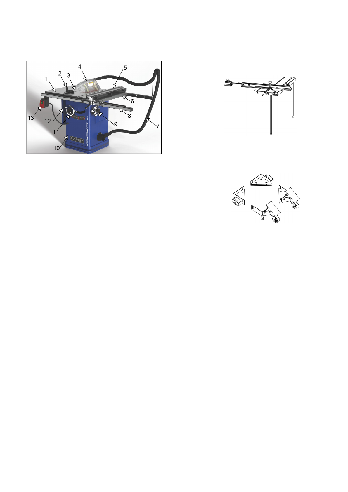
3.2 Features Identification
Refer to Fig. 1.
Fig. 1
3.3 Optional Equipments
Sliding table
Model: ST-1400S
Fig. 1-1
Universal Mobile Base
Model: MB-600
1 Left Extension Table
2MiterGauge
3 Main Table
4 Blade Guard
5 Fence
6 Right Extension Table
7Flexiblehose
8 Rail & Tube
9 Blade Elevation Hand Wheel
10 Cabinet
11 Blade Tilt Hand Wheel
12 Motor Cover
13 On/Off Switch
Fig. 1-2
3

3.4 Intended Use
The table saw and the fence supplied with it are
intended to be used exclusively for the following
purposes:
● Laminated and unlaminated board materials (e.g.
chipboard, coreboard, MDF board, ...)
● Solid wood
● Gypsum plasterboard, Cardboard, Veneer with a
suitable clamping device
● Dimensionally stable plastics (thermoset plastics,
thermoplastics). Sawing these materials does not
normally involve any risks in respect of dust, chips,
and thermal degradation products.
Too ls:
● The chosen saw blade must be suitable both for
the specific work cycle and for the specific material.
●Only circular blades which are solid chrome
vanadium (CV) or tungsten carbide tipped (TCT)
andhaveadiameterof
( 15.875mm ) ,aswellasamaximumwidthof
13/16"(
● Saw blades and their fixing devices shall conform
to EN 847-1:2005.
10”(254mm), arbor size 5/8”
20.6mm)are allowed for the main saw
The machine is prohibited to be used in a
potentially explosive atmosphere!
3.5 Requirements of Electrical Power
List of the motor using & pre-wired voltage
Item
2HP 1.65kW
Voltage(V) 115(230 V) 230 V
Phase 1 PH 1 PH
Freq.(Hz) 60Hz 50Hz
Rated current A 16(8)A
Prewired 115 V/1 PH 230 V/1 PH
Note: For correct option of power supply, please
refer to the specifications Label on the product.
The recommended amperage of the power supply
line is 20 A.
The steady-state AC power supply is 0.9 -1.1 times
of the rated value.
Motor
8A
Site of installation/use:
● The machine is not suitable for use outdoors, or in
rooms that are subject to moisture or the risk of
explosions.
●The intended use of the machine involves
connection to a suitably dimensioned chip and dust
extraction system .
● Intended use also involves compliance with our
specified operat ing, maintenance and repair
conditions and the safety information contained in
the operating instructions.
● The table saw may only be used, set up and
maintained by persons who are familiar with the
machine and aware of the dangers.
● The pertinent accident prevention regulations as
well as any other generally recognized technical and
industrial safety rules must be observed.
● Repair work must be carried out by our own
customer service or by an organization that we have
authorized to repair tools. Only original spare parts
are allowed. We will assume no warranty for any
damage that is caused by using non-original spare
parts.
Electrical Protection
End user should provide protection device against
overvoltage due to lightning and short-circuited
protection device at the power supply.
Ingress P rotection at the Inlet of Incoming
Power Cable
The method of the incoming cable should ensure
IP54 protection class when installation is finished.
4

4. Safety Regulations
4.1 General Safety Instructions
1. KNOW YOUR MACHINE.
Read and understand the owners manual and
labels affixed to the machine. Learn its application
and limitations as well as its specific potential
hazards;
2. GROUND THE MACHINE.
In the event of an electrical short, grounding
reduces the risk of electrical short;
3. KEEP THE BLADE GUARDS IN PLACE.
Keep in good working order, properly adjusted and
aligned;
4. REMOVE THE ADJUSTING TOOLS
Form a habit of checking that the key and adjusting
wrenches are removed from the machine before
turning it on;
5. KEEP THE WORK AREA CLEAN.
Cluttered areas and benches invite accidents.
Make sure the floor is clean and not slippery due to
wax and sawdust build-up;
6. AVOID A DANGEROUS ENVIRONMENT.
Don’t use machines in damp or wet locations or
expose them to rain. Keep the work area well lit
and provide adequate surrounding work space;
7. KEEP CHILDREN AWAY.
All visitors should be kept a safe distance from
work area;
8. MAKE WORKSHOP CHILD-PROOF.
With padlocks, master switches or by removing
starter keys;
9. USE THE PROPER SPEED.
A machine will do a better and safer job when
operated at the proper speed;
10. USE THE RIGHT MACHINE.
Don’t force the machine or the attachment to do a
job for which it was not designed;
11. WEAR THE PROPER APPAREL.
Do not wear loose clothing, gloves, neckties or
jewelry (rings, watch) because they could get
caught in moving parts. Non-slip footwear is
recommended. Wear protective hair covering to
contain long hair. Roll up long sleeves above the
elbows;
12. MAINTAIN PROPER FOOTING.
Keep proper footing and balance at all time. Do
not over-reach to perform an operation;
13. MAINTAIN THE MACHINE WITH CARE.
Keep tools sharp and clean for the best and safest
performance;
14. DISCONNECT MACHINES.
Before servicing, when changing accessories or
attachments;
15. AVOID ACCIDENTAL STARTING.
Make sure the switch is in the “OFF” position
before plugging in;
16. USE RECOMMENDED ACCESSORIES.
Consult the manual for recommended accessories.
Follow the instructions that accompany the
accessories. The use of improper accessories may
cause hazards;
17. NEVER STAND ON THE MACHINE.
Serious injury could occur if the machine tips over.
Do not store materials such that it is necessary to
stand on the machine to reach them;
18. CHECK FOR DAMAGED PARTS.
Before further use of the machine, a guard or other
parts that are damaged should be carefully
checked to ensure that they will operate properly
and perform their intended function. Check for
alignment of moving parts, breakage of parts,
mounting, and any other conditions that may affect
its operation. A guard or other parts that are
damaged should be properly repaired or replaced;
19. NEVER LEAVE THE MACHINE RUNNING
UNATTENDED.
Turn the power to "off". Do not walk away from the
machine until it comes to a complete stop;
20. ADEQUATE LIGHT
Ensure that adequate general or localized lighting
is provided in work area;
4.2 Table Saw Safety Instructions
1. ALWAYS USE A GUARD.
Always use a guard 、 splitter and anti-kickback
fingers on all “thru-sawing” operations.
Thru-sawing operations are those when the blade
cuts completely through the work piece as in
ripping or crosscutting;
2. ALWAYS HOLD THE WORK.
Always hold the work firmly against the miter
gauge or fence;
3. ALWAYS USE A PUSHSTICK OR PUSH
BLOCKS.
Push blocks or push sticks shall be used when
cutting small workpieces and in circumstances
where it is necessary to push the workpiece
against the fence;
4. NEVER PERFORM UNSAFE OPERATIONS.
Never perform any operations “free-hand” which
means using your hands to support or guide the
work piece. Always use either the fence or the
miter gauge to position and guide the work piece;
5
5. STAND TO THE SIDE WHEN FEEDING
MATERIAL.
Never stand or have any part of your body in line
withthepathofthesawblade;
6. USE CAUTION WHEN REACHING FOR
OBJECTS.
Never reach behind or over the cutting tool with
either hand for any reason;
7. SAFE CROSSCUTTING OPERATIONS.
Move the rip fence out of the way when
crosscutting;
8. ENSURE CORRECT FEEDING OF MATERIAL.
Feed the work into the blade against the direction
of rotation;
9. CORRECT USAGE WITH THE FENCE.
Never use the fence as a cut-off gauge when you
are cross-cutting;
10. ALWAYS TURN THE POWER TO THE "OFF"
POSITION.
When attempting to free a stalled saw blade,
always turn the saw to the "off" position and
disconnect it from the power source.
11. PROVIDE ADEQUATE SUPPORT.
To the rear and sides of the table saw for wide or
long work pieces;
12. AVOID KICKBACKS.
Avoid kickbacks (work thrown back towards you)
by keeping the blade sharp, by keeping the rip
fence parallel to the saw blade, by keeping the
splitter and anti-kickback fingers and guard in place
and operating, by not releasing work before it is
pushed all the way past the saw blade, and by not
ripping work that is twisted or warped or does not
have a straight edge to guide along the fence;
13. AVOID AWKWARD OPERATIONS.
Avoid awkward operations and hand positions
where a sudden slip could cause your hand to
move into the spinning blade;
14. BLADE REQUIREMENTS.
Only correctly sharpened saw blades
manufactured in accordance with the requirements
of EN 847-1:2005 shall be used;
15. CORRECT SAW BLADE USAGE.
No saw blade shall be used where the maximum
marked speed is lower than the maximum
rotational speed of the saw spindle;
16. CHIP AND DUST.
The mac hine shall be connected to an external
chip and dust extraction system;
The dust extraction equipment is to be switched on
before commencing machining;
17. CHECK
Periodically check the brake function to make sure
the completed stop time of the saw blade is less
than 10 seconds.
4.3 Residual Risks
1. Take precautions to reduce the hazard of
inhalation of harmful dusts (e.g. wearing a dust
mask);
2. Wear ear protection to prevent hearing loss;
3. Always wear safety glasses. Also use a face
or dust mask if t he cutting operation is dusty;
4. Protect against the hazard of handling saw
blades when doing maintenance;
5. Do not attempt to remove chips while the
blade is still moving;
6. Do not use the machine unless all of the
guards and other safety devices necessary for
machining are in good working order;
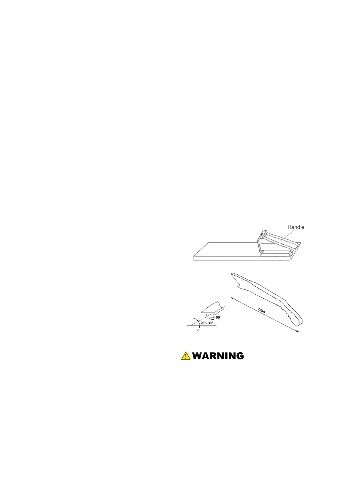
4.4 Safety Equipments
Apushblock(Fig. 2) and A push stick (Fig. 3)
must be used
Fig. 2
Fig. 3
If the workpieces is less then 120 mm, you
must use the push stick to prevent your hands
from getting too close to the saw blade.
Push block must be used to cut narrow
workpieces and, when necessary, to push the
workpiece against the fence. A push block can
be easily made by the operator as shown in Fig.
2.
6

5. Installation of the Machine
5.1 Transportation of Machines
5.1.1 Transportation and Storage
Anti-rust and shock-proofing measures were taken
during packaging. The machine is able to endure
temperature variations of -13 to 130 degrees F. Do
not expose the machine to rain and avoid
damaging the packaging during transportation and
storage.
5.2 Unpacking
Your machine was carefully packaged for safe
transportation. R emove the packaging materials
from around your machine and inspect it. If you
discover the machine is damaged, please
immediately call Customer Service for advice.
Save the containers and all packing materials for
possible inspection by the carrier or its agent.
Otherwise, filing a freight claim can be difficult.
While transporting or handling the machine, be
careful and let the activity be done by qualified
personnel especially trained for this kind of
activity!
While the machine is being loaded or unloaded,
make sure that no person or subject gets
injured by the machine!
Select proper transportation device according
to the weight of the machine. Make sure the
lifting capacity of the transportation device is
competent for the weight of the machine.
5.1.2 Transportation before unpacking
As standard, the machine is packed in a robust
cardboard box. Fig. 4 shows the tool can be used
to transport the packing box.
Note: If you can't find an item on this list, check
the mounting location on the machine or
examine the packaging materials carefully.
Occasionally we pre-install certain components
for shipping purposes, or in other packing;
Fig. 4
7
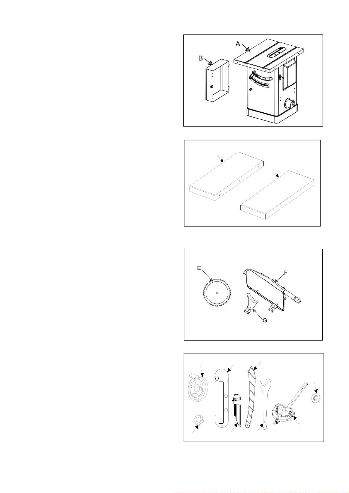
5.3 Contents of C200-30
Main machine box contents:
(Fig. 4-1-----Fig. 4-4)
A. Main table saw unit……..………..………1
B. Motor cover……….……..………..………1
C. Left extension table……..………………1
D. Right extension table…………………1
E. Saw blade…………………………………1
F. Blade guard assembly…………………1
G. Rivin g knife…….. ……….. …….. ……… 1
H. Hand wheel……………..………..………1
I. Lock knob..….. ………..………..………1
J. Hex wrench set (eight pieces)…..…1
K. Wrench open-end 17/23 mm…..………1
L. Miter gauge…..………..…..…..………1
M. Dado Blade Flange…………………….1
N. Push stick…..…… .. …..……… ..……… 1
O. Dado table insert……..………..……… 1
Fig. 4-1
C
D
Fig. 4-2
Fig. 4-3
H
O
N
M
8
I
Fig. 4-4
L
J
K
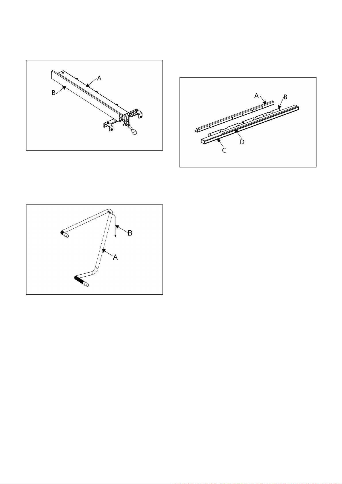
Fence box contents:(Fig. 4-5)
A. Fence body…..…..……………… ..……1
B. Fence………………………………..…..1
Fig. 4-5
Rail box contents:(Fig. 4-7)
A. Rear rail…………… ..……………..…… 1
B. Front rail…………….…………..………1
C. Front rail rectangular tube………...…1
D. Front rail tape scale………………….…1
Flexible hose box contents:(Fig. 4-6)
A. Flexible hose (length 2.5 m)…………...1
B. Hose bracket ……………………………..1
Fig. 4-6
Fig. 4-7
5.4 Safety Measure before Installation
It is important to maintain a free area of 2.5 ft.
around the machine, which is required for the
working place. If any long material is machined, it is
necessary to have a sufficient room in front of the
machine as well behind it in the places of material
input and output.
9
 Loading...