

Harvest TEC 720 Owner's Manual
Model 720 Dew Simulator Owner’s Manual -18
5/18
Owner’s Manual
Model 720 Dew Simulator
Natural Dew Simulation Machine
1

(intentionally blank)
2

Model 720 Dew Simulator Table of Contents
Page
Introduction
5
Requirements
5
Safety
6
Safety Decal Definitions
6
Safety Decal Locations
7
Setup
8-12
Unloading the Machine
8
Connecting the Reel
9
Connecting Hoses
10
Connecting Perimeter Nozzle Hoses
10
Preparing the Water Supply Trailer
11
Hooking up Tractor, Dew Sim & Trailer Tank
12
Machine Setup
13-18
Installing Tines & Tips
13
Tine Assemblies
13
Tip Rate Chart – MW5 & MW11 Tips
14
Drive Chain
15
Trip Sections
16
Adjusting Trip Sections
16-17
Operating Perimeter Nozzles
17
Perimeter Nozzle GPM
18
Description of Electronic Valves and Sensors
18-19
2Way Valve
18
Warming Valve
18
Arm Switch
19
Installing Controls
20
Wiring Diagram
20
Initial Operation
21-22
Turning on the Dew Simulator
21
Priming the System
21
Determining Operation Settings
21-22
Setting Pressures
22
Warming Up Systems
22
Operating
22-28
Control Box
23
Screen Definitions
23
Field Setup Screen Steps
24
Minimum and Maximum Levels
24
Main Screen
25
Heater #1 & #2
26
Arm Override
26-27
Warming Valve
27
Operating Temp Status
27
Target PSI
28
Target GPM
28
Operation of the Dew Simulator
28-31
Removal of the Ground Drive Chain
29
Field Operation
29
Using Surfactant
30
Maintenance
30
3

Maintenance Schedule
30
Preventative Maintenance
30
Maintenance Details
30
Heater Coil Descaling Procedure
31
Winterizing Procedures
32
Troubleshooting
33-36
Pin Outs
36-41
Parts Breakdown
42-59
Tine Assembly
42
Valve Assembly
42
Valve Exploded View
43
Valve Trip Assembly
43
Cross Tube Assembly
44
Trip Assembly
44
Cam Mount Assembly
45
Reel Dumbbell Assembly
45
X-Tube Bearing Assembly
46
Perimeter Nozzle Pump Assembly
46
Perimeter Nozzle Pump Feed
47
Perimeter Nozzle Assembly
47
Reel Assembly
48
Lift Arm Assembly
49
Lift Arm Support Assembly
49
Perimeter Nozzle Manifold Assembly
50
Hydraulic Cylinder Assembly
50
Limit Switch Assembly
51
Pump Assembly
51
Cart Assembly
52
Flow Switch Assembly
53
Pump Discharge Front
53
Pump Discharge Rear
54
Pump Intake
54
Hi Temp Dump Valve Assembly
55
Heater Skid Assembly – Front View
56
Filter Bracket Assembly
56
Heater Skid Assembly – Rear View
57
Burner Motor Replacement Parts
58
Trailer Parts
59
Tractor Parts
59
Notes
62-63
Warranty Statement
64
4
Introduction
The new Model 720 Dew Simulator allows for the precise addition of hot water mist to windrowed alfalfa. The
windrow will be as soft as if it had just received the ideal amount of dew. By spraying into the windrow prior to
baling, moisture is added to all of the plant material. The hot water mist softens the hay, giving the hay the
appearance and test of hay made with natural dew.
Right and Left sides are determined by facing in the direction of forward travel.
Requirements
Tractor size and horsepower
o Min 80 horse power, Approximately 9,000lbs, 1000 rpm PTO
o 90A alternator, strong 12V battery & charging system
o System at max draws approximately 40-50 Amps @ 13VDC. Reduced voltage will cause reduced
heater performance
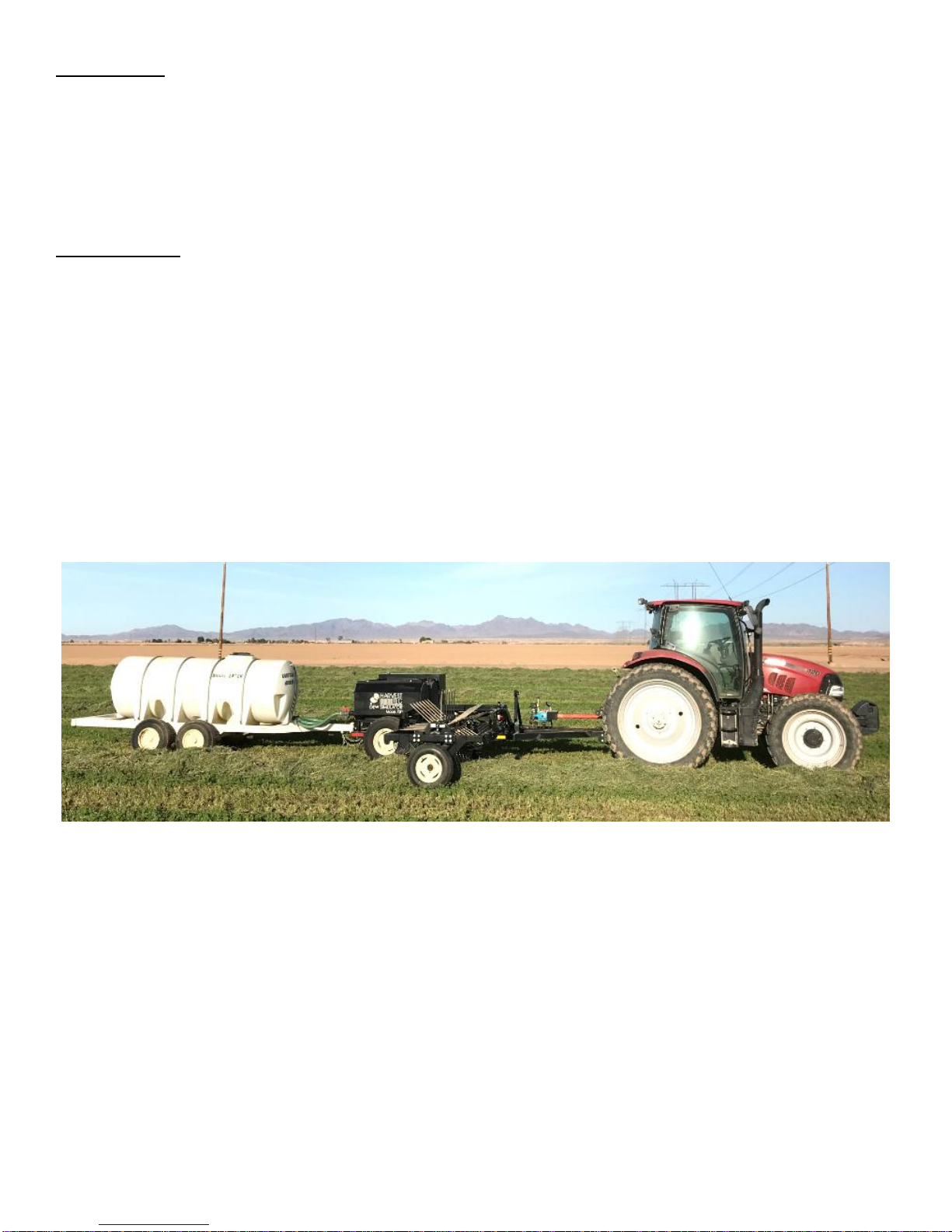
Suggested trailer and tank
o Tandem axle 1,000 gallon water trailer
Below is an example of a water tank, Dew Simulator and tractor setup.
5

Safety
DCL-720-03
DCL-720-06
DCL-720-04
DCL-720-05
DCL-720-07
DCL-720-08
DCL-720-09
DCL-720-10
DCL-720-11
DCL-Yellow Reflector
2” x 9”
DCL-Red Reflector
2” x 9”
Carefully read all the safety signs in this manual and on the equipment before use. Keep signs clean and in
clear view. Replace missing or damaged safety signs. Replacement signs are available from your local
authorized dealer. Keep your Dew Simulator in proper working condition. Unauthorized modifications to the
system may impair the function and/or safety of the machine. Carefully read and understand all of the safety
signs before installing or servicing the 720 Dew Simulator.
Safety Decal Definitions
6
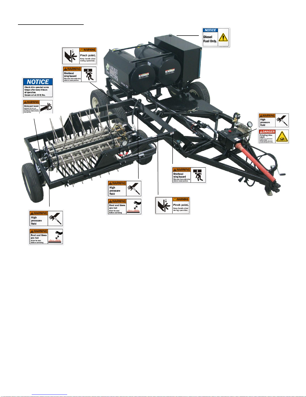
Safety Decal Locations
7
Setup
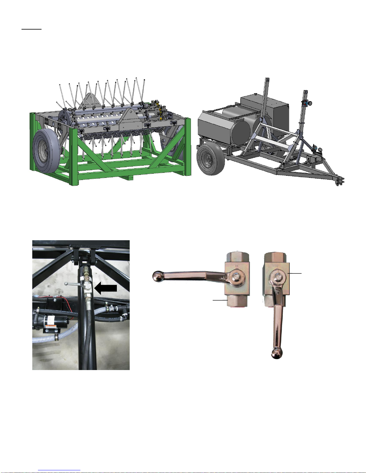
Reel Skid Assembly
Cart Assembly
Open
Closed
Unloading the machine
1. Unload the reel skid assembly and the cart assembly shown below and remove packaging. The reel skid is
designed to be handled from the front side (valves to right side) with pallet forks.
2. Attach the cart assembly to a tractor and connect the hydraulic couplers
3. Turn the hydraulic valve to the unlocked position
8
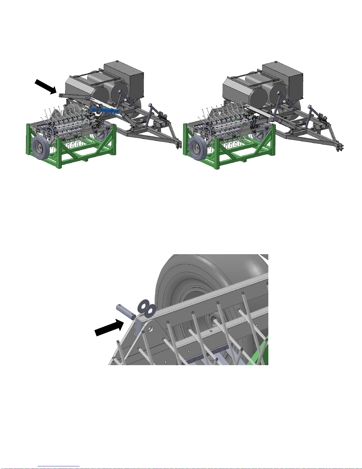
Connecting the Reel
Reel & Cart assemblies w/ lift arm being lowered
Reel & Cart assembly aligned
1. Position the reel skid assembly next to the cart assembly and lower the lift arm partial with the hydraulics
and position the reel so it is aligned, *side with valves goes towards the cart (below left).
2. Align the holes in the lift arms with the holes in the reel frame (above right).
3. Install the Pins & bushings (found in the cart parts box) see below. The bushings are located between the
inside of the reel frame brackets and the lift arm on the front and back side of the lift arm. After the pins and
bushings have been installed, cut the banding attaching the reel to the skid and lift the now connected reel
assembly into the full transport position so the lift arm is resting against the stops. Remove the reel
shipping skid.
9
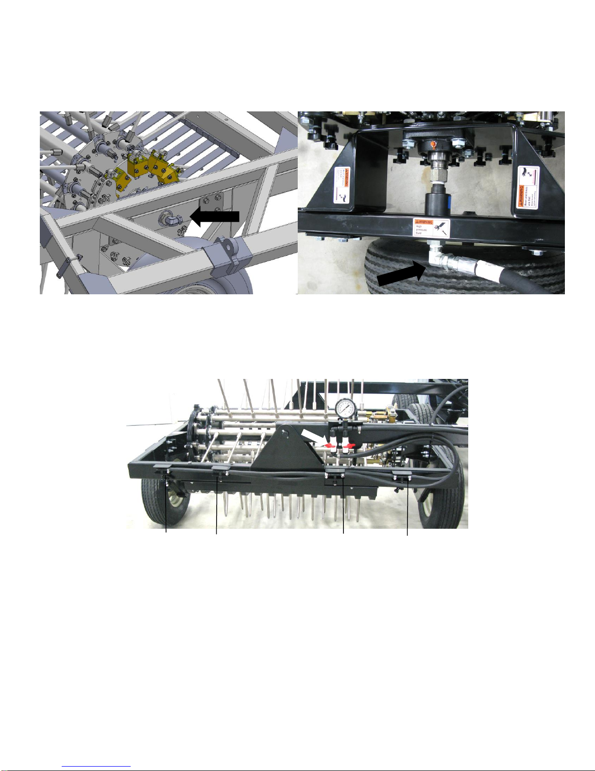
Connecting Hoses
Connection location on the reel assembly
Above view of the water line reel connection
Outside tip
Outside tip
Inside tip
Inside tip
Lower the reel from the transport position to the field operating position so both reel tires are on the ground.
Connect the stainless steel 3/4” water line attached to the back of the lift arm to the elbow attached to the
swivel (below). Secure hose to reel frame with supplied Jiffy clip.
Connecting the Perimeter Nozzle Hoses
1. Locate the gauge & valve manifold on the front of the lift arm attached to the reel assembly (below).
2. Following the routing path shown above connect the black 1/2” hose from the valve on the right to the
outside tip manifold straight fitting, cut to length and secure with hose clamp. On the opposite side of the
manifold route the hose to the other outside tip straight fitting on the left side of the reel assembly. The
hose and corresponding fitting are marked with color coded cable ties.
3. Following the routing path shown above connect the black 1/2” hose from the valve on the right to the
inside tip manifold straight fitting, cut to length and secure with hose clamp. The hose and corresponding
fitting are marked with color coded cable ties.
10
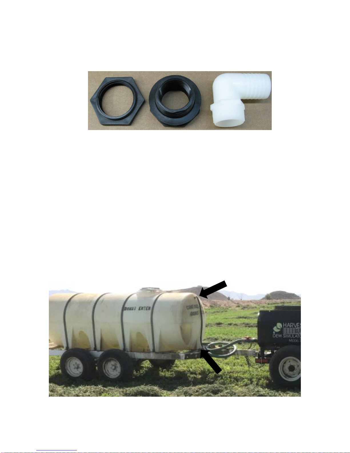
Preparing the Water Supply Trailer
The 720 Dew Simulator will require a water supply trailer (not included). The following step will explain the
installation of the supply, return fittings and hoses.
1. Install the 2” bulkhead (connector in the bottom of the tank. Then install the 2” elbow (003-EL2020) fitting in
the bulk head.
2. Attach the 2” hose (provided) to the 2” elbow fitting, route to front of trailer, cut hose to length and install 2”
valve/coupler.
3. Install 1/2” stainless steel bulkhead in bottom of the tank, or front side towards the bottom of tank, install
the steel 1/2” NPT x 3/4” Elbow (003-DSEL1234) and black green stripe hose. Route hose to rear of Dew
Simulator and cut hose to length, attach to the aluminum coupler (002-2204B). Locate the ¾” On/Off valve
with hose barb fittings attached between the coupler at the hitch and fitting at the bottom of the tank.
Secure the green stripe hose to each fitting and secure with the provided hose clamps. *Note that water
returning to the tank through this line will approach 200 F.
4. Install 3/4” plastic bulkhead on the front side of the tank near the top, or on the top side of the tank. Install
the 3/4” plastic elbow. Attach green stripe hose to the 3/4” plastic elbow and route hose to the rear of the
dew simulator. Cut hose to length and install the plastic male coupler. Secure the hoses with hose
clamps.
11
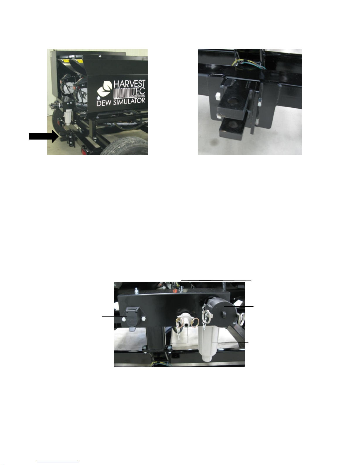
Hooking up Tractor, Dew Sim, and Trailer Tank
2” Valve Coupler
Trailer Light
Connection
3/4” Aluminum Coupler
3/4” Plastic Coupler
1. Connect the tractor to the cart assembly with a 1-1/4” draw pin (below).
2. Adjust the front hitch position to level the cart assembly to the tractor drawbar. The cleats can be moved up
or down as needed.
3. Connect the water trailer to the rear of the cart assembly with a 1-1/4” draw pin (shown above).
4. Adjust the rear hitch position to level the water trailer to the cart assembly
5. Connect the 2” valve/couple to the coupler at the rear of the Dew Simulator
6. Connect the metal valve assembly female coupler to the aluminum male coupler at the rear of the Dew
Simulator.
7. Connect the 3/4” plastic male coupler to the plastic female coupler at the rear of the Dew Simulator
8. Connect the trailer lighting connector to the rear of the Dew Simulator. See trailer wiring schematic for
additional information.
12
Machine Setup
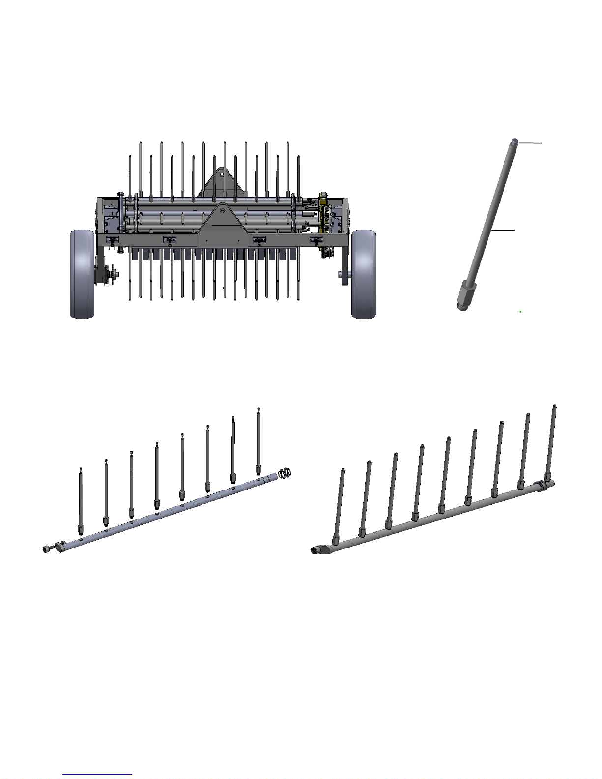
Reel Assembly
Tine / Tip Assembly
8-Tine Cross Tube Assembly (x5)
9-Tine Cross Tube Assembly (x5)
Tine
Tip
Installing Tines & Tips
The reel assembly is shipped with 65 tines installed each with a size MW11 tip (below left). There are 20 plugs
installed on the reel assembly as well that can be removed by using a 3/8” Allen wrench and replaced with
additional tines & tips (below right).
Tine Assemblies
Below are illustrations of the 8 and 9 Tine Cross Tube Assemblies located on the reel assembly. There are five
of each cross tube assemblies (below).
Each cross tube has two holes with a plug in the tube. If the width of the windrow is wider than 45.5” covered
by the initial 65 tine & tip assembles installed, adding additional tips will be necessary. Remove the plugs using
a 3/8” Allen and add in the new tine & tip assemblies. Each additional set of 10 tips will increase the width of
coverage by 6.5” with a maximum increase of 13”. Tighten to approximately 150ft/lbs, recommend that Teflon
tape or liquid thread sealant not be used, but that a drop of high strength locktite or equivalent be used on each
thread. Do not use Teflon tape or tocktite on the tips.
Tip and tine assemblies can also be removed and replaced with plugs to reduce the coverage for thin, light, or
narrow windrows.
13
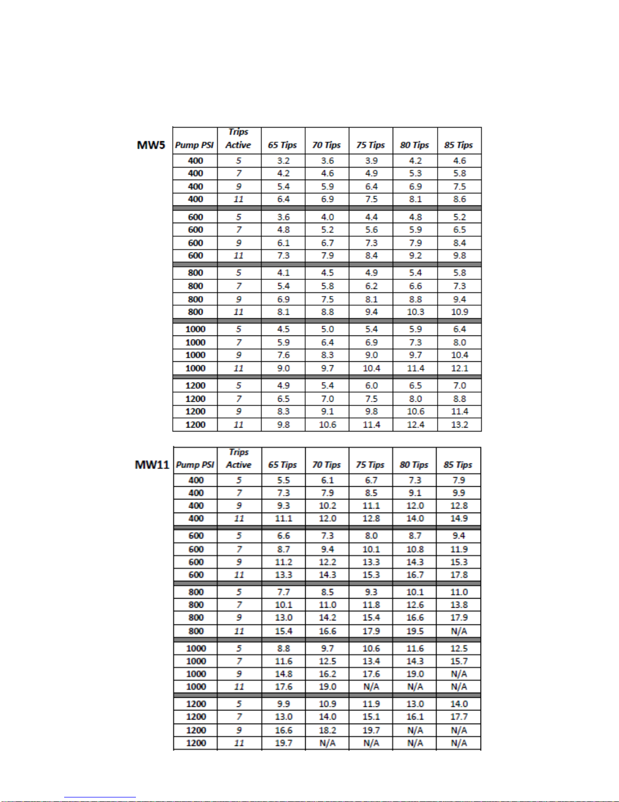
Tip Rate Chart
Use the chart below to determine the output (GPM) required by the dew simulator based on the field (ton/acre,
swath width, desired speed) and windrow (# of trips active) conditions. If tips need to be changed, a 7/16”
wrench or socket will be required to remove the tip currently installed. MW5 and MW11 tips, as well as
additional tines, can be purchased as spare parts from Harvest Tec.
14
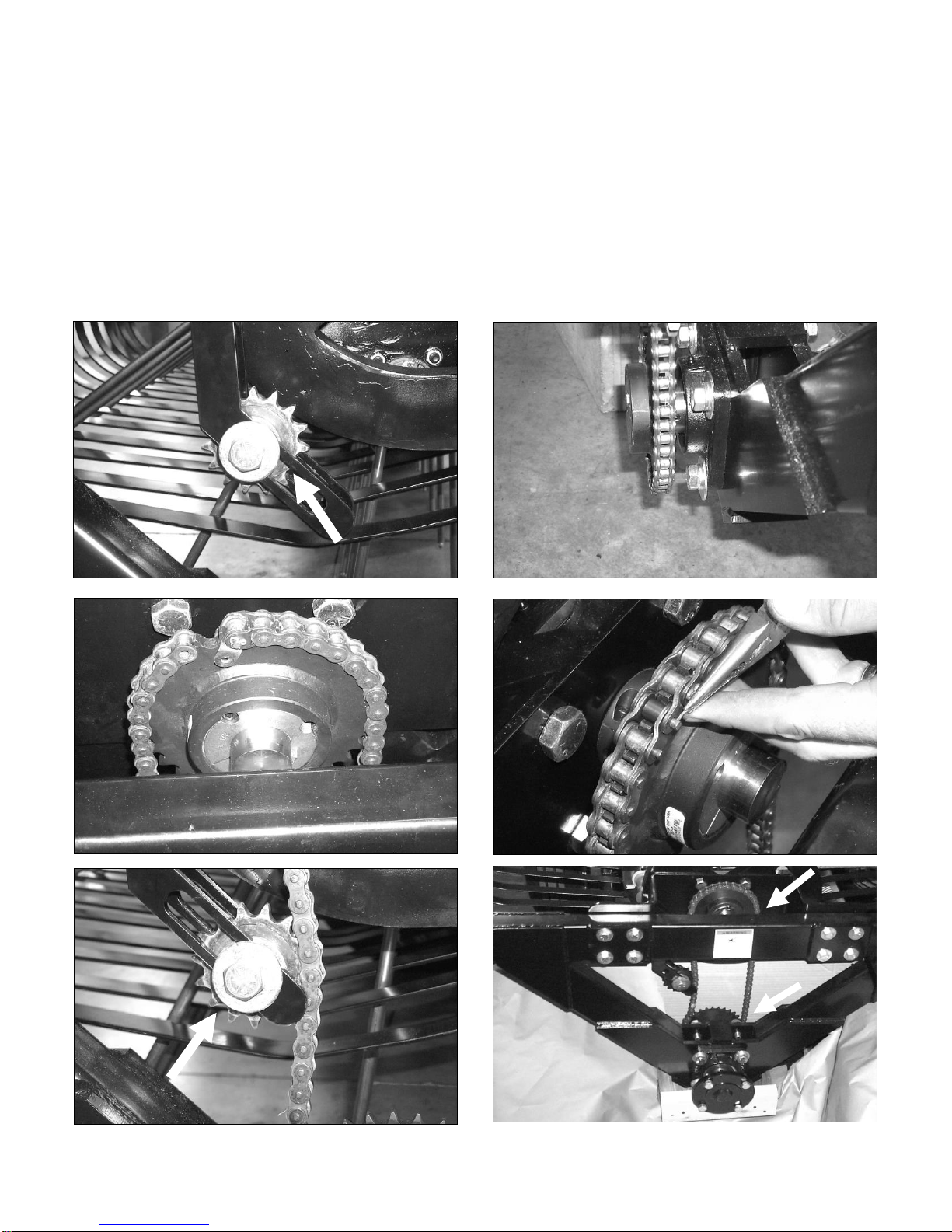
Drive Chain
1 2 3
4
5
6
The Model 720 Dew Simulator comes with a drive chain installed, which allows the reel to be ground driven at
a rate where rotation of the reel matched forward movement. This gearing allows the tines to enter and exit the
windrow without significant disturbance or movement of the windrowed material. In heavier windrows, or
windrows that have been raked tightly or raked multiple times, it is possible to run the machine without the
drive chain installed, letting the windrow turn the reel. This is recommended in most conditions.
In windrow conditions where the hay is either thin or the windrow is matted down and there is not enough
windrowed material to turn the reel, the drive chain will need to be installed. To reinstall the drive chain, begin
by loosening and sliding up the idler sprocket. Install the drive chain and complete the installation by moving
the idler down against the backside of the chain until it is tight and tighten the idler bolt.
15
Trip Sections
Trip active
Trip inactive
The trip sections shown (left) will determine when each cross
tube section will spray as the reel assembly rotates.
Adjusting Trip Sections
Adjust trip sections that are active based on windrow size/shape/and condition.
If the windrow is tall and fluffy, adjust the sections so the tines turn on as soon as they enter the
windrow.
If the windrow is shorter, shut off the leading trip sections so the tines do not turn on until they are about
to enter the hay.
If less water is required to be added to the windrow, turn off rear trip sections so the tines don’t spray
the entire time they’re in the windrow.
If there is moisture in the bottom of the windrow but the top 2/3 of the windrow is dry, turn off trip
sections at the bottom of the arc so the tines turn on as they enter the windrow and turn off for the
bottom 1/3, then turn back on until they exit the windrow.
To activate, loosen the adjustment bolt on the backside of the valve plate by loosening with a 3/8” wrench.
Slide the assembly up in the slot and retighten the bolt. To deactivate sections, loosen the bolt and slide down
in the slot away from the valves and tighten in position.
16

Adjusting Trip Sections (continued)
Front View Reel Trip Section
Reverse View Reel Trip Section
-Loosen and raise in slot, tighten to activate section
-Loosen and slide down in slot to deactivate section
Operation of Perimeter Nozzles
Adjustment
Bolts
On
Off
The perimeter nozzles are used to apply ambient temperature (non-heated) water in a course spray as a
supplement to the heated reel spray when evaporative conditions are high, either due to extremely low
humidity or the presence of wind. The perimeter nozzle spray is selectable, the spray can be focused on the
sides of the windrow, top of the windrow, or both, based on the valve settings on the perimeter nozzle
manifold. See picture below.
Left Valve – Inside Nozzles
Right Valve – Outside Nozzles
The perimeter nozzles operate off of a separate pump that is controlled by the switch and dial on the cab
controller. The toggle switch turns the pump on, and the dial is used to increase or decrease the pressure of
the tips. The chart below provides an estimate of the GPM for 2 and 4 tips at varying pressures. The perimeter
nozzle pump will automatically turn off when the Arm Switch is not activated and the Arm Override is not
activated.
17
Perimeter Nozzle GPM
PSI
XR11008VS
(x2)
XR11008VS
(x4)
10
0.80
1.60
15
0.98
1.96
20
1.13
2.26
25
1.26
2.53
30
1.39
2.77
35
1.50
2.99
40
1.60
3.20
45
1.70
3.39
50
1.79
3.58
Description of Electric Valves and Sensors
2Way Valve
The 2way valve is located on the pressurized side of the pump outlet at the rear
of the pump. When inactive, this valve is normally open. In its normally open
state, fluid from the outlet of the pump is returned to the tank. When it is closed,
fluid is forced through the front outlet manifold through the heaters and either
back to the tank or to the reel.
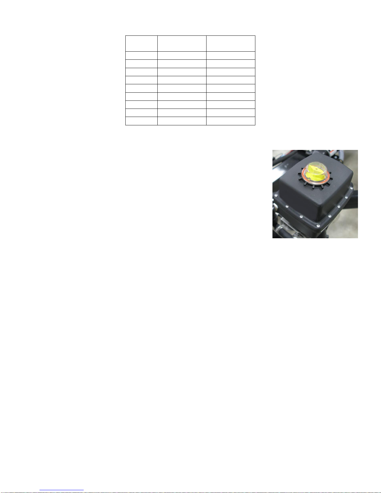
Warming Valve
The 2way warming valve is located towards the rear of the machine in between the heaters. The valve is on
the outlet side of heater #2 and is normally closed. When activated on the main screen of the control, it opens
and allows pressurized flow that has gone through the heaters to be returned to the supply tank. When the
heaters are activated and heating water, the warming valve, when opened, will allow heated water to be
bypassed back to the supply tank until the water temperature reaches 200F. Once the water temp reaches
200F, the warmup valve will automatically close and shut off on the main screen, forcing the heated
pressurized water out to the reel. The warmup valve is uses for initial priming (allowing bypass water back to
tank) and for initial heating of the system so water does not need to be sprayed on the ground until after the
temperature has reached 200F. The warmup valve will also automatically open to vent hot water back to the
tank if the output temperature rises above 270F and the flow stops. When this occurs, the green indicator light
for the warmup valve will illuminate to indicate that the valve is in the open position.
18

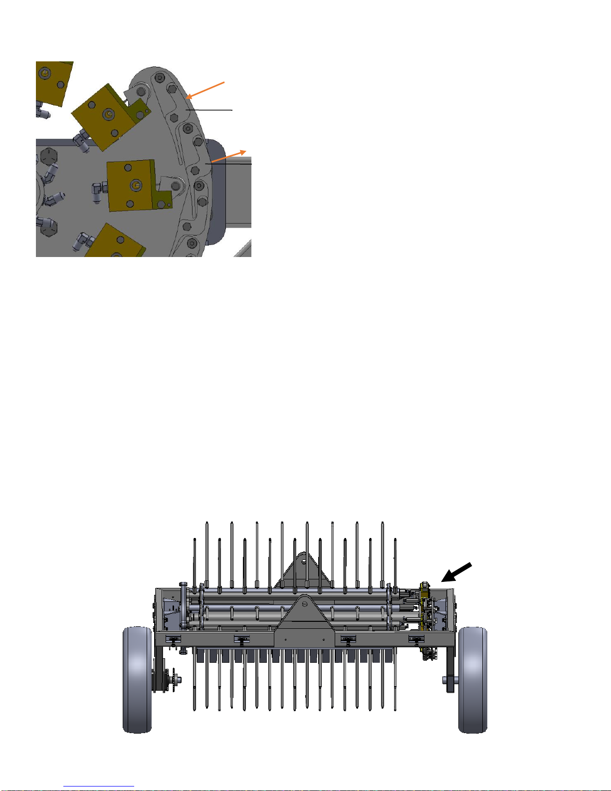
Arm Switch
Located towards the front of the machine on the right side of the lift arm (shown below). This is a mechanical
switch that senses when the reel lift arm is in the field operating position. The arm switch is active when it
senses the lift arm. The arm switch must be active for the 2way valve to close, thus directing flow out to the
heaters. When the arm switch is deactivated (normally open), flow from the pump is recirculated through the
pump.
For instance, if you are treating a windrow and raise the reel 12” off the ground, either when turning at the
headland or stopping in the windrow, the arm switch becoming deactivated will cause the 2way valve to open
and divert flow to the tank, shutting off flow to the reel. Similarly, for the heaters to run, the arm switch must be
active, so when the reel is raised the heaters will automatically turn off. Additionally, the system must also be
seeing a flow rate (GPM) from the flow meter before the heaters will run.
**For system priming and diagnostics, the arm switch can be overridden by the “ARM OVERRIDE” button on
the controller. Activating that button will cause the 2way valve to close and allow flow to go through the heaters
regardless of the lift arm position.
19
 Loading...