

Harvest TEC 300RB, 300RBC Installation Manual

Installation Manual
Model 300RB & 300RBC
Moisture Only Kit for Round Balers
300RB & 300RBC-16-INST
4/18
1

(intentionally blank)
2

300RB Installation Manual Table of Contents
Page
Introduction
4
System Requirements
4
Tools Needed
4
Bluetooth Receiver Lights
4
Installation of 300RB & 300RBC
5-16
Installation of Control - 300 RB
5
Installation of Control - 300RBC
6
Installation of Moisture Sensor Pads
7-16
Four Foot Wide Balers
7
Five Foot Wide Balers
8
John Deere 582
9
John Deere 854
10
John Deere Round Balers
11
Vermeer Balers
12
AGCO Baler Models
13-14
Rollbelt Baler – 300RBC
15-16
Installation of Bale Rate Sensor
16
Wiring Diagram – 300RB
17
Wiring Diagram – 300RBC
18
Pin Outs
19-20
Parts Breakdown
21-24
Control and Harnesses
21
End of Bale Sensor Kit
21
Moisture Pads
22
Optional iPad Mini Mounting Kit (030-2014MK)
23
Optional iPad Display Kit (030-4670DK)
24
Notes
25-26
Warranty
27
3
Introduction
Congratulations and thank you for purchasing a Harvest Tec Model 300RB or the 300RBC moisture only kit.
Please read this manual carefully to ensure correct steps are taken to attach the system to the baler. This
applicator is designed to read moisture through an Apple iPad. A parts break of the system is located in the
back of the manual.
Right and Left sides are determined by facing in the direction of forward travel.
System Requirements
*iPad Mini or iPad 3rd Generation (2012) or newer, running the current iOS operating system
or one version previous required for iPad option
Tools Needed:
- Standard wrench set
- Electric drill and bits
- Side cutter
- Standard nut driver set
- Standard socket set
- Hammer
- Center punch
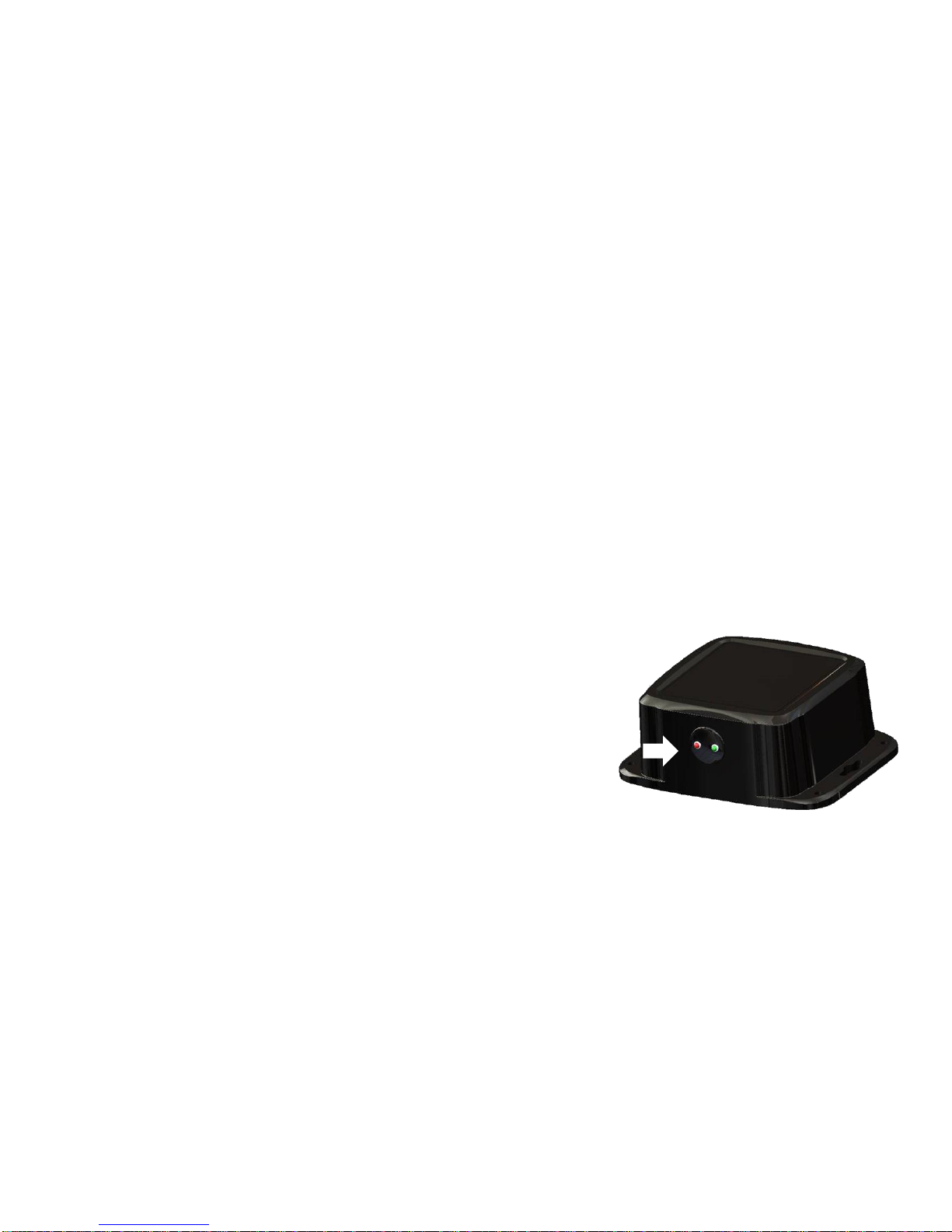
Bluetooth Receiver Lights
*New for production year 2018. All Bluetooth receivers (030-6672B) are
now equipped with lights to indicated both power and iPad connection.
Blinking Lights – System is waiting for the processor to connect, which
could take up to 35 seconds.
Red Light – The Bluetooth receiver has power
Green Light – When the proper active connection is selected in the Hay
App menu, the green light will indicate connection with the iPad.
4
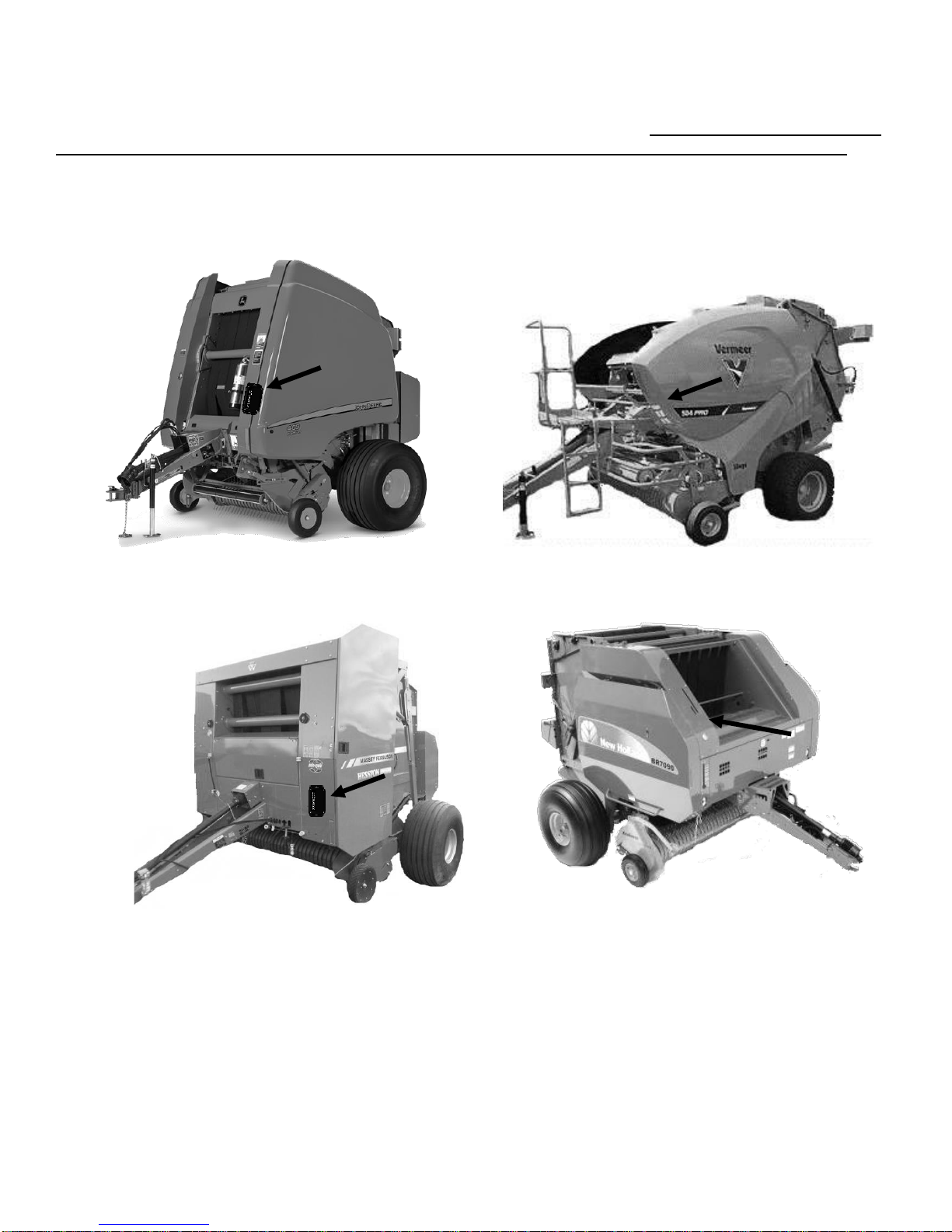
Installation of Control - 300RB
Mount THS on Front of Baler
Mount THS on Front of Baler
Mount THS on Front of Baler (under door)
Mount THS on Left Side of Bale Chamber Panel
Above Baler Shelf
Locate the controls package. Select a mounting location for the Three Hundred Series (THS) control box (0063671RB) easily accessible that is away from moving parts and access panels. Check before drilling to ensure
nothing will be damaged on the opposite side of the THS, some locations will be underneath baler doors. After
selecting the location for the THS, use the THS as a drill guide and mark the four mounting holes.
Drill the four mounting hole locations to 3/16" (5mm) in size. The locations shown below are examples of
mounting the THS on the baler. Use the supplied 10/32 x 3/4" Phillips flathead machine screws, nylock nuts to
mount the control box.
5
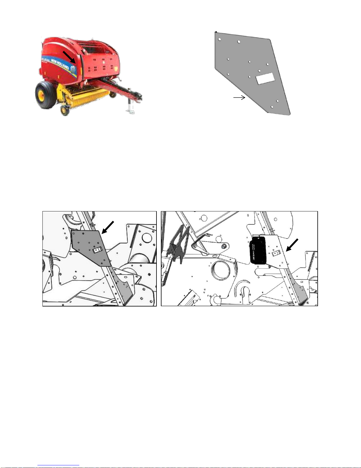
Installation of Control – 300RBC
001-4703XE
Figure 2
Mount THS on Front of Baler (under door)
Figure 3
Figure 1
1. Open right side door of baler.
2. Locate mounting holes for your size baler in bracket (001-4703XE). Mount bracket to pre-stamped square
holes on diagonal support structure of baler, (Figure 2). Secure with two M8 x 25mm carriage bolts and
flanged nuts.
3. Locate the controls package. Mount the 300RB control box to the 001-4703XE bracket as shown in figure
3. You may need to drill 3/16” holes on the plate to mount controller. Use the supplied 10/32 x 3/4" Phillips
flathead machine screws, nylock washers and nuts to mount the control box. (Figure 3).
6
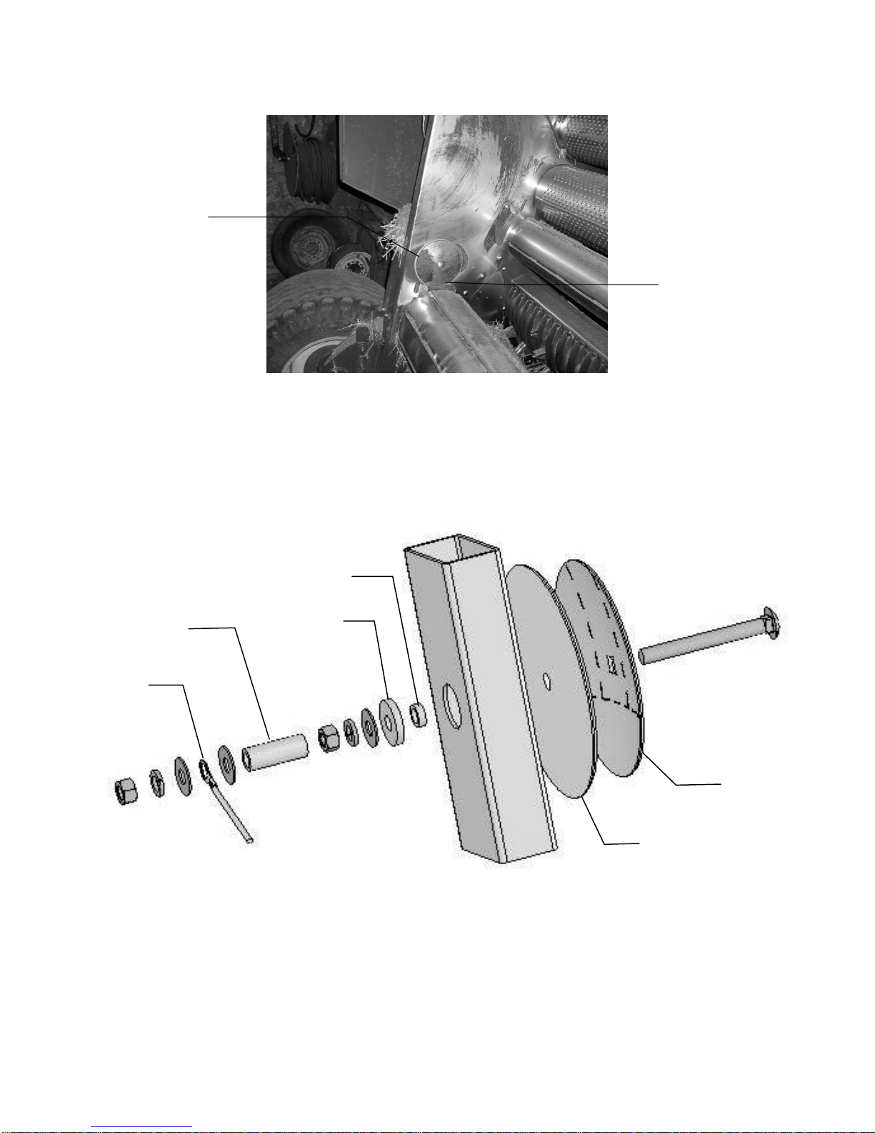
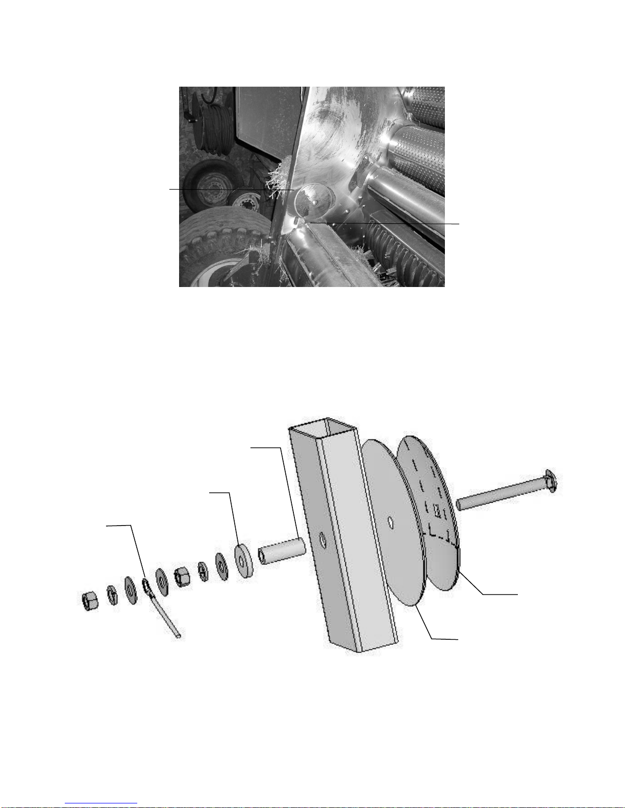
Installation of Moisture Sensing Pads
2” from back of
chamber (51mm)
1” from top of roll
(25mm)
Figure 1
006-4641G
006-4641G
006-4641I
006-4640G2
006-4641F
006-4641H
Four foot wide CNH balers (Pre 2015)
1. If your baler is equipped with bale shaping pads, remove disc and use existing hole that will need to be
drilled to 3/4” (19mm) to install new moisture sensing discs.
2. If your baler is not equipped with bale shaping pads you will need to drill a hole in the chamber directly
behind and above the starting roll (Figure 1).
3. The mounting hole will be 3/4" (19mm) in diameter. Use a plastic pad (006-4641F) and place it into the
baler to use as a template. The bottom edge of the pad will be placed 1” (25mm) up from starting roll and
2” (51mm) in from the back of the bale chamber. (Figure 1)
4. Locate the 006-4641G. The piece will need to be cut down to size. Use the already machined line in the
bushing to cut off the small piece shown above.
5. Depending on the baler the bolt may need to be trimmed for proper fit.
6. Tighten all of the hardware to 50 ft/lbs (68 N/m).
7. Make sure that the plastic pad is protecting all metal surfaces of the disc from touching baler.
8. Run the moisture wire harness (006-4640G2) from pump plate area to each disc and secure.
9. Apply silicone over nuts and washers.
7
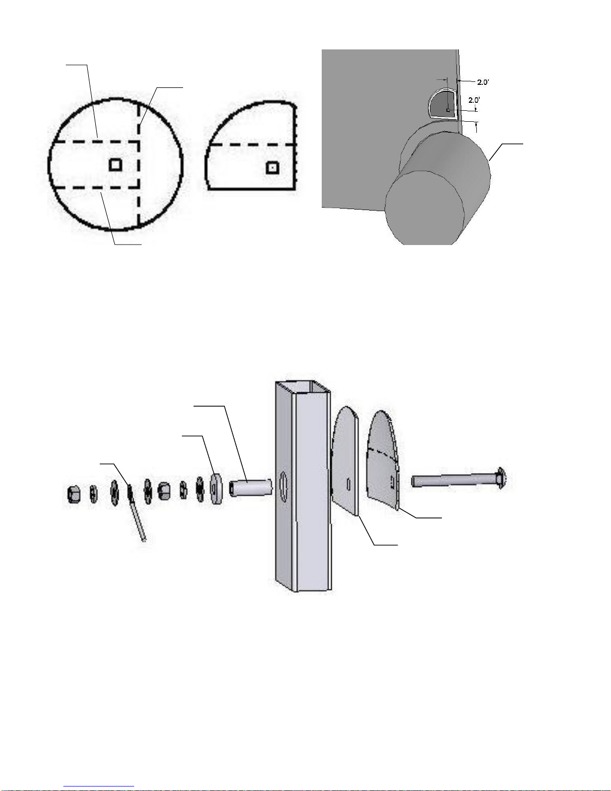
Installation of Moisture Sensing Pads (continued)
2” from back of chamber
(51mm)
1” from top of roll
(25mm)
Figure 1
006-4641G
006-4641I
006-4640G2
006-4641F
006-4641H
Five foot wide CNH balers (Pre 2015)
1. If your baler is equipped with bale shaping pads, remove disc and use existing that will need to be drilled to
3/4" (19mm) to install new moisture sensing discs. If the discs are welded, the welds will need to ground off
for disc removal.
2. If your baler is not equipped with bale shaping pads you will need to drill a hole in the chamber directly
behind and above the starting roll (Figure 1).
3. The mounting hole will be 3/4" (19mm) in diameter. Use a plastic pad (006-4641F) and place it into the
baler to use as a template. The bottom edge of the pad will be placed 1” (25mm) up from starting roll and
2” (51mm) from the back of the bale chamber. (Figure 1)
4. Depending on the baler the bolt may need to be trimmed for proper fit.
5. Tighten all of the hardware to 50 ft/lbs (68 N/m).
6. Make sure that the plastic pad is protecting all metal surfaces of the disc from touching baler.
7. Run the moisture wire harness (006-4640G2) from pump plate area to each disc and secure
8. Apply silicone over nuts and washers.
8
Install for John Deere 582
Figure 2
006-4640G2
006-4641I
006-4641G
006-4641F
006-4641H
A
B
C
Figure 1
1. The moisture discs (006-4641H) will both need to be cut on line A. (Figure 1) One disc will need to be cut
on line B and one disc on line C.
2. The plastic pad (006-4641F) will also need to be cut 1/4" longer than the back of the disc.
3. Bevel all sides of the cut discs to allow the smooth travel of crop over them.
4. The mounting hole will be 3/4" (19mm) in diameter. The disc will need to be placed on the baler lining up
the center of the bolt with the location 2” (51mm) up from bottom and 2” in from the back of the chamber.
(Figure 2)
5. Make sure that plastic pad is protecting all metal surfaces of disc from touching baler.
6. Run the moisture wire harness (006-4640G2) from the THS to each disc securing with cable ties.
7. On some balers the bolt may need to be trimmed for proper fit.
8. Tighten all hardware to 50 ft/lbs (68 N/m).
9. Apply silicone over nuts and washers.
9
 Loading...