

Harvestec 630 Operator's Manual

2003 1.321.219

.
INTRODUCTION
Dear Customer,
The following is some useful information provided to help ensure efficient and safe
operation of this corn head.
Read this manual carefully to learn how to operate and service your machine
correctly. Failure to do so could result in personal injury or equipment damage.
This manual should be considered a permanent part of your machine and should
remain with the machine when you sell it.
Since the corn head is universal type, carefully read your combine specifications and
follow the combine manufacturer's recommendations for usage, set-up and operation
of the combine.

TABLE OF CONTENTS
3
TABLE OF CONTENTS
SAFETY .................................................................................................................................... 4
IDENTIFICATION, TECHNICAL DATA ........................................................................... 10
1. Identification ..............................................................................................................................10
2. Technical data ............................................................................................................................11
SHIPPING CONDITIONS .................................................................................................... 12
MOUNTING THE CORN HEAD ON THE COMBINE ..................................................... 14
RUN-IN PROCEDURE ......................................................................................................... 21
SETUP PROCEDURE AND ADJUSTMENT OF THE CORN HEAD ............................. 22
HARVESTING ....................................................................................................................... 33
ROW SPACING ADJUSTMENT .......................................................................................... 36
MOUNTING TO ANOTHER TYPE OF COMBINE ........................................................... 39
MAINTENANCE AND LUBRICATION ............................................................................. 40
TROUBLE SHOOTING ........................................................................................................ 47
OFF-SEASON STORAGE OF YOUR CORN HEAD ......................................................... 48
WARRANTY, SERVICE, SPARE PARTS ORDER ............................................................. 48
LUBRICATION CHART ....................................................................................................... 49

4
SAFETY
This is the safety-alert symbol. When you see this symbol on your machine or in this
manual carefully read the message that follows, and be alert to the possibility of
personal injury or death.
Follow recommended precautions and safe operating procedures.
UNDERSTAND SIGNAL WORDS
SAFETY
A signal word – DANGER, WARNING, or CAUTION – is used with the safety-alert
symbol. DANGER identifies the most serious hazards.
DANGER or WARNING safety signs are located near specific hazards. General
precautions are listed on CAUTION safety signs. CAUTION also calls attention to
safety messages in this manual.
FOLLOW SAFETY INSTRUCTIONS
Carefully read all safety messages in this manual and on your machine safety signs.
Keep safety signs in good condition. Replace missing or damaged safety signs. Be sure
new components and repair parts include current safety signs.

SAFETY
5
GENERAL SAFETY GUIDELINES
1. ALLOW ONLY trained and experienced operators to operate your machine. Operating
this equipment safely requires the full attention of the operator. Do not wear
entertainment headphones while operating this machine.
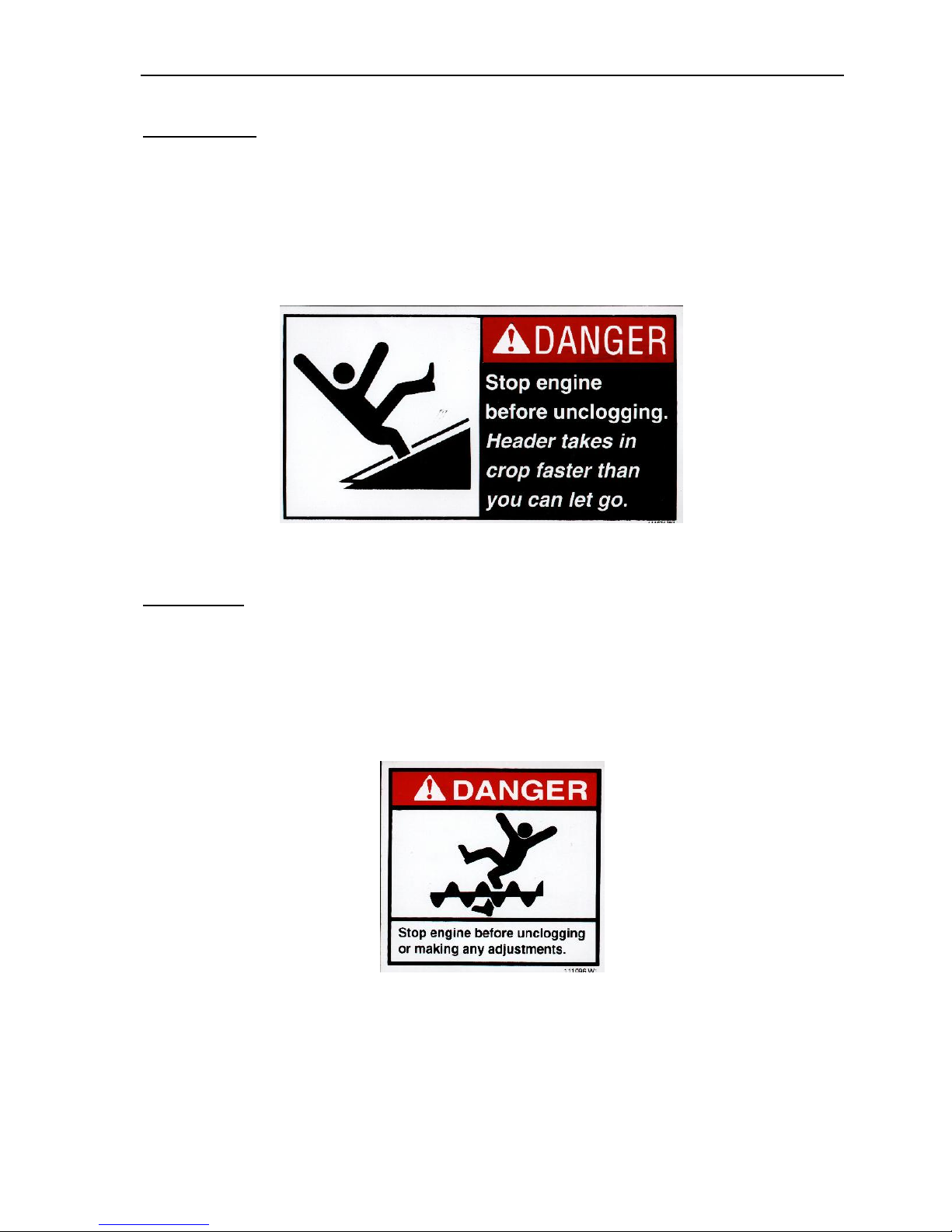
2. ALWAYS DISENGAGE header drive, shut off the engine and remove key before
servicing, adjustment, maintenance and lubrication to your corn head.
3. STAY CLEAR of the header when it is in operation.
4. DO NOT OPEN safety shields or covers while your corn head is running.
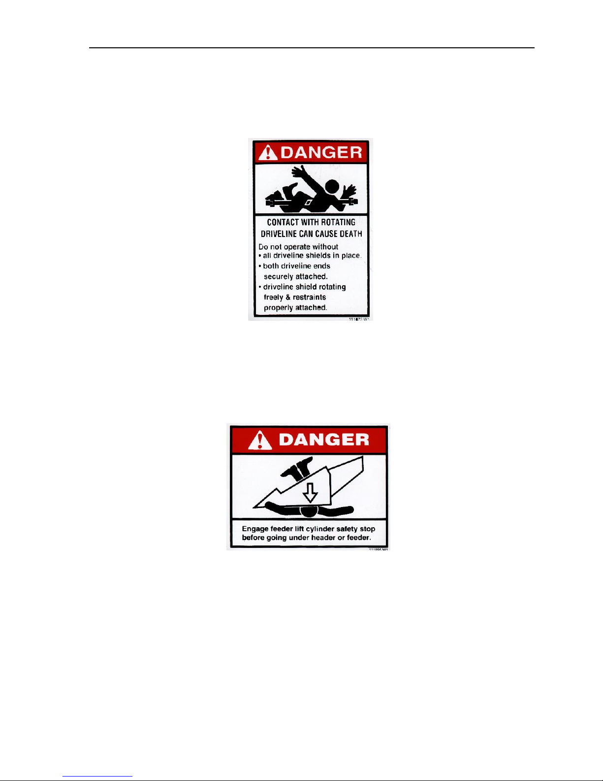
5. ENGAGE the lock on the feeder lift cylinder before doing any work under or around the
corn head.
6. CHOPPER KNIVES must not be installed without security locking pins.
7. WORN or DAMAGED CHOPPER KNIVES must be replaced before operation of the
corn head. Radial clearance between knife and bushing must be properly maintained. See
details in this manual.
8. It is FORBIDDEN to remove the warning lables from the machine. If they become
damaged or illegible they have to be ordered as shown in the Figures.
9. It is FORBIDDEN! to remove the safety hydraulic valve of the folding corn head located
on the upper support.
10. It is FORBIDDEN! to close or open the folding corn head when it is in operation.
6
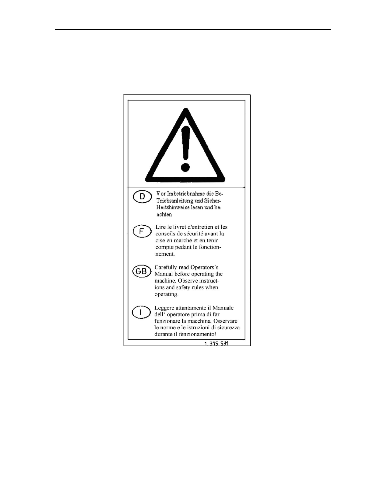
SAFETY DECAL
SAFETY
Carefully read Operator‟s Manual before handling the machine. When operating observe
safety instructions.
1.315.591
SAFETY
7
FRONT SIDE
Two reflecting strips are located at the ends on the front of the top beam facing forwards.
Fig A: Two decals are located on the front side of the header rear sheet (on each side of the
feeder opening).
FIG A
REAR SIDE
Two red reflector strips are located at the ends on the rear of the end shields facing rearward.
FIG B. Two decals are located on the rear side of the header back sheet (on each side of
the feeder opening).
FIG B
SAFETY
8
FIG. C: Two decals are located on the rear of the end shields.
NOTE: Four-row Corn Head will have one or two decals depending on the quantity of drive
shafts.
FIG C
FIG D: Two decals are located at the ends on the rear side of the header back panel above the
drive shafts.
FIG D
SAFETY
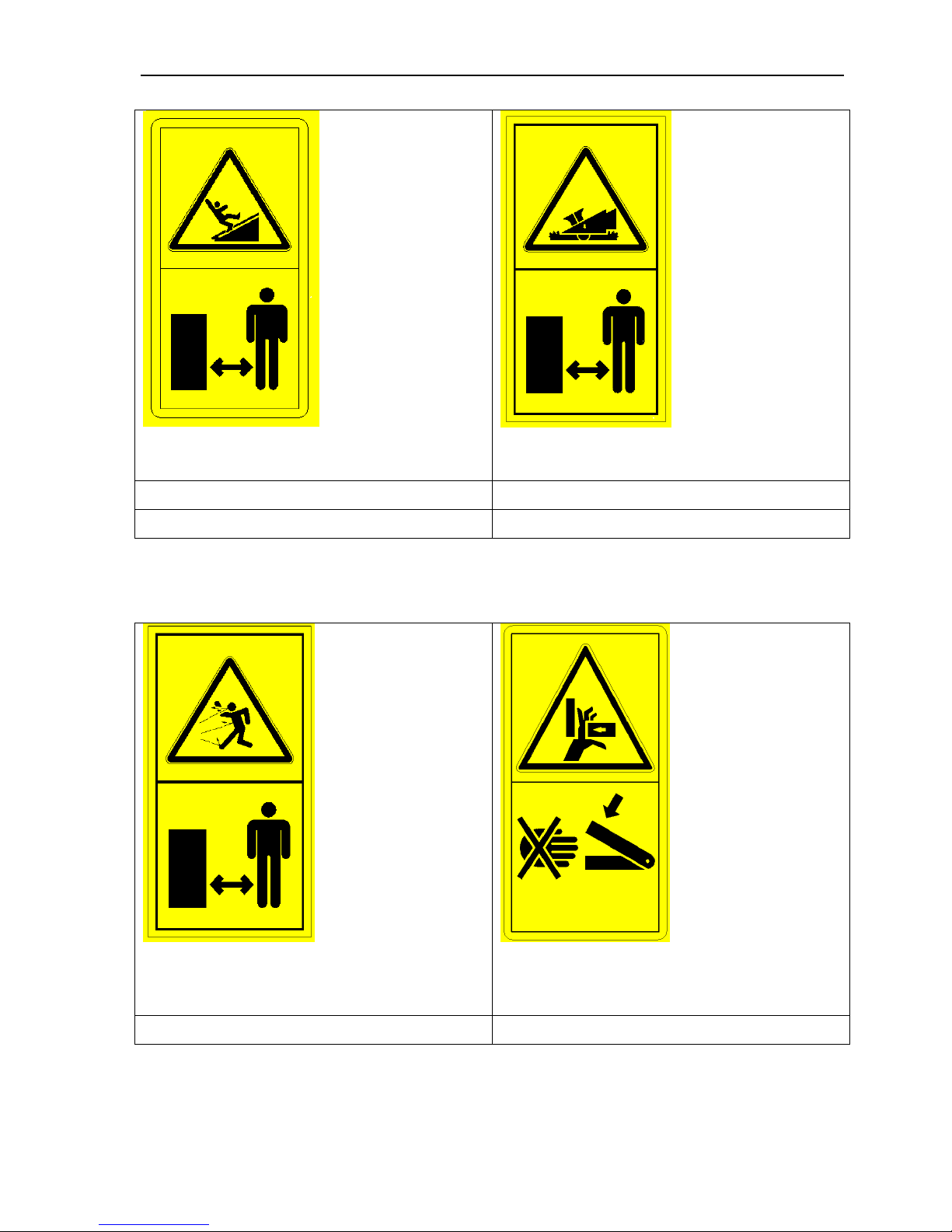
9
1.315.438 2 Decals
1.315.439 2 Decals
1.315.440 2 Decals
1.315.590 2 Decals
IDENTIFICATION, TECHNICAL DATA
10
IDENTIFICATION, TECHNICAL DATA
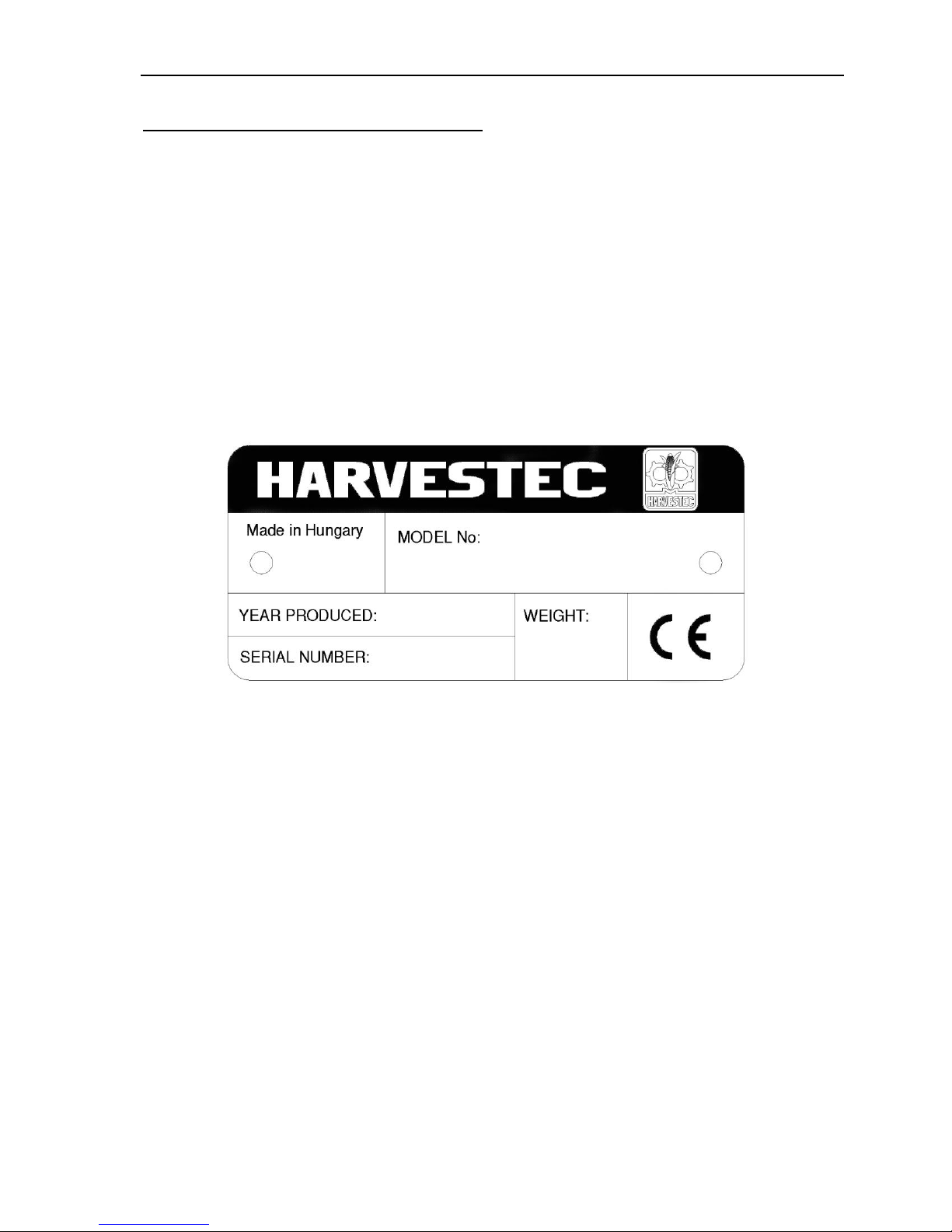
1. Identification
The corn head mounting is universal, so it can be assembled on specific combine types with
the appropriate mounting kit. A mounting kit is assembled to the corn head at the factory
when a machine is ordered. A data plate is provided located on the left side of the machine's
upper support.
The model number refers to the following: for example: HARVESTEC 630
Universal corn head
630 6-row fix frame corn head with 30” row spacing
HSA provided with stalk shredder located under the snapping roll

IDENTIFICATION, TECHNICAL DATA
11
Width(mm)
Length(mm)
Height(mm)
6-row 28-32"
4720
2950
1100
6-row 36-40"
5720
2950
1100
8-row 28-32"
6320
2950
1100
8-row 36-40"
7720
2950
1100
Width(mm)
Length(mm)
Height(mm)
6-row 28-32"
4720
950
2170
6-row 36-40"
5720
950
2170
8-row 28-32"
6320
950
2170
8-row 36-40"
7720
950
2170
Corn Head with
Steel
Snouts/Dividers
(less chopper)
Corn Head with
Plastic
Snouts/Dividers
(less chopper)
Corn Head with
Steel
Snouts/Dividers
(with chopper)
Corn Head with
Plastic
Snouts/Dividers
(with chopper)
4-row
1650 kg
1490 kg
1780 kg
1620 kg
6-row
2000 kg
1775 kg
2195 kg
1970 kg
8-row
2650 kg
2360 kg
2910 kg
2620 kg
6-row folding
2250 kg
2025 kg
2445 kg
2220 kg
8-row folding
3205 kg
2915 kg
3465 kg
3180 kg
2. Technical data
2.1. Dimensions (in operating condition)
2.2. Dimensions (in shipping condition)
2.3. Weight:
2.4. Lubrication specification: SAE 90 standard lubricating grease.
2.5. Pitch of the gathering auger is 450 mm.
2.6. Input shaft speed of the snapping unit drive: 550-620 rpm
2.7. Length of chopped stalk:
HSA = average 70 mm, depending on crop conditions.
2.8. Adjustment of the snapping plate is centrally electrical in-cab control switch.
2.9. Adjustable for row spacing
28"-30"-32"-(70 cm-76.2 cm-80 cm)
36"-38"-40"-(90 cm- 96.2 cm-100 cm)
SHIPPING CONDITIONS
12
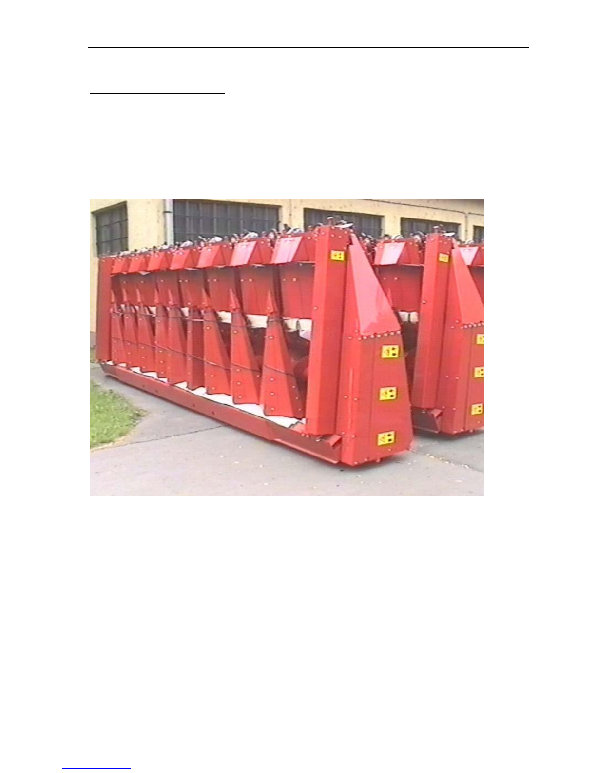
SHIPPING CONDITIONS
Your corn head is delivered with gearboxes filled with oil, and packaged on a shipping skid.
Oil levels should be checked before putting the Corn Head into operation.
SHIPPING CONDITIONS
13
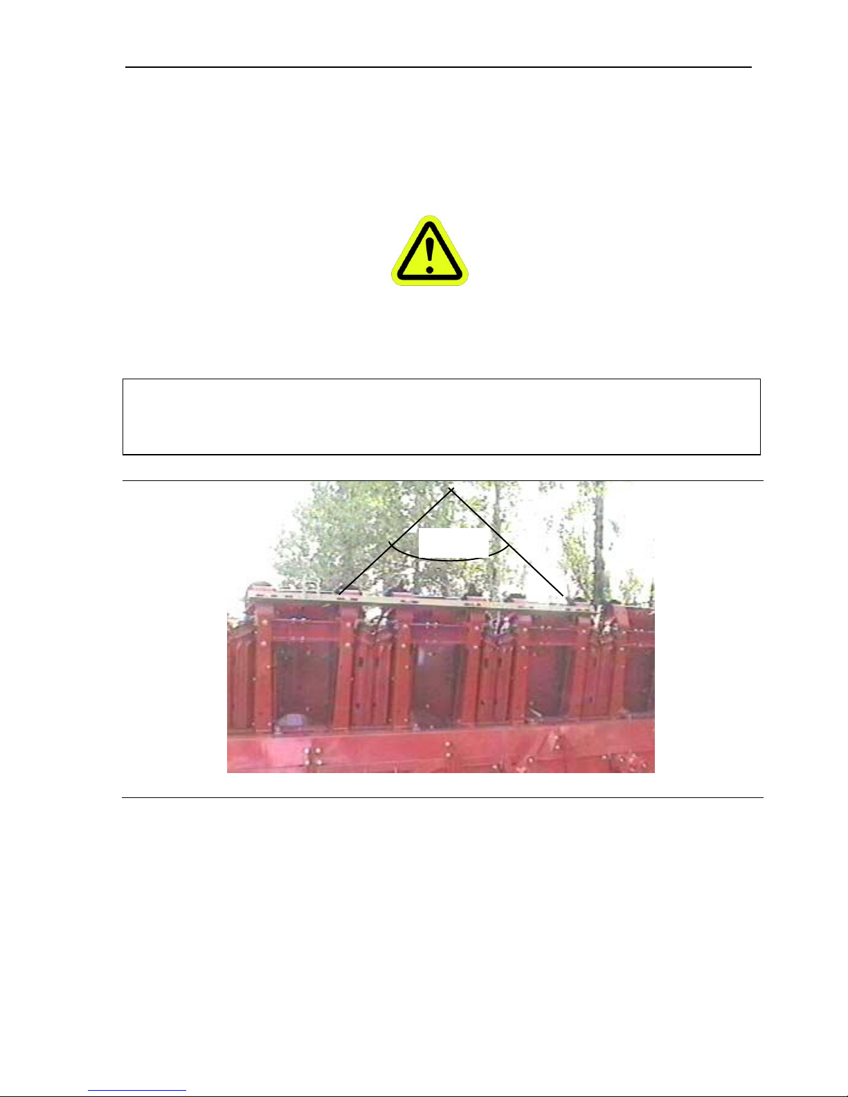
The corn head can be lifted with a suitable crane or forklift. When choosing lifting equipment
consider the weight as detailed in the Chapter 1, point 2.3. When lifting with a cable or chain,
the included angle should not exceed 90°.
Max 90°
The minimum cable length „L‟ to not exceed the max. 90° angle:
for 6-row fixed and folding frame and 8-row fixed frame is 1100 mm
The cable length should be equal on each side.
Use only a cable, which has capacity for the weight of the machine.
MOUNTING ON THE COMBINE
14
After the above operation and with the specified mounting kit securely attached to the Corn
Head, engage and securely attach the Corn Head to the combine according to Combine
Manufacturer‟s instructions and engage the feeder lift cylinder safety stop and secure the
lower latches.
MOUNTING THE CORN HEAD ON THE COMBINE
After removing the Corn Head from the shipping container, and while on shipping stand
Remove the parking stands and snouts from their stored shipping position
Install parking stands in their retracted (transport) position
Carefully lower the machine to horizontal position with a cable attached to lifting hooks.
Disassemble the transport skid after the machine is resting securely in horizontal position.
The corn head is shipped from the factory with mounting kit installed as ordered. If the corn
head will be mounted to a different combine than ordered for, remove the factory installed
mounting kit and install the required mounting kit as recommended for your combine.
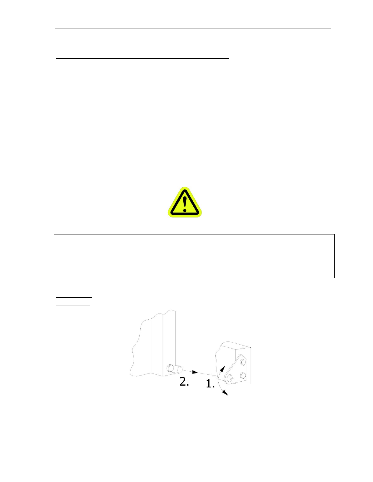
John Deere
9000 series
Insert the spring pivot pin of the feeder house into the hole of the secure plate, which is
assembled on the lower support. If it is required adjust the shaft alignment.
MOUNTING ON THE COMBINE
15
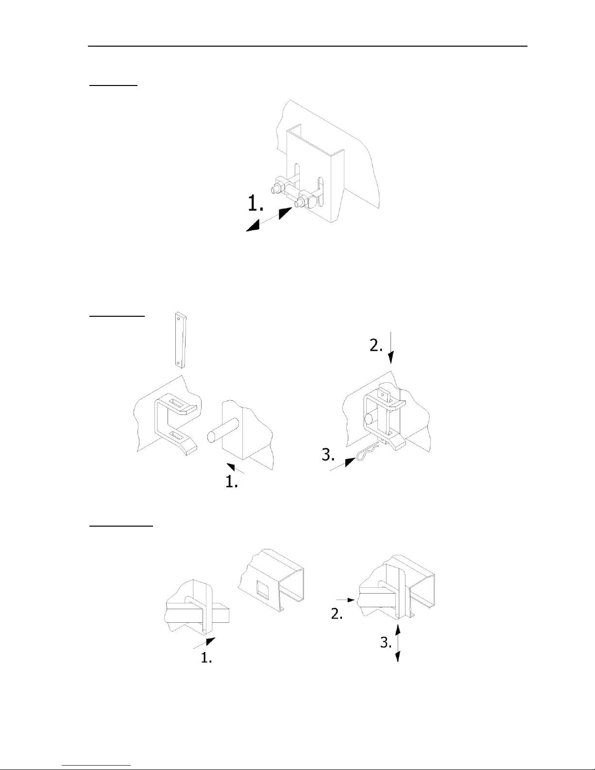
CASE IH
If necessary, adjust the nuts on the U-bolts to get the required force on the latches. Refer to
the combine Operator‟s Manual for the correct adjustments and latching methods.
Deutz-Fahr
Fiat-Laverda
 Loading...