

HARVEST H1364XT, H1374XT, H1384XT Assembly Manual
H1364XT,H1374XT,&H1384XTAUGERASSEMBLY
MANUAL
Read&understandallinstructionspertainingtothisaugerpriortouse!
Revised8/31/2015

Safety Alert
atch for this ALERT Symbol. It identifies potential hazards to Personal SAFETY and
W
your HEALTH. It points out Safety precautions.
This SAFETY symbol means:
ATTENTION:
BE ALERT
Why is SAFETY important to you?
THREE BIG REASONS:
*ACCIDENTS DISABLE AND KILL
*ACCIDENTS COST
*ACCIDENTS CAN BE AVOI
Failure to read this
equipment and a needless risk to your HEALTH and SAFETY. Your life and limbs are
worth keeping. Use this equipment with care.
Auger manual before operation of the Auger is a misuse of the
DED
Symbol
Signal Words:
DANGER, WARNING, CAUTION
The appropriate signal word for each message has been selected using the following
guidelines below the Alert Symbol.
BE ALERT!
D
A
N
G
E
N
U
N
U
R
R
R
T
G
G
T
T
R
E
R
E
R
– Indicates an imminently hazardous situation that, if not avoided, will result
N
I
N
G
N
I
N
G
N
I
N
G
– Indicates a potentially hazardous situation that, if not avoided, could result
O
O
O
–
N
N
N
Indicates a potentially hazardous situation that, if not avoided, may result
I
I
I
D
A
D
A
in death or serious injury. This signal word is to be limited to the most extreme situations,
typically for machine components that, for functional purposes, cannot be guarded.
W
A
W
A
W
A
in death or serious injury, and includes hazards that are exposed when guards are
removed. It may also be used to alert against unsafe practices.
C
A
U
C
A
C
A
in minor or moderate injury. It may also be used to alert against unsafe practices.
H13XTAssemblyManual Page2of33

TABLE OF CONTENTS
Tube Identification ……………………………………………….. 4
Step 1
Tube & Flighting Assembly ……………………………………………….. 5
Steps 2-5
Discharge Head Assembly ……………………………………………….. 6
Step 6
Cable Mount & Truss Assembly ……………………………………………….. 7
Steps 7 & 8
Infeed Housing Assemb
ly
……………………………………………….. 8
Steps 9-19
Transport Arm Assembly ……………………………………………….. 14
Steps 20 & 21
Truss Cable Assembly ……………………………………………….. 15
Steps 22-26
Hydraulic Hose Assembly ……………………………………………….. 19
Step 27
Carriage Assembly
(Identification) ……………………………………………….. 20
Step 28-43
Hydraulic Hose Assembly
(cont’d) ……………………………………………….. 29
Steps 44 & 45
Swing Tube & Hopper Assembly ……………………………………………….. 30
Steps 46-51
Parts Book Drawings
H13XTAssemblyManual Page3of33
………………………………………………..
34
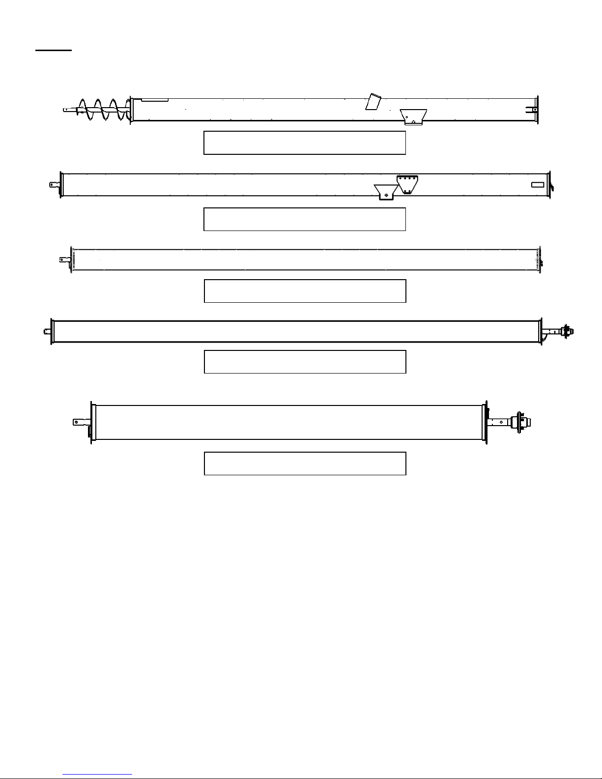
Step 1
Tube Identification
1st Tube H1364, H1374, & H1384XT
2nd Tube H1364, H1374, & H1384XT
3rd Tube, Discharge H1364XT
3rd Tube, H1374 & H1384XT
4th Tube, Discharge H1374XT
H13XTAssemblyManual Page4of33
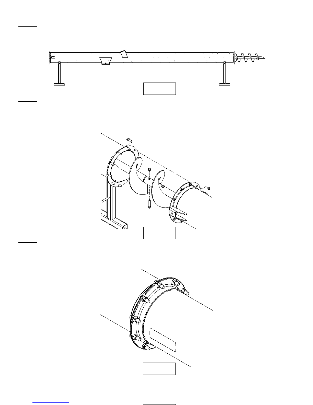
Step 2
Place tubes on assembly stands as shown. Place stands 12” or less from the end of the tube. Placing stands
further than 12” from end of the tube may cause damage to the tubes.
(Tube & Flighting Assembly)
Fig. 2.1
Step 3
Slide the flighting together from the 1st & 2nd tube. Connect the flighting using (3) 5/8" x 3” hex bolts and top
lock nuts. Align flighting as shown to make continuous. After connecting the flighting, slide the 1st & 2nd tube
together putting in (10) 1/2" x 1-1/2” flange bolts & nuts.
Step 4
Place the 3rd tube in front of the 2nd tube and connect the flighting & tubes as shown in Step 3. Connect the
flighting using (3) 5/8" x 3” hex bolts and top lock nuts. Connect the tubes using (10) 1/2" x 1-1/2” hex flange
bolts and flange nuts. If assembling an H1364XT please skip to Step 6.
Fig. 3.1
H13XTAssemblyManual Page5of33
Fig. 4.1
Step 5
Place the 4rd tube in front of the 3nd tube and connect the flighting as shown in Step 3. After the flighting is
connected and secure, slide the 3rd & 4th tube together as shown. Mount the cable attachment brackets (10680)
to the left and right side of the flange on the 3nd tube. Tighten the tubes and brackets together using (10)
1/2" x 1-1/2” flange bolts & nuts. After the bolts are tight, attached the 1/2” quick link to each bracket as
shown. Tighten both quick links.
(H1074XT & H1084XT Only)
Fig. 5.1
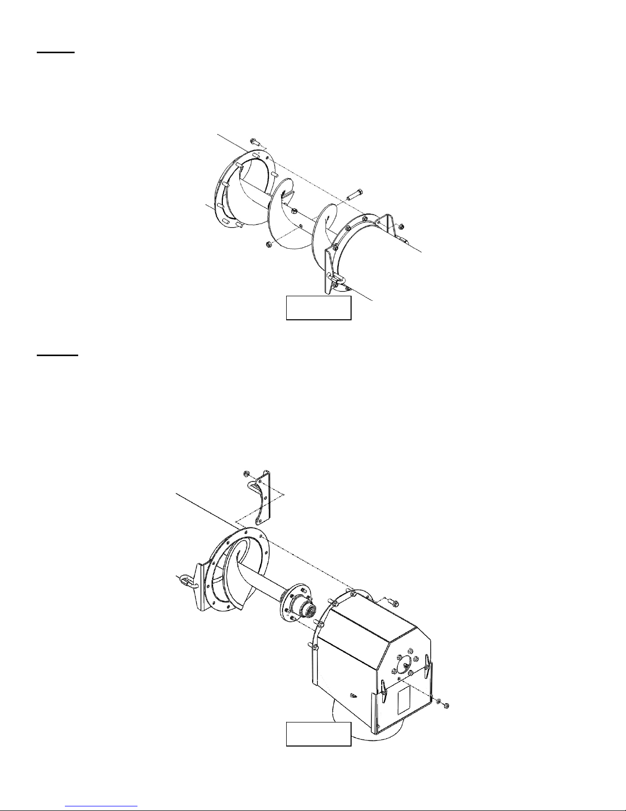
Step 6
All tubes & flighting should now be assembled together. Now the discharge head should be attached. First
align the 6 studs on the flighting with the 6 holes in the discharge head. Fasten the discharge head to the
flighting using (6) 1/2" lock washers & (6) 1/2" lug nuts. Thread lug nuts on flat side against the lock washers.
Tighten the 6 lug nuts. Next, fasten the discharge head to the tube using (10) 1/2" x 1-1/2” flange bolts & nuts.
Attach the cable attachment brackets (10680) & the 1/2” quick links will need to be mounted on both the left
and right side of the tube as shown in Step 5. Tighten all 10 bolts mounting the discharge head to the tube. Tie
red flag supplied in the kit to the discharge head.
(Discharge Head Assembly)
H13XTAssemblyManual Page6of33
Fig. 6.1
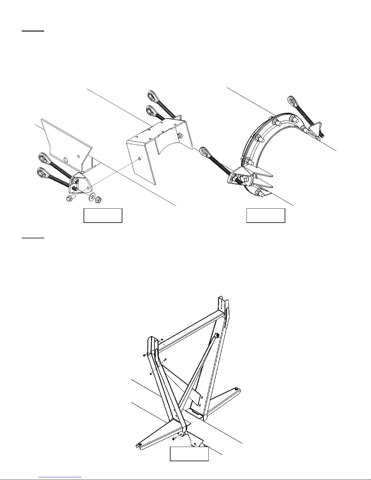
Step 7
(Cable Mount & Truss Assembly)
In Step 7 the lower cable mount brackets will be installed. On the 1st tube bolt cable mount brackets (31972) to
the left & right side of the hopper arm bracket as shown. These will be fastened using (2) 5/8” x 1-1/2” flange
bolts & nuts. Insert a 3/4" eyebolt into each hole of the cable mount bracket and attach each with 1 flat washer,
ext. tooth lock washer, & hex nut as shown in fig. 7.1. If assembling and H1374 or H1384XT attach the upper
st
cable mount brackets to the 1
tube as shown in fig. 7.2. Attach the brackets and eyebolts with the same
process as the lower cable winch mount brackets.
Step 8
Fig. 7.1
Fig. 7.2
Next the cable truss uprights assembled on the 2nd tube. Start by placing the 2 upright truss brackets (31971) &
2 of the side cable supports (13221) on the tube and fastening with a total of (12) 1/2” x 1-1/2” flange bolts &
flange nuts. Leave these a little loose for ease of assembling the cross member. Next, assemble the cross
member (13223) using a total of (4) 3/8” x 1” flange bolts & flange nuts as shown. Next, assemble the 2 “X”
braces as shown using (6) 3/8” x 1” flange bolts and nuts. Tighten all fasteners in this step. After all fasteners
are tigtened, place (2) 1/4” cable clamps on the side cable supports. Thread nuts on by hand but do not tighten.
H13XTAssemblyManual Page7of33
Fig. 8.1

Step 9
(Infeed Housing Assembly)
Loosen bolts and remove both side access panels. Remove 5 bolts and remove the top access panel. Using a
lifting strap, lift and slide the infeed housing over the bottom flighting on the 1st tube. Secure the infeed
housing to the first tube using (10) 1/2" x 1-1/2” flange bolts and nuts
Fig. 9.1 Fig. 9.2
H13XTAssemblyManual Page8of33
Fig. 9.3
Step 10
Next, slide the 4 bolt 1-3/4” cast flange bearing over the shaft making sure the grease zerk is located on the
same side as top bearing. (If the shaft has surface rust, clean first with an emry cloth) Secure the 4 bolt bearing
to the infeed housing using (4) 1/2" x 1-1/2” carriage bolts & flange nuts as shown. When completed use a
punch to rotate the shaft so the keyway is in an easy to access position.
Fig. 10.1
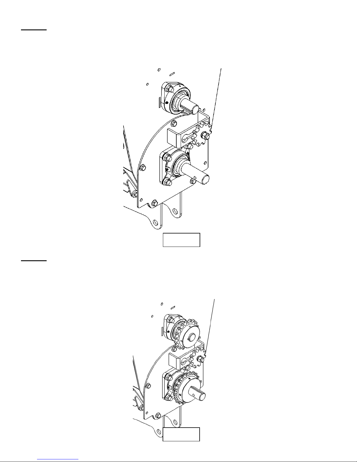
Step 11
Next, insert 1/4" x 1” square key into the top shaft & 3/8” x 1-1/2 “ key into the bottom shaft. Slide the 18 tooth
sprocket onto the top shaft & the 20 tooth sprocket onto the bottom shaft as shown in fig. 11.1. Use a
measuring tape & measure the distance from the center of each sprocket to the infeed housing. Once sprockets
are aligned, apply lock-tite to set screws & tighten.
H13XTAssemblyManual Page9of33
Fig. 11.1

Step 12
Locate the #60 chain, #60 half link, & #60 connector link. Attach the half link to the chain on one end & place
the chain around the sprockets as shown in fig. 12.1. Secure chain with connector link. When connector link is
installed & the loop has been completed, push the idler sprocket in the chain to achieve good tension. When
proper tension is achieved tighten the idler sprocket. Now grease top & bottom bearings with multi-lith grease.
Fig. 12.1
Step 13
Next, insert a 3/8" x 1-1/2” square key into the bottom shaft. Slide PTO shaft onto lower drive shaft. Align
holes in PTO shaft with hole in drive shaft. Using a punch will help in this application. Secure using a 3/8” x
3-1/2” hex bolt & top lock nut. Tighten set screw on PTO shaft.
H13XTAssemblyManual Page10of33
Fig. 13.1
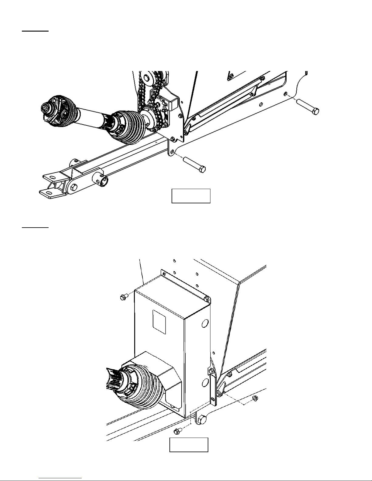
Step 14
Next, install the infeed tounge assembly to the infeed housing. Secure the tongue with a 3/4" x 6” hex bolt &
toplock nut through the rear of the infeed housing and the tounge tube. Next, lift the tongue up to the infeed
housing and insert a 3/4" x 6” hex bolt under the tounge in the from on the infeed housing. Secure the bolt and
tougue with a 3/4" toplock nut. Tighten all fasteners in this step.
Fig. 14.1
Step 15
Next slide the chain guard over the PTO shaft and secure to the infeed housing (2) 3/8” x 3/4" flange bolts &
flange nuts on the bottom and (2) 3/8” x ¾” flange bolts on the top. Then place lower “U” shaped guard place
onto guard and secure with (4) 3/8” x 3/4" flange bolts.
H13XTAssemblyManual Page11of33
Fig. 15.1
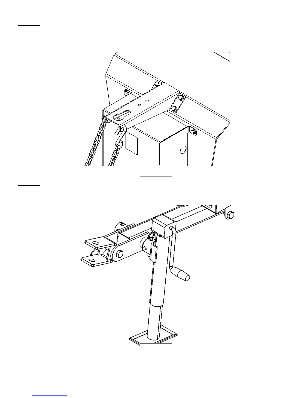
Step 16
Locate the PTO support bracket & mount it to the infeed housing as shown in fig. 16.1 using (4) 3/8” x 3/4"
flange bolts & flange nuts. Attach the PTO support chain to the bracket as shown using a 3/8” x 1” flange bolt
& flange nut.
Fig. 16.1
Step 17
Locate the jack and slide it onto the jack mount tube located on the side of the tongue. Secure jack with pin.
H13XTAssemblyManual Page12of33
Fig. 17.1
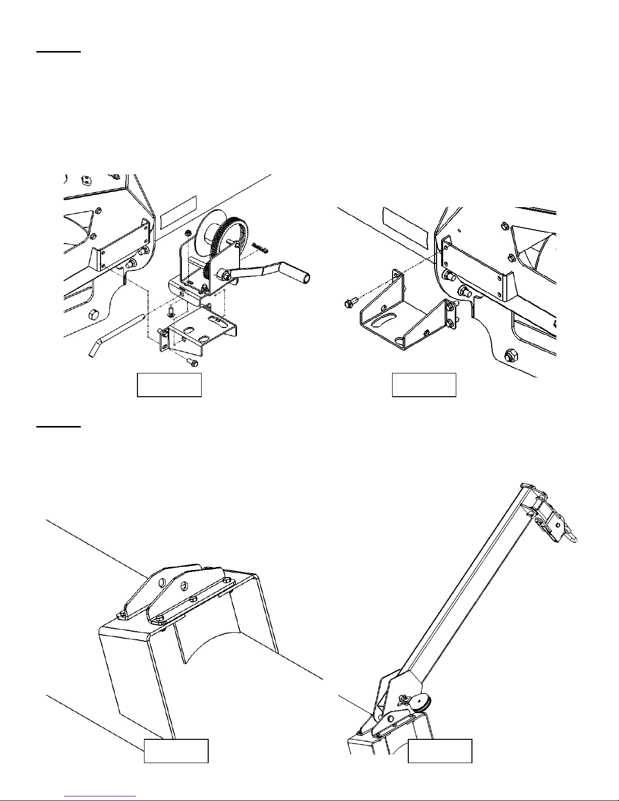
Step 18
Next the hopper winch will be mounted. On the right side of the infeed housing attache the winch mount
bracket (10131B) to the infeed housing using (4) 3/8” x 1” hex flange bolts & flange nuts. Next, mount the
winch retain bracket (10251) to the winch and secure with (3) 3/8” x 1” carriage bolts & flange nuts as shown in
fig. 18.1. Tighten bolts by hand only for now. Slide the winch handle onto winch with spring & nut. Tighten
nut to secure handle. Place winch on top of the mount bracket and secure with the 1/2” pin & hairpin. Angle
the winch so it is centered with the top bracket (hopper arm bracket) on the 1st tube. Tighten the (3) 3/8” x 1”
carriage bolts. Next, mount the other winch mount bracket on the left side of the infeed housing. Attach as
shown in fig. 18.2 with (4) 3/8” x 1” hex flange bolts & flange nuts.
Fig. 18.1 Fig. 18.2
Step 19 (Transport Arm Assembly)
After the left hand side winch mount bracket is secured, assemble the hopper transport arm to the 1st tube. This
will be done by attaching the arm mount brackets (10676) using (6) 3/8" x 1” hex flange bolts & nuts. Mount
arm on brackets using (1) clevis pin and 1/8” x 1-1/2” cotter pin as shown in figure 20.2.
Fig. 19.1 Fig. 19.2
H13XTAssemblyManual Page13of33
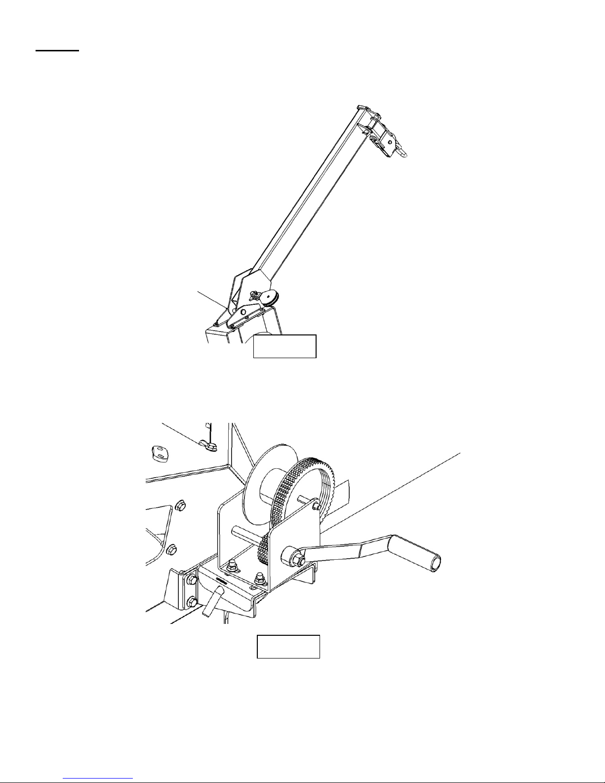
Step 20
Next the hopper lift cable will be assembled. Insert cable through the upper then the lower pulley on the hopper
transport arm. Pull cable back to the winch. Insert cable through hole on the side of the winch drum. Fasten to
winch using the winch cable clamp & nut profided with winch.
Fig. 20.1
H13XTAssemblyManual Page14of33
Fig. 20.2
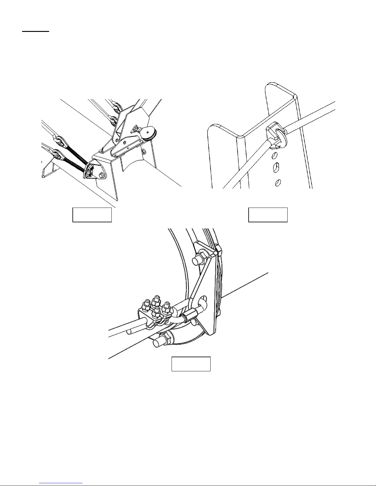
Step 21
(Truss Cable Assembly)
Take 1 long 1/2” cable & attach it to the upper eyebolt located in the middle of the first tube. Secure using (2)
1/2” cable clamps Pull cable to first truss and through a 1/2” cable clamp on the top of the truss. When the
cable is through the cable clamp, continue pulling the cable to the quicklink located on the discharge end of the
last tube. Secure using (2) 3/8” cable clamps as shown if figure 21.3. Repeat on opposite side of the auger.
Always have saddles of the cable clamps on the “live” end of the cable.
Fig. 21.1 Fig. 21.2
Fig. 21.3
H13XTAssemblyManual Page15of33
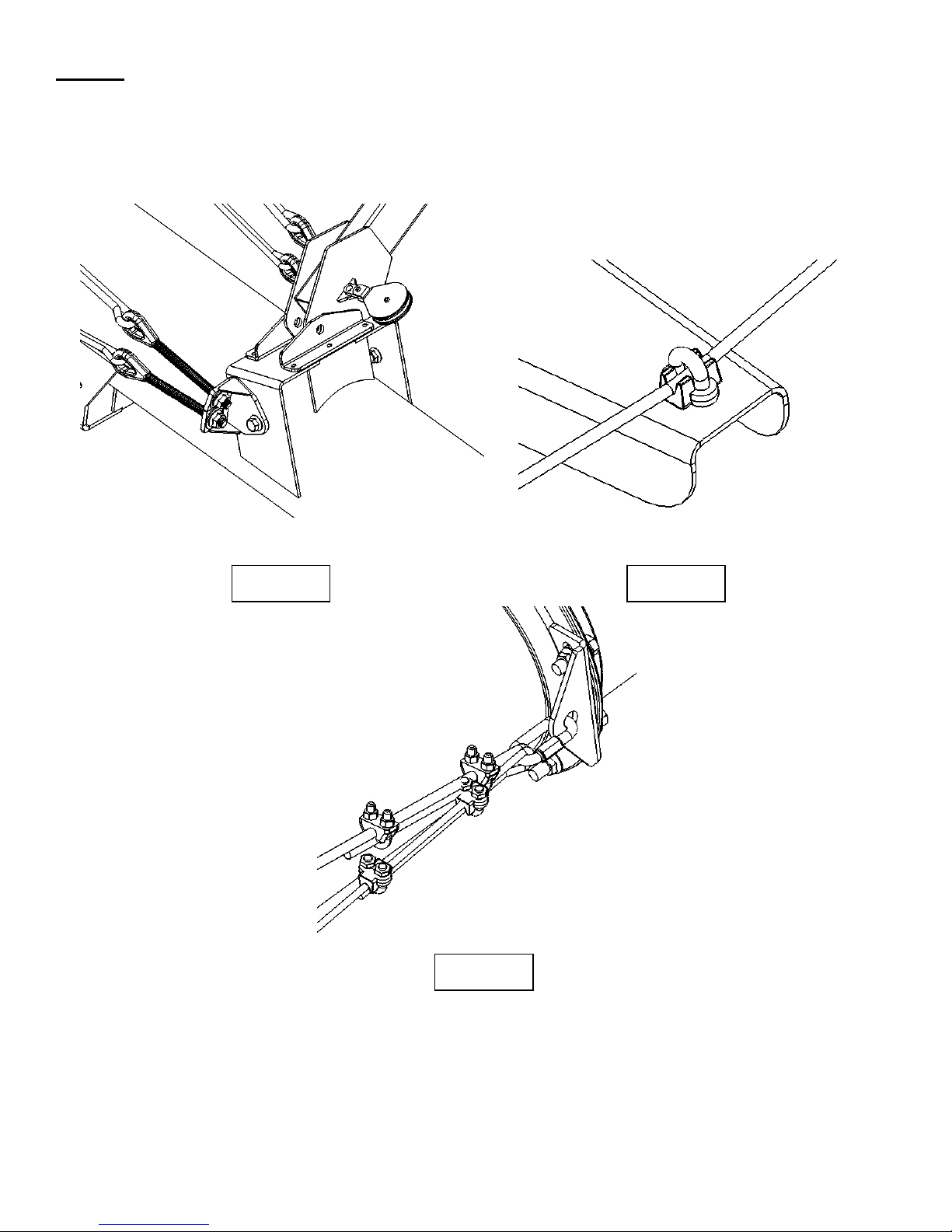
Step 22
Locate the 51 foot 3/8 cables. Attach it to the lower eyebolt located in the middle of the first tube. Attach using
the same process specified in step 21. Pull cable out to the side cable supports and through the 3/8" cable
clamp. When the cable is through the cable clamp, continue pulling the cable to the quick link located on the
joint on the end of the 3rd tube. (This will be on the same quick link for a H1364xt) Secure using (2) 3/8" cable
clamps. Repeat on opposite side of the auger. If assembling an H1364XT skip Step 24.
Fig. 22.1 Fig. 22.2
Fig. 22.3
H13XTAssemblyManual Page16of33
 Loading...