

Hartridge HK900 Operating Manual

HL030(EN), Issue 1, June 2005
World Leaders in Diesel Fuel Injection Test Equipment
HK900
All Makes Common Rail
Injector Test Kit (AVM2)
Operating Manual
THIS IS AN UNCONTROLLED DOCUMENT downloaded by Lukas Matuska on 16 Feb 2016
Any technical intervention requires certified Hartridge training. Contact Hartridge Ltd for details.

THIS IS AN UNCONTROLLED DOCUMENT downloaded by Lukas Matuska on 16 Feb 2016
Any technical intervention requires certified Hartridge training. Contact Hartridge Ltd for details.
HARTRIDGE LIMITED Operating Manual
HL030(EN), Issue 1, June 2005 1
CONTENTS
FOREWORD .........................................................................................................................................................3
1. INTRODUCTION .........................................................................................................................................7
1.1 SPECIFICATION ...............................................................................................................................................7
1.2 RELATED DOCUMENTS ...................................................................................................................................7
1.3 DEFINITION OF TERMS AND ABBREVIATIONS .................................................................................................7
2. INSTALLATION ..........................................................................................................................................9
2.1 FIXTURE INSTALLATION AND HYDRAULIC CONNECTIONS .............................................................................9
2.2 UPGRADE TO AE31 PUMP CONTROL UNIT ................................................................................................... 10
2.3 INJECTOR CONTROL UNIT ............................................................................................................................ 10
2.3.1 Fitting/Installation ............................................................................................................................... 10
2.4 ACCESSORY STORAGE.................................................................................................................................. 14
3. INTRODUCTION TO CR INJECTORS ................................................................................................. 15
3.1 CR INJECTOR OPERATION ............................................................................................................................ 15
3.2 INJECTOR VALVE TYPES .............................................................................................................................. 15
3.2.1 Solenoid Valves .................................................................................................................................... 15
3.2.2 Piezo Valves ......................................................................................................................................... 16
3.3 RECOMMENDED TEST SEQUENCE ................................................................................................................. 16
4. OPERATION .............................................................................................................................................. 17
4.1 GUIDELINES FOR SAFE WORKING PRACTICE ................................................................................................ 17
4.2 SOFTWARE OVERVIEW ................................................................................................................................. 17
4.3 TEST SETUP AND METHOD ........................................................................................................................... 19
4.3.1 Fit the Surrogate Pump ........................................................................................................................ 19
4.3.2 Load a Testplan .................................................................................................................................... 19
4.3.3 Measure Injector Coil Resistance ........................................................................................................ 20
4.3.4 Install Injectors in the Fixture .............................................................................................................. 20
4.3.5 Run the Test Steps ................................................................................................................................ 21
4.3.6 End of Test ........................................................................................................................................... 22
4.4 INTERPRETATION OF RESULTS ..................................................................................................................... 22
4.4.1 Response Time ...................................................................................................................................... 22
4.4.2 Delivery ................................................................................................................................................ 23
4.4.3 Backleakage (with HK901) .................................................................................................................. 23
4.4.4 Summary............................................................................................................................................... 23
4.5 CREATING/EDITING/SAVING TESTPLANS ..................................................................................................... 23
4.6 VIEWING AND PRINTING SAVED RESULTS.................................................................................................... 24
5. MAINTENANCE ........................................................................................................................................ 25
5.1 REGULAR MAINTENANCE ............................................................................................................................ 25
5.2 TROUBLESHOOTING ..................................................................................................................................... 25
5.2.1 Status Indicator Light ........................................................................................................................... 25
5.2.2 Other Faults ......................................................................................................................................... 25
6. SPARES ....................................................................................................................................................... 26
THIS IS AN UNCONTROLLED DOCUMENT downloaded by Lukas Matuska on 16 Feb 2016
Any technical intervention requires certified Hartridge training. Contact Hartridge Ltd for details.

Operating Manual HARTRIDGE LIMITED
2 HL030(EN), Issue 1, June 2005
This page left deliberately blank
THIS IS AN UNCONTROLLED DOCUMENT downloaded by Lukas Matuska on 16 Feb 2016
Any technical intervention requires certified Hartridge training. Contact Hartridge Ltd for details.

HARTRIDGE LIMITED Operating Manual
HL030(EN), Issue 1, June 2005 3
Foreword
Copyright
Hartridge Ltd. reserves the copyright of all information and illustrations in this publication which is
supplied in confidence and which may not be used for any other purpose other than that for which it
was originally supplied. The publication may not be reproduced in part or in whole without the consent
in writing of this company.
© Hartridge Ltd.
Safety Information
Warnings, Cautions and Notes
The precautionary notes in this publication, indicated by the words WARNING, CAUTION, or NOTE
provide information about potential hazards to personnel or equipment. Ignoring these notes may
lead to serious injury to personnel and/or damage to equipment. These notes appear as follows:
WARNING! INDICATES THAT A SITUATION MAY BE HAZARDOUS TO PERSONNEL.
INSTRUCTIONS ARE PROVIDED FOR AVOIDING PERSONAL INJURY.
CAUTION! Indicates that conditions exist that could result in damage to equipment.
Instructions are provided to prevent equipment damage.
NOTE Indicates additional information for clarification where there may be confusion.
Operational Warnings
WARNING! HIGH PRESSURE FLUID SPRAYS CAN CAUSE SERIOUS INJURY
OR DEATH.
COMMON RAIL SYSTEMS OPERATE AT EXTREMELY HIGH PRESSURES. IF
USED AS INSTRUCTED THE TEST KIT WILL RELIEVE ANY HIGH PRESSURE
WHENEVER THE GUARD DOORS ARE OPENED.
DO NOT ATTEMPT TO BYPASS THE PRESSURE DUMP VALVE OR THE
SAFETY INTERLOCK.
Safety glasses must be worn when working on this equipment for the following
reasons:
1. The test equipment is capable of producing high pressure fluid jets or sprays
which can cause severe eye injury in the event of a malfunction.
2. The test stand uses calibration fluid which is harmful to the eyes.
Always start the system running at a low pressure and visually check for any leaks
before setting higher pressures. This particularly applies having just mounted a
system, or having just replaced a component.
Do not open the guard while the system is running. Wait for the test bench drive to
stop and for the pressure to decay to a lower level before opening the guard.
THIS IS AN UNCONTROLLED DOCUMENT downloaded by Lukas Matuska on 16 Feb 2016
Any technical intervention requires certified Hartridge training. Contact Hartridge Ltd for details.
Operating Manual HARTRIDGE LIMITED
4 HL030(EN), Issue 1, June 2005
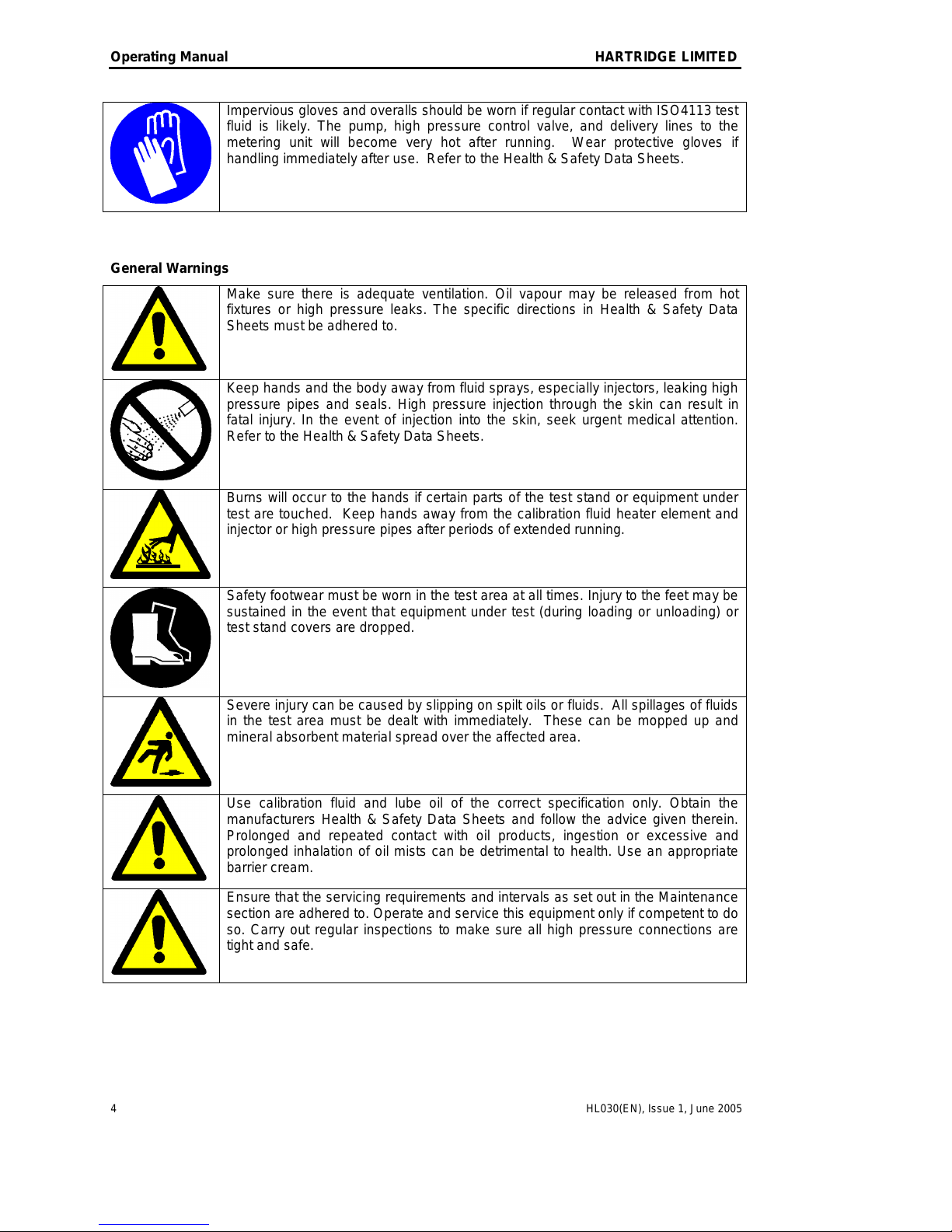
Impervious gloves and overalls should be worn if regular contact with ISO4113 test
fluid is likely. The pump, high pressure control valve, and delivery lines to the
metering unit will become very hot after running. Wear protective gloves if
handling immediately after use. Refer to the Health & Safety Data Sheets.
General Warnings
Make sure there is adequate ventilation. Oil vapour may be released from hot
fixtures or high pressure leaks. The specific directions in Health & Safety Data
Sheets must be adhered to.
Keep hands and the body away from fluid sprays, especially injectors, leaking high
pressure pipes and seals. High pressure injection through the skin can result in
fatal injury. In the event of injection into the skin, seek urgent medical attention.
Refer to the Health & Safety Data Sheets.
Burns will occur to the hands if certain parts of the test stand or equipment under
test are touched. Keep hands away from the calibration fluid heater element and
injector or high pressure pipes after periods of extended running.
Safety footwear must be worn in the test area at all times. Injury to the feet may be
sustained in the event that equipment under test (during loading or unloading) or
test stand covers are dropped.
Severe injury can be caused by slipping on spilt oils or fluids. All spillages of fluids
in the test area must be dealt with immediately. These can be mopped up and
mineral absorbent material spread over the affected area.
Use calibration fluid and lube oil of the correct specification only. Obtain the
manufacturers Health & Safety Data Sheets and follow the advice given therein.
Prolonged and repeated contact with oil products, ingestion or excessive and
prolonged inhalation of oil mists can be detrimental to health. Use an appropriate
barrier cream.
Ensure that the servicing requirements and intervals as set out in the Maintenance
section are adhered to. Operate and service this equipment only if competent to do
so. Carry out regular inspections to make sure all high pressure connections are
tight and safe.
THIS IS AN UNCONTROLLED DOCUMENT downloaded by Lukas Matuska on 16 Feb 2016
Any technical intervention requires certified Hartridge training. Contact Hartridge Ltd for details.
HARTRIDGE LIMITED Operating Manual
HL030(EN), Issue 1, June 2005 5
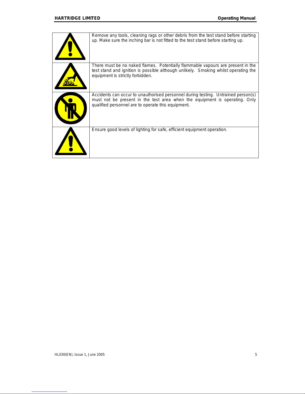
Remove any tools, cleaning rags or other debris from the test stand before starting
up. Make sure the inching bar is not fitted to the test stand before starting up.
There must be no naked flames. Potentially flammable vapours are present in the
test stand and ignition is possible although unlikely. Smoking whilst operating the
equipment is strictly forbidden.
Accidents can occur to unauthorised personnel during testing. Untrained person(s)
must not be present in the test area when the equipment is operating. Only
qualified personnel are to operate this equipment.
Ensure good levels of lighting for safe, efficient equipment operation.
THIS IS AN UNCONTROLLED DOCUMENT downloaded by Lukas Matuska on 16 Feb 2016
Any technical intervention requires certified Hartridge training. Contact Hartridge Ltd for details.

Operating Manual HARTRIDGE LIMITED
6 HL030(EN), Issue 1, June 2005
This page left deliberately blank
THIS IS AN UNCONTROLLED DOCUMENT downloaded by Lukas Matuska on 16 Feb 2016
Any technical intervention requires certified Hartridge training. Contact Hartridge Ltd for details.
HARTRIDGE LIMITED Operating Manual
HL030(EN), Issue 1, June 2005 7
1. Introduction
The HK900 Common Rail Injector Test Kit is designed to be fitted to the AVM2-PC Test Stand to
enable testing of Common Rail injectors. Additional mounting parts are available for testing specific
injector types.
NOTE: The AVM2-PC must be fitted with the following items in order to use the HK900 (all
available separately):
- HB378 Common Rail Base Kit
- HF1130 Common Rail Pump Test Kit
- Version 33 (or later) Magmah PC software
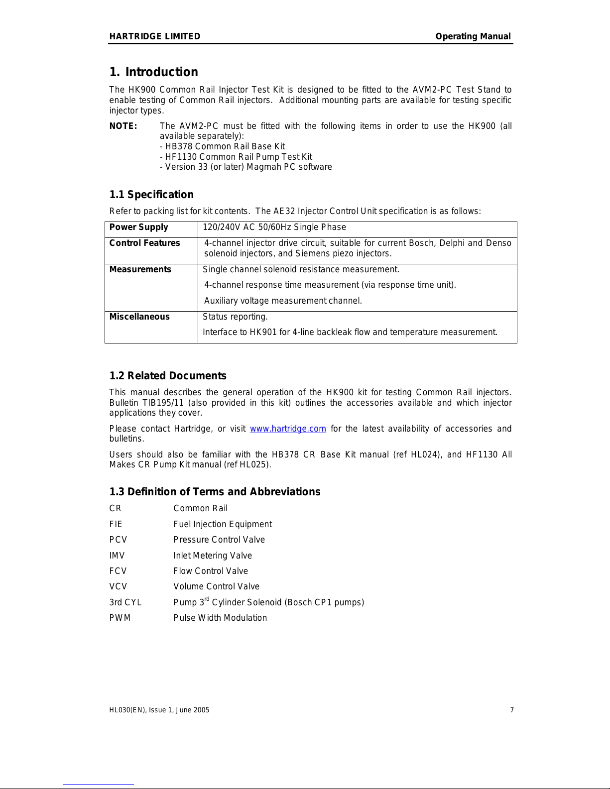
1.1 Specification
Refer to packing list for kit contents. The AE32 Injector Control Unit specification is as follows:
Power Supply
120/240V AC 50/60Hz Single Phase
Control Features
4-channel injector drive circuit, suitable for current Bosch, Delphi and Denso
solenoid injectors, and Siemens piezo injectors.
Measurements
Single channel solenoid resistance measurement.
4-channel response time measurement (via response time unit).
Auxiliary voltage measurement channel.
Miscellaneous
Status reporting.
Interface to HK901 for 4-line backleak flow and temperature measurement.
1.2 Related Documents
This manual describes the general operation of the HK900 kit for testing Common Rail injectors.
Bulletin TIB195/11 (also provided in this kit) outlines the accessories available and which injector
applications they cover.
Please contact Hartridge, or visit www.hartridge.com for the latest availability of accessories and
bulletins.
Users should also be familiar with the HB378 CR Base Kit manual (ref HL024), and HF1130 All
Makes CR Pump Kit manual (ref HL025).
1.3 Definition of Terms and Abbreviations
CR Common Rail
FIE Fuel Injection Equipment
PCV Pressure Control Valve
IMV Inlet Metering Valve
FCV Flow Control Valve
VCV Volume Control Valve
3rd CYL Pump 3rd Cylinder Solenoid (Bosch CP1 pumps)
PWM Pulse Width Modulation
THIS IS AN UNCONTROLLED DOCUMENT downloaded by Lukas Matuska on 16 Feb 2016
Any technical intervention requires certified Hartridge training. Contact Hartridge Ltd for details.
 Loading...