

Hart and Cooley TLC Installation Instructions Manual
Model TLC
PLEASE READ AND UNDERSTAND THE REQUIREMENTS BEFORE PROCEEDING
Installation Instructions
All-Fuel Chimney - 5” to 8”
Factory-Built Type HT Insulated Chimney - Tested to UL103
Type of Appliances
Your Model TLC chimney is intended for venting gas,
liquid, or solid fuel-fired, residential-type appliances and
building heating appliances or as defined in NFPA 211, in
which the maximum continuous flue gas temperatures do
not exceed 1000°F. It has been tested and approved to
withstand temperatures of up to 2100°F for three
10-minute intervals.
Pre-Installation Guidelines
If you choose to have your product installed by
others, we recommend these products be installed by
professionals who are certified by NFI (National Fireplace
Institute) or equivalent.
Your Model TLC chimney and connecting stovepipe
diameter should be sized in accordance with the
appliance manufacturer’s recommendations.
Plan the installation of your appliance and chimney in
such a way that both your chimney and your stovepipe
run as short and straight as possible. By having too long
and/or multiple-bend installations, you can reduce system
draft that can affect the operation and/or performance
of your appliance and/or chimney system. The chimney
should be located within the building in order to avoid
cutting or altering load-bearing members, such as joists,
rafters, studs, etc. If you have to cut or alter an existing
load-bearing member, special reframing methods are
required, which often include doubling of adjacent
members. If such a case arises, contact your local
Building Code Official regarding local regulations and
proper installation methods.
Sections of the Model TLC chimney that pass through
accessible areas of the building, such as through closets,
storage areas, occupied spaces, or any place where the
surface of the chimney could be contacted by persons
or combustible materials, must be enclosed in a chase
to avoid personal contact and damage to the chimney.
The chase may be fabricated using standard building
materials. Drywall mounted on 2” x 4” studs is typically
used in this situation. The space between the outer wall
of the chimney and the enclosure must be at least a
minimum of 2 inches.
MAINTAIN A 2-INCH MINIMUM AIRSPACE
CLEARANCE BETWEEN INSULATED CHIMNEY
SECTIONS AND COMBUSTIBLE MATERIALS.
WARNING: A MAJOR CAUSE OF CHIMNEY-RELATED
FIRES IS FAILURE TO MAINTAIN REQUIRED
CLEARANCES (AIRSPACES) TO COMBUSTIBLE
MATERIALS. IT IS OF UTMOST IMPORTANCE
THAT THIS CHIMNEY BE INSTALLED ONLY IN
ACCORDANCE WITH THESE INSTRUCTIONS.
Please read all instructions before beginning your installation.
Failure to install this system in accordance with these instructions will
void the conditions of certification and the manufacturer’s warranty.
Keep these instructions in a safe place for future reference.
Hart & Cooley, Inc.
1
Model TLC All-Fuel Chimney - 5” to 8” Installation Instructions
WARNING: DO NOT PLACE ANY INSULATING MATERIALS
OR RUN ANY ELECTRICAL WIRING WITHIN
THE REQUIRED AIR CLEARANCE SPACE
SURROUNDING THE CHIMNEY.
Before beginning the installation, ensure that you obtain
any necessary building permits, and that your installation
will conform with all federal and municipal building code
requirements.
CONTACT LOCAL BUILDING OR FIRE
OFFICIALS ABOUT RESTRICTIONS AND
INSTALLATION INSPECTION IN YOUR AREA.
The National Fire Protection Association Standard 211
states: Factory-built chimneys that pass through floors of
buildings requiring the protection of vertical opening shall
be enclosed with approved walls having a fire-resistance
rating of not less than one hour where such chimneys are
located in a building less than four stories in height, and
not less than two hours where such chimneys are located
in a building four or more stories in height.
WEAR SAFETY GLOVES WHEN HANDLING
SHEET METAL PARTS WITH SHARP EDGES.
The chimney must extend not less than 3 feet above
the highest point where it passes through the roof of a
building and not less than 2 feet above any portion of the
building within 10 feet (Figure 1). See Chart 2 - Chimney
Height Above the Roof on page 17 of these instructions.
The use of Locking Bands at all chimney joints is
required for added safety, stability when exposed to high
winds, and as a precaution against accidental unlocking
of lengths when the system is inspected and swept.
The ideal location for your chimney system is within the
building envelope. In cold climates, the use of external
chimneys may result in operational problems, such
as poor draft, excessive condensation of combustion
products, and rapid accumulation of creosote. Under
these circumstances, the installation of the chimney within
the building is strongly recommended.
If the chimney must be installed on an exterior wall, it
is recommended that the chimney be enclosed below
the roof line to protect the chimney from cold outdoor
temperatures; this may help reduce condensation,
creosote formation, and enhance draft. Provide an
access door by the tee cap for chimney inspection and
cleaning. The exterior enclosure may be insulated,
maintaining the required minimum airspace clearance
of 2 inches to any part of the chimney. Consult local
building codes for cold-climate application.
Do not install the chimney directly at the outlet of the
appliance. Interconnecting stovepipe is required, unless
the appliance is specifically approved for that type of
installation.
Use only with an appliance listed by a recognized testing
authority, such as Underwriters Laboratories, Inc. or
Intertek Testing Services.
2
The flue diameter of gas or oil-fired appliance should
comply with the appropriate NFPA or ANSI Installation
Codes, NFPA 54, ANSIZ223.1, and NFPA31.
YOUR CHIMNEY HAS BEEN TESTED AND LISTED,
USING ALL OF THE SUPPORTS, SHIELDS, ETC.,
DESCRIBED HEREIN. DELETION OR MODIFI-
CATION OF ANY OF THE REQUIRED PARTS OR
MATERIALS MAY SERIOUSLY IMPAIR THE SAFETY
OF YOUR INSTALLATION AND VOID THE CERTIFI-
CATION AND/OR WARRANTY OF THIS CHIMNEY.
Hart & Cooley, Inc.
Installation Instructions Model TLC All-Fuel Chimney
Installation Instructions Model TLC All-Fuel Chimney
Tools
Your Model TLC chimney system is designed for
installation using standard building materials and
procedures. The following tools/equipment may be
required, as well as some others, depending on the
location and structure in which the chimney is to be
installed.
•
Safety Gloves
•
Screwdriver and Pliers
•
Safety Goggles
•
Plumb Line and Level
•
Hammer and Nails
•
Square
•
Tin Snips
•
Keyhole Saw or Power Jigsaw
•
Tape Measure
•
Caulking Gun
Framing Details
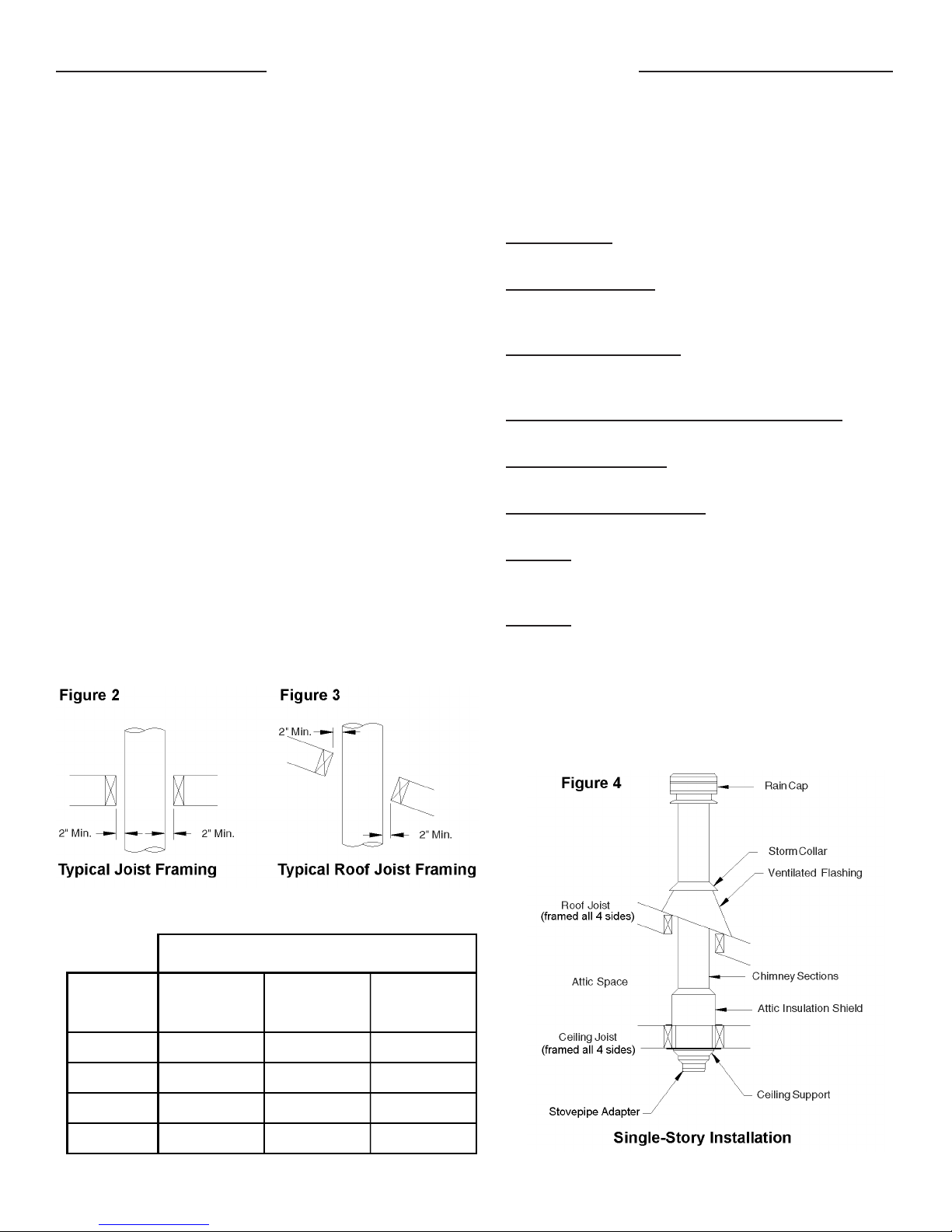
Plan your installation carefully. If possible, position the
stove so that the flue outlet is between joists or rafters.
Drop a plumb line to the center of the flue outlet, and mark
this center point on the ceiling. Lay out and frame in all
openings, ensuring the specified 2-inch clearance to
combustibles is maintained. Refer to Table 1 for framing
dimensions, and mark the appropriate cutting lines around
the center point. All openings should be square (all four
sides), plumb, and in perfect alignment with each other
(Figure 2).
For sloping roofs, ensure that the framing dimension is
measured in the horizontal plane (Figure 3).
Installation Procedures
Ceiling Support Installation
To complete a proper ceiling support installation, the
following parts will or may be required.
• Ceiling Support: Required when supporting a chimney
through a flat level ceiling. Also acts as a firestop.
• Attic Insulation Shield: Required where a chimney
passes from a lower living space into an unoccupied
attic space.
• Firestop Radiation Shield: Required where a chimney
passes from a lower living space into an upper living
space or occupied attic space.
• Roof Flashing Assembly (including Storm Collar):
Required when the chimney penetrates a roof.
• Rafter Radiation Shield: Required when the chimney is
enclosed immediately below the roof.
• Suitable Lengths of Chimney: The chimney diameter
(ID) should be sized to suit the appliance.
• Elbow Kit: To avoid cutting of joists and clear other
obstructions. Kit includes 2 elbows, 1 offset support,
and 4 locking bands.
• Rain Cap: Deluxe model.
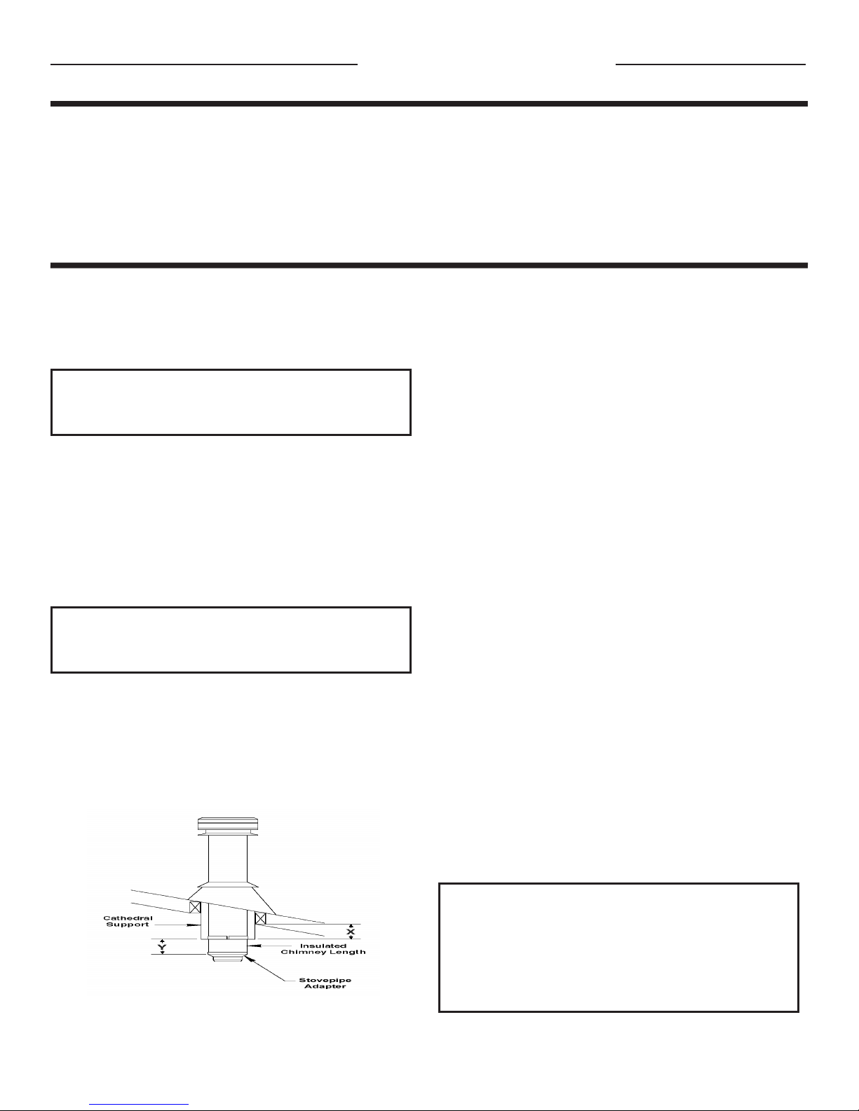
The Model TLC ceiling support will support up to 50 feet
of chimney sections, all of which must be installed above
the support. Figures 4 and 6 show the two most common
types of ceiling support installation. Frame (all four sides)
a level square opening to the dimensions specified in the
Framing Dimensions (Table 1).
Table 1
Chimney
Diameter
Support*
Wall
Thimble*
All
Framing
Tools
Your Model TLC chimney system is designed for
installation using standard building materials and
procedures. The following tools/equipment may be
required, as well as some others, depending on the
location and structure in which the chimney is to be
installed.
• Safety Gloves
• Safety Goggles
• Hammer and Nails • Square
• Tin Snips
• Tape Measure
Framing Details
•
Screwdriver and Pliers
•
Plumb Line and Level
•
Keyhole Saw or Power Jigsaw
•
Caulking Gun
Plan your installation carefully. If possible, position the
stove so that the flue outlet is between joists or rafters.
Drop a plumb line to the center of the flue outlet, and
mark this center point on the ceiling. Lay out and frame
in all openings, ensuring the specified 2-inch clearance to
combustibles is maintained. Refer to Table 1 for framing
dimensions, and mark the appropriate cutting lines around
the center point. All openings should be square (all four
sides), plumb, and in perfect alignment with each other
(Figure 2).
For sloping roofs, ensure that the framing dimension is
measured in the horizontal plane (Figure 3).
Installation Procedures
Ceiling Support Installation
To complete a proper ceiling support installation, the
following parts will or may be required.
• Ceiling Support: Required when supporting a chimney
through a flat level ceiling. Also acts as a firestop.
• Attic Insulation Shield: Required where a chimney
passes from a lower living space into an unoccupied
attic space.
• Firestop Radiation Shield: Required where a chimney
passes from a lower living space into an upper living
space or occupied attic space.
• Roof Flashing Assembly (including Storm Collar):
Required when the chimney penetrates a roof.
• Rafter Radiation Shield: Required when the chimney is
enclosed immediately below the roof.
• Suitable Lengths of Chimney: The chimney diameter
(ID) should be sized to suit the appliance.
• Elbow Kit: To avoid cutting of joists and clear other
obstructions. Kit includes 2 elbows, 1 offset support,
and 4 locking bands.
• Rain Cap: Deluxe model.
The Model TLC ceiling support will support up to 50 feet
of chimney sections, all of which must be installed above
the support. Figures 4 and 6 show the two most common
types of ceiling support installation. Frame (all four sides)
a level square opening to the dimensions specified in the
Framing Dimensions (Table 1).
Framing Dimensions (in inches)
Flue
5" 123/8 x 123/
6" 123/8 x 123/
7" 133/8 x 133/
8" 143/8 x 143/
* When cutting the inside "finished" surface of your wall or
ceiling, cut a "round hole" to the framing dimension.
Ceiling
(Support)
14 x 14 11 x 11
8
14 x 14 12 x 12
8
14 x 14 13 x 13
8
14 x 14 14 x 14
8
Othe r
3
Model TLC All-Fuel Chimney - 5” to 8” Installation Instructions
Table 2
Framing Dimensions
for Attic Insulation Shield
Chimney Flue
Diameter
Slide the trim ring onto the ceiling support, and slide the
assembly into the framed opening from below. Ensure
that the finishing ring is flush with the underside of the
ceiling and the assembly is level and plumb. Secure
the ceiling support in place, using at least three 8-penny
(2½”) nails through each of the four straps or through
the twelve prepunched holes in the support. You may
substitute, in lieu of nails, twelve #8 x 2” wood screws.
Stovepipe Adapter Installation
The stovepipe adapter is installed by twisting-locking it
to the bottom end of the chimney section that enters the
ceiling support. Lower the assembly down into the ceiling
support so that the stovepipe adapter sleeve is protruding
through the support and into the living space.
Attic Insulation Shield Installation
An attic insulation shield must be installed where
the chimney enters an attic space. (It also acts as a
firestop when properly framed.) An attic insulation
shield should keep insulation from coming into contact
with the chimney and will allow a depth of insulation of
10 inches plus the depth of the ceiling joist. Where height
restrictions will not permit the use of the attic insulation
shield, an enclosure from the attic joist to the roof joist will
be sufficient. All chimney enclosures must maintain the
required minimum airspace clearance of 2 inches to the
chimney. When enclosing the chimney below the roof
line, a rafter radiation shield at the roof level and a firestop
radiation shield at the ceiling level must be installed.
inches
The crimped end (stub) of the stovepipe adapter is
intended to fit inside the flue pipe from a solid-fuel
appliance, thus preventing condensate drips at the
chimney connection. Install interconnecting flue pipe
by following the appliance manufacturer’s installation
instructions and appropriate building code requirements,
keeping in mind that the flue pipe run should be as short
and straight as practical. Generally, for a wood-burning
appliance installation, an 18-inch minimum clearance to
combustibles must be maintained for a single-wall flue
pipe.
5" 11 x 11
6" 12 x 12
7" 13 x 13
8" 14 x 14
Install additional chimney sections and lock together by
turning clockwise until the two sections lock together
tightly. Install required locking bands. Continue adding
chimney lengths until a height of about 2 feet below the
next ceiling level is achieved.
4
Hart & Cooley, Inc.
Installation Instructions Model TLC All-Fuel Chimney
For proper installation, the attic opening must be fully
framed at 2 inches of clearance to the chimney pipe
with framing material of the same dimension as the
ceiling joists, per Table 2 (Framing Dimensions for
Attic Insulation Shield). The tabs on the plate of the
attic insulation shield are inserted in the framed opening
around the chimney. Nail the attic insulation shield base
to the framing dimensions with at least two per side, using
2d 1” spiral nails or 1” x #8 wood screws.
When an attic insulation shield is required above the
ceiling support into an attic as shown in Figure 4, ensure
that the base of the shield is flush with the top of the joist
framing, and nail in place. The telescoping portion of
the attic insulation shield will eliminate the need to trim
the bottom, when installed immediately above the ceiling
support. When fully extended, the attic insulation shield
will provide joist shielding when installed in a two-story
main floor application (Figure 6).
If insulation is blown in and adheres to the chimney pipe,
it must be brushed off to eliminate any possible contact of
this material with the chimney surface.
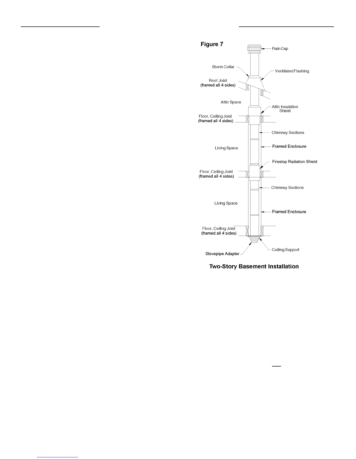
Firestop Radiation Shield Installation
A firestop radiation shield must be installed where the
chimney passes from one living space to another living
space, as shown in Figure 7. It is designed to provide
proper firestopping between floors and to keep direct
radiation from the chimney away from the joist framing.
Install the firestop radiation shield from below the joist
framing, and nail in place using 1” spiral nails. Ensure no
insulation is within the 2-inch airspace clearance around
the chimney. This includes the airspaces between the
firestop radiation shield and the joist framing.
When the chimney is enclosed in the attic area, a firestop
radiation shield must be installed at the ceiling level. If
the base of the firestop radiation shield does not fit flush
with the ceiling frame, measure the distance that the base
is sitting below the framing, and trim that amount off the
top of the firestop radiation shield before securing into
place.
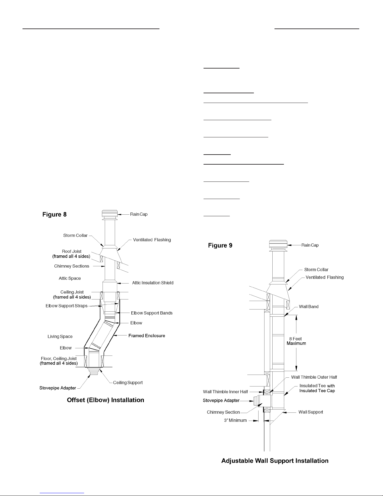
Elbow Installation
Two elbows may be used in an interior installation to
provide an offset, in order to avoid cutting of joists and
to clear other obstructions. Each elbow support will
support 15 feet of chimney, and the maximum length of
chimney allowed between elbows is 6 feet. Forty-five-
degree (45°) elbows may be used only with oil or gas
appliances. See Chart 1 - Offset Chimney Installation
on page 16 of these instructions for details.
The female end of the elbows are not embossed; this
ensures that proper alignment of the chimney system
is maintained. Locking bands must be installed at all
chimney joints, forming an offset.
Hart & Cooley, Inc.
Install the insulated offset elbow on the vertical chimney
length, and position the elbow in the required direction.
Fasten the elbow to the chimney length with the supplied
locking band.
5
Model TLC All-Fuel Chimney - 5” to 8” Installation Instructions
Place the required offset chimney length(s) as per the
Offset Chimney Installation chart for appropriate
length(s). Turn it clockwise to lock it in place and fasten
in place with the supplied locking band.
Install the remaining offset elbow to turn the chimney
back to the vertical position and fasten in place with the
supplied locking band.
During installation, provide supplementary support for the
offset section to avoid undue stress on connected elbows.
Install an elbow support just above the highest elbow.
Attach the support band to the chimney with four of the
nuts and bolts, and then install the four stainless steel
sheet metal screws through the prepunched holes. Attach
the support straps to the support band assembly, and
nail the support straps to the framing using 6d 2” nails or
#8 x 1½” wood screws. See Figure 8.
Never install an elbow in a joist area. Chimney sections
must pass vertically through framed joist areas.
To complete a proper wall support installation, the
following parts will or may be required.
•
Wall Support: Intended for a through-the-wall
installation where the chimney has a horizontal
connection.
•
Stovepipe Adapter: Transition from chimney to flue pipe.
•
Insulated Tee with Insulated Tee Cap: Allowing a
horizontal connection to the chimney.
•
Roof Flashing Assembly: Required when the chimney
penetrates a roof or a roof overhang.
•
Rafter Radiation Shield: Required when the chimney is
enclosed immediately below the roof.
•
Wall Band: Required to provide lateral support to chimney.
•
Suitable Lengths of Chimney: The chimney diameter
should be sized to suit the appliance.
•
Chimney Length: Appropriate length for connection to
tee branch.
•
Wall Thimble: Required to pass though a combustible
wall. It also acts as a firestop.
•
Rain Cap: Deluxe model.
Note: Never offset an exterior chimney.
Note: Never offset an exterior chimney.
Adjustable Wall Support Installation
As previously mentioned, the ideal location for your
chimney system is within the building envelope. A wall
support installation is required when the above-mentioned
location is not possible.
6
Hart & Cooley, Inc.
Installation Instructions Model TLC All-Fuel Chimney
Installation Instructions Model TLC All-Fuel Chimney
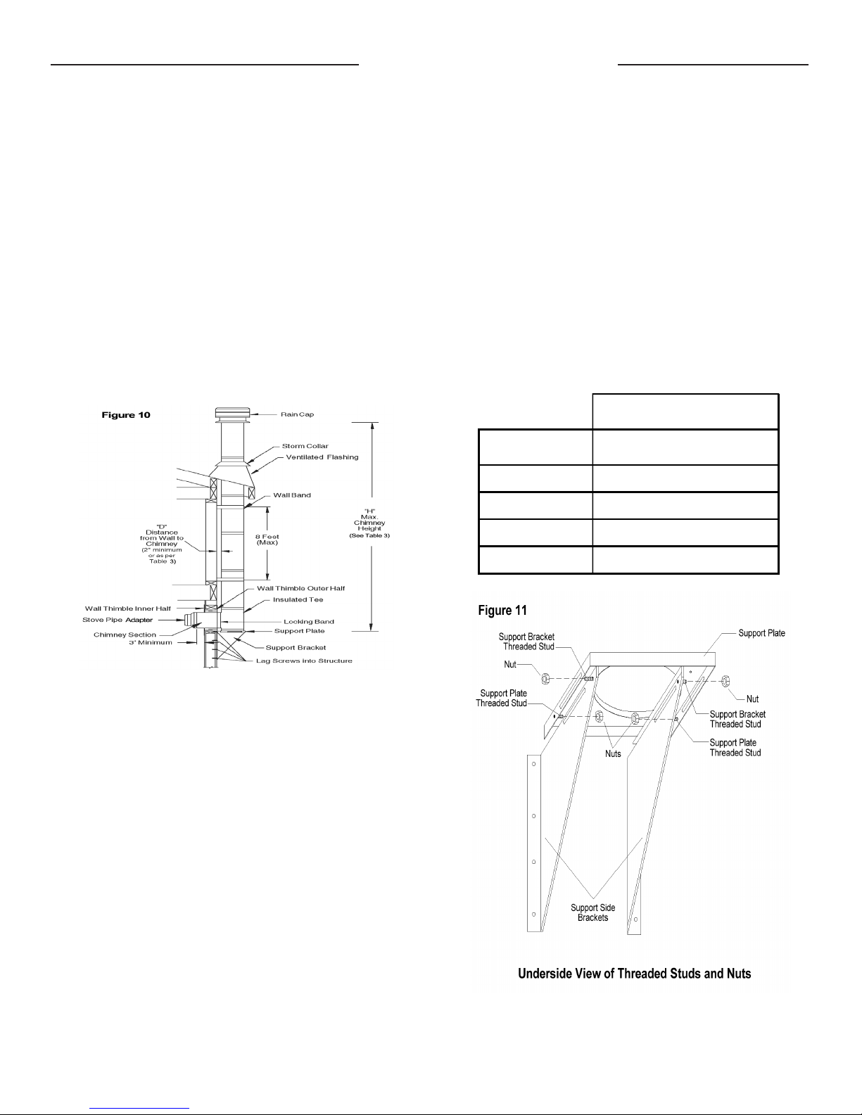
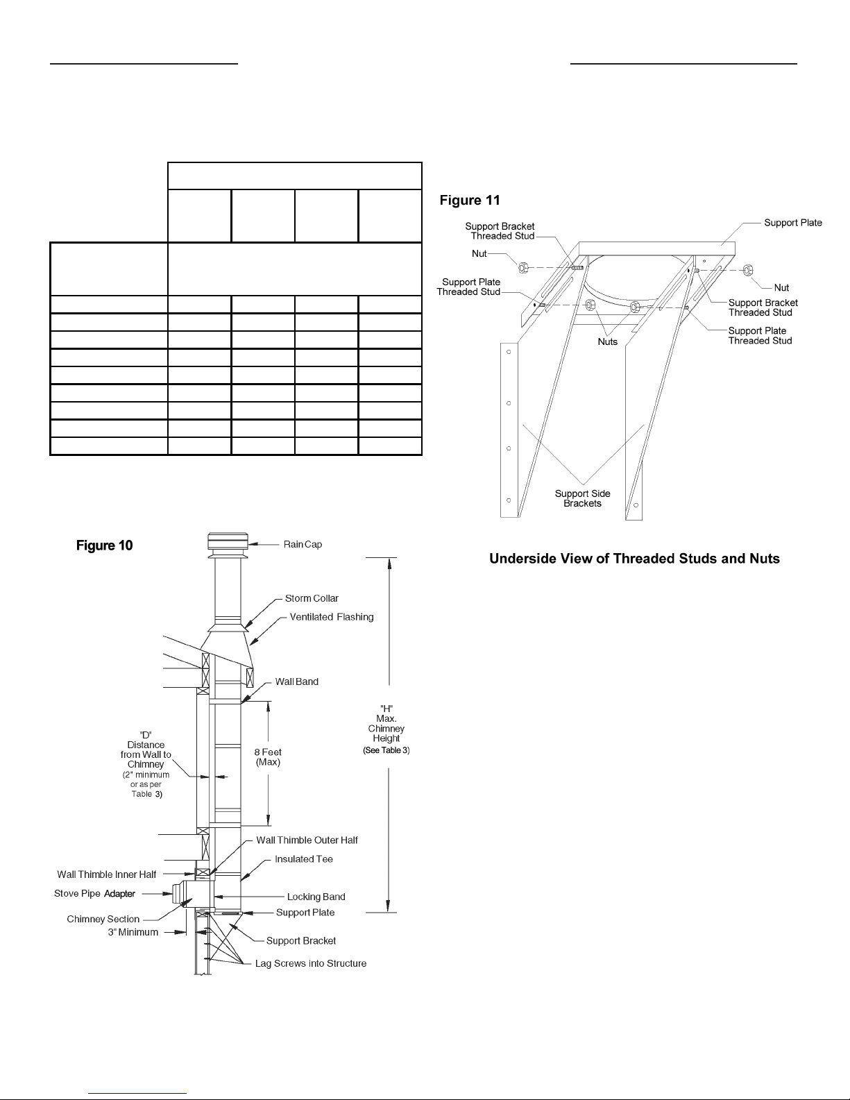
The maximum chimney height above a wall support is
indicated in Table 3 and illustrated in Figure 10, all of
which must be above the support.
The wall support will allow for an adjustment of 2" to 6"
from a vertical wall. Threaded studs are factory-installed
on both side brackets and the support plate for fast and
easy assembly. See Figure 11.
Table 3
D (inches)
Wall to Chimney
H (feet)
Height
The maximum chimney height above a wall support is
indicated in Table 3 and illustrated in Figure 10, all of
which must be above the support.
Wall Support Chimney Height Chart
5" ID
Chimney
Distance from
2 74 63 56 49
2.5 73 62 55 48
3 71 60 53 47
3.5 69 59 51 46
4 66 56 49 44
4.5 62 53 46 42
5 58 50 43 39
5.5 52 45 38 35
6 45 39 34 30
D - Distanc e from wall to the chimney
H - Height of chimney in feet
See Figure 10 also
6" ID
Chimney
Maximum
7" ID
Chimney
8" ID
Chimney
The wall support will allow for an adjustment of 2” to 6”
from a vertical wall. Threaded studs are factory-installed
on both side brackets and the support plate for fast and
easy assembly. See Figure 11.
Ensure that the wall support brackets are bolted securely
to the wall.
The following steps will assist you in the installation of
the wall thimble and of the wall support. Figure 10 shows
a typical wall support installation through a combustible
wall.
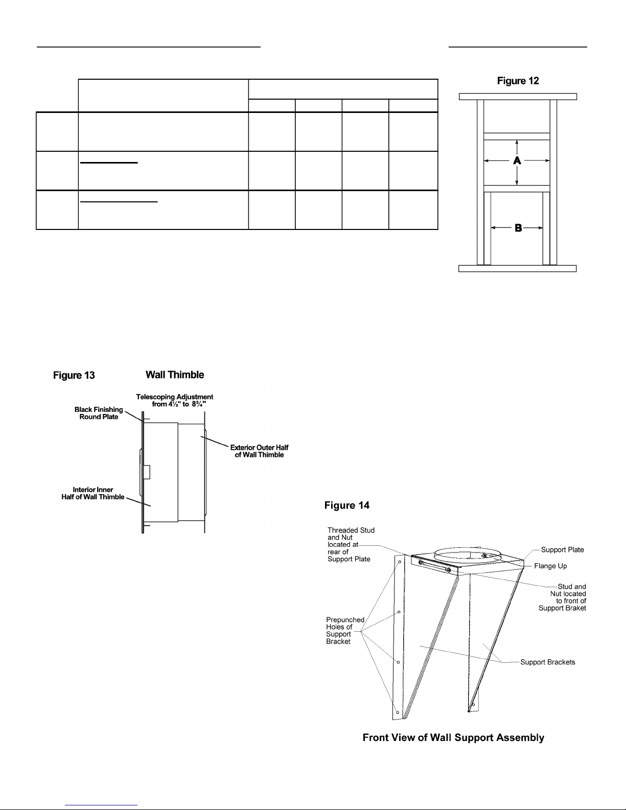
1. Determine the centerline of the horizontal connection
(chimney length through the wall), and frame an
opening to the dimensions for the wall thimble in a
combustible wall. See Table 4 Section A and Figure
12(A).
- Use a stud finder to roughly locate the wall studs.
Mark the outline of the hole and drill a pilot hole in
its center.
- Break out part of the wall covering within the
outline to confirm that the hole will be centered
between studs and that no electrical wires could
be cut by the saw.
2. For a noncombustible wall (concrete block or poured
foundation), cut a hole 3/16” greater in diameter than
the outside diameter of the chimney as per Table 4.
See Table 3 for maximum chimney heights based on
chimney diameter and distance from wall.
Hart & Cooley, Inc.
7
Model TLC All-Fuel Chimney - 5” to 8” Installation Instructions
Model TLC All-Fuel Chimney - 5" to 8" Installation Instructions
5" 6" 7" 8"
Wall Thimble
for Combustible Wall
Support Brackets
for Bracing
Table 4
Chimney SizeFraming Dimensions
Wall Thimble & Support Brackets
Section
A
B
Minimum Round Hole Diameter
for Noncombustible Wall
Minimum Framed Opening
Minimum Framed Opening
3
7
14" x 14" 14" x 14" 14" x 14" 14" x 14"
91/4"9
3. After framing in your opening to the dimensions
specified to the Framing Tables 1 or 3, install the
outer half (with the unfinished square plate) of the wall
thimble into the outside wall opening. Secure in place
using appropriate fasteners through the prepunched
holes.
/16"83/16"93/16" 103/16"
1
/4" 101/4" 111/4"
threaded studs into the oblong slots. See Figures
11 and 14. Install the supplied nuts on the threaded
studs until snug. Do not tighten at this time, as
adjustments may be required. Set aside and prepare
the support bracing to secure the side brackets as per
Framing Dimensions Table 4 Section B and Figure
12(B).
Two options are described hereafter for the installation of
the wall support and the insulated tee assembly. Follow
Method A if inserting an assembled insulated chimney
length and insulated tee into the wall thimble prior to
the wall support. Follow Method B if securing of the
wall support to the wall prior to the insulated tee and the
insulated chimney length.
4. Install the inner half (with round plate) of the wall
thimble into the inside wall opening, ensuring that the
shield slides over the shield of the outer half. Once
in place and flush against the wall, install the black
finishing trim plate onto the wall surface and fasten
in place with appropriate fasteners through the four
prepunched holes.
Note: To stop cold air infiltration into the dwelling,
you can install the optional universal shielding
insulation into the wall thimble. See separate
installation instructions packaged with the
universal shield insulation.
5. Assemble the two side brackets (point of triangle
facing down) to the support plate (flange up and
threaded stud toward the wall) by inserting the
8
Hart & Cooley, Inc.
 Loading...