

Harsco Industrial SC-1500, SC-2000, SC-3000, SC-4000, SC-1500GG Installation & Owner's Manual
...
&
P-K SONIC® GAS FIRED BOILER
w/ NURO® CONTROL SYSTEM
Natural Gas or Propane Gas
SC-1500/SC-2000/SC-3000/SC-4000
Dual Fuel
SC-1500GG/SC-2000GG
SC-3000GG/SC-4000GG
Part # 1004905978
C.S.A Design-Certified
Complies with ANSI Z21.13/CSA 4.9
Gas-Fired Low Pressure Steam and Hot Water Boilers
ASME Code, Section IV
Certified by Patterson-Kelley
C.S.A Design-Certified
Complies with ANSI Z21.13/CSA 4.9
Gas-Fired Low Pressure Steam and Hot Water Boilers
Model Number:
Serial Number:
Start-Up Date:
Harsco Industrial, Patterson-Kelley
155 Burson Street
East Stroudsburg, PA 18301
Telephone: 570.476.7261
Toll Free: 877.728.5351
Fax: 570.476.7247 www.harscopk.com
Released June 2, 2017
INSTALLATION
&
OWNER’S
MANUA
L
INSTALLATION
&
OWNER’S
MANUA
L
INSTALLATION
&
OWNER’S
MANUA
L
INSTALLATION
&
OWNER’S
MANUA
L
INSTALLATION
&
OWNER’S
MANUA
L
INSTALLATION
&
OWNER’S
MANUA
L
INSTALLATION
&
OWNER’S
MANUA
L
INSTALLATION
&
OWNER’S
MANUA
L
The information in this manual is the property of Harsco Industrial Patterson-Kelley. The descriptions and specifications contained in this
manual were in effect at the time this manual was approved for publication. While Harsco Industrial Patterson-Kelley will continue to
support earlier model boilers to within a reasonable time limit, we reserve the right to discontinue models and replacement parts at any
HARSCO Industrial, Patterson-Kelley 2017: All Rights Reserved.
time or change specifications or design without notice and without incurring any obligation.
P-K SONIC® Gas Fired Boiler
Technical Service 1.877.728.5351
General
P-K SONIC® SC-1500, SC-2000, SC-3000 and SC-4000
All P-K SONIC® SC-1500, SC-2000, SC-3000 and SC-4000
Gas-Fired Boilers must be:
• Installed, operated, and serviced in accordance with
instructions contained in this manual and other supplemental
manuals.
• Installed by qualified personnel in accordance with designs
prepared by qualified facility engineers including: structural,
mechanical, electrical, and other applicable disciplines.
• Operated and serviced in accordance with a comprehensive
safety program determined and established by the customer.
Do not attempt to operate or service until such a program
has been established.
• Operated and serviced by experienced, qualified, and
properly trained personnel in accordance with all applicable
codes, laws, and regulations.
Safety Precautions
Provide a suitable location for the boiler, away from normal
personnel traffic, with adequate working space, adequate
clearances, proper ventilation and lighting, with a structure
sufficiently strong and rigid to support the weight of the boiler, all
piping, and accessories.
NOTICE!
Each safety device must be
maintained and checked per the
recommended schedule. Refer to
Maintenance.
SAFETY FEATURES
It is the responsibility of the
customer to ensure external
safety provisions, such as but not
limited to: guards, safety labels,
safety controls, interlocks, lockout
devices are in place and operable.
SAFETY LABELS
The following words are used in
this manual to denote the degree
of seriousness of the individual
hazards.
Indicates an imminently
hazardous situation which,
if not avoided, will result in
death or serious injury. This
signal word is to be limited
to the most extreme
situations.
Indicates a potentially
hazardous situation which, if
not avoided, could result in
death or serious injury.
Indicates a potentially
hazardous situation which, if
not avoided, may result in
minor or moderate injury. It
may also be used to alert
against unsafe practices.
NOTICE/NOTE - NOTICE
The preferred signal word to
address practices not related to
personal injury. The safety alert
symbol is not used with this signal
word.
Safety
P-K SONIC® Gas Fired Boiler
Technical Service 1.877.728.5351
NOTICE!
The safety labels shown below are
affixed to your boiler. Although the
labels are of high quality, they may
become dislodged or unreadable
over time. Contact Harsco
Industrial, Patterson-Kelley at
570.476.7261 or toll-free at
877.728.5351 for replacements.
Gas may lose its odor. Proper gas
sensing equipment and procedures
should be used for leak checks.
Failure to detect gas leaks could
result in injury or death.
Training
Proper training is the best protection against accidents. It is
essential to read, understand, and follow the recommendations
of this manual before installing, operating, or servicing this
equipment. Failure to do so could result in fire or explosion and
serious injury, death, and/or property damage.
Operating and service personnel must be thoroughly familiar with
the basic construction of the P-K SONIC® SC-1500, SC-2000,
SC-3000 and SC-4000 boilers, the use and locations of th e
controls, the operation of the boilers, adjustment of their various
mechanisms, and all applicable safety precautions. If any of the
provisions of this manual are not fully and completely
understood, contact Harsco Industrial, Patterson-Kelley Technical
Service at 570.476.7261 or toll free at 877.728.5351.
Hazard Warnings
Electrical Hazards
Shock Hazard! Properly Lockout/Tagout the
electrical service and all other energy sources
before working on or near the boiler.
Shock Hazard! Do not spray water directly on
this boiler or any electrical components.
Electrical Hazard! Do not alter wiring
connections.
Crush Hazards
Lifting Hazards! Use properly rated lifting
equipment to lift and position the boiler. The
load is unbalanced. Test the balance before
lifting off the floor. Do not allow personnel
beneath the lifted load. Refer to the
approximate weights in the table below.
Boiler Model
Weight in
Pounds
Dual Fuel
Model
Weight in
Pounds
SC-1500
1,450 lbs.
SC-1500GG
1,550 lbs.
SC-2000
1,450 lbs.
SC-2000GG
1,550 lbs.
SC-3000
1,850 lbs.
SC-3000GG
2,000 lbs.
SC-4000
1,900 lbs.
SC-4000GG
2,000 lbs.
Bump Hazard from Overhead Ductwork and Piping
Pressure Hazards
Injury Hazard! Install components with adequate vertical clearance.
Pressure Hazard! Hot fluids. Install isolation valves on boiler water inlet and outlet.
Make sure isolation valves are closed before servicing boiler.
Pressure Hazard! Hot fluids. Annually test safety relief valve(s) for proper operation.
Do not operate boiler with faulty relief valve(s).
P-K SONIC® Gas Fired Boiler
Technical Service 1.877.728.5351
Slip, Fall Hazards
Tripping Hazard! Do not install piping on floor surfaces. Maintain a clear path around
the boiler.
Slip and Fall Hazard! Use a drip pan to catch water while draining the boiler. Maintain
dry floor surfaces.
Slip and Fall Hazard! Do not locate intake or exhaust terminations above a walkway;
dripping of condensate can cause icing of the walking surface. Refer to 2.5.5 for more
information.
Fall Hazard! Do not stand on boiler.
Chemical Hazards
Chemical Hazards from Cleaning Products. Use
caution when cleaning the system. The use of
professional assistance is recommended. Use safe
procedures for the disposal of all cleaning solutions.
Combustion Condensate – An acidic pH of
approximately 3.0 to 5.0 can be expected. Use PVC,
CPVC, or other corrosion resistant piping for drainage. Collection and disposal must be in accordance
with all applicable regulations. A condensate neutralization kit is available. Please contact your local
Harsco Industrial, Patterson-Kelley representative for more information.
Burn, Fire and Explosion Hazards
Burn, fire, and explosion hazards! Installation must be in strict conformance to all applicable codes
and standards including NFPA 54, ANSI Z223.1 and CAN/CSA B.149. Install all required
vent lines for gas devices. Refer to 3.4 and 3.5 for more information.
Hazard from Incorrect Fuels! Possible fire, explosion, overheating, and damage. Do not
use any fuels except the design fuels for the unit.
Overfire Hazards! High pressure in gas supply could result in overfiring of this or other
devices supplied from the same source.
Fire and Explosion Hazards! Close the main gas shutoff before servicing boiler.
Fire and Explosion Hazards! Do not store or use gasoline or other flammable vapors or
liquids in the vicinity of this or any other gas fired appliance.
Burn hazard! Possible hot surfaces. Do not touch gas vent during firing operation. Use
only factory recommended vent components.
Burn Hazard! Pipes, vents, and boiler components could be hot. Do not touch piping or stack surfaces
during operation or immediately after shutdown of the boiler.
Burn Hazard! Hot flue! Use caution when servicing or draining boiler.
Fire and Explosion Hazards! Use caution when servicing burner. Propane (LPG) is heavier than air
and may linger in the combustion chamber, vent lines, or elsewhere.
Gas Leak Hazard! Make sure the burner is installed correctly and blower/transition is securely fastened
following any maintenance performed on them. These connections may leak gas if assembled
incorrectly.
Gas Leak Hazard! All threaded gas connections must be made using a pipe compound that is resistant
to liquefied petroleum gas. Do not use Teflon™ tape on threaded ga s piping.
Gas Leak Hazard! Check entire gas train for leaks after installation. If there is a smell of gas, shut down
the boiler and obtain immediate assistance from trained service personnel and/or your local fire
department.
Overfire Hazard! Possible fire and explosion from excess gas pressure. Make sure that gas inlet
pressure does not exceed 14 inches W.C.
Overfire Hazard! Possible fire and explosion. Possible malfunction of regulators and/or gas safety shut
off/control valves. Maintain all gas train components in good condition. Do not alter wiring connections.
Annual inspection by factory-trained personnel for proper set-up and operation is recommended.
Overfire and Underfire Hazards! Possible fire, explosion, overheating, and component failure. Do not
attempt to adjust firing rate of the boiler. The firing rate must be adjusted only by factory trained
personnel.
P-K SONIC® Gas Fired Boiler
Technical Service 1.877.728.5351
Revised: June 2, 2017
Released: June 2, 2017
HARSCO Industrial, Patterson-Kelley 2017
All Rights Reserved.
1004905978 P-K SONIC NURO Installation and
Owners Manual (Rev F Jun-2017).docx
Page v
Table of Contents
1 INTRODUCTION .......................................................................................................................... IX
1.1 PURPOSE OF THIS DOCUMENT .................................................................................................. 1
1.2 COMMON ABBREVIATIONS ........................................................................................................ 1
2 SITE PREPARATION .................................................................................................................... 2
2.1 INITIAL INSPECTION UPON RECEIVING ........................................................................................ 2
2.2 STORAGE PRIOR TO INSTALLATION ............................................................................................ 2
2.3 COMPLIANCE WITH CODES ........................................................................................................ 3
2.4 LOCATION SETUP ..................................................................................................................... 4
Foundation ......................................................................................................................... 4
Clearances ......................................................................................................................... 5
2.5
2.6 GAS PIPING CONSIDERATIONS ................................................................................................ 11
2.7 WATER QUALITY STANDARD ................................................................................................... 11
3 INSTALLATION ........................................................................................................................... 11
I
NLET AIR AND EXHAUST VENTING CONSIDERATIONS
.................................................................. 6
Applicable Codes and Standards ........................................................................................ 6
Combustion Air Inlet Planning (United States and Canada Considerations) ....................... 6
Category II/IV Flue Gas Exhaust Vent Planning ................................................................. 7
Venting Materials for Flue/Exhaust Systems ....................................................................... 8
Required Clearances .......................................................................................................... 9
3.1 OVERVIEW ............................................................................................................................. 11
3.2 APPLIANCE CONNECTIONS ...................................................................................................... 11
Appliance Connections (SC-1500 & SC-2000) ................................................................. 12
Appliance Connections (SC-3000 & SC-4000) ................................................................. 12
3.3 ELECTRICAL CONNECTIONS .................................................................................................... 13
Power Requirements (SC-1500 & SC-2000) ..................................................................... 13
Single Phase Power Supply Connection (SC-1500 & SC-2000) ....................................... 13
Power Requirements (SC-3000 & SC-4000) ..................................................................... 14
Three Phase Power Supply Connection (SC-3000 & SC-4000) ........................................ 14
High Voltage (TB2) Terminal Block (SC1500 & SC2000) ................................ .................. 16
High Voltage (TB2) Terminal Block (SC3000 & SC4000) ................................ .................. 18
Low Voltage (TB1) Terminal Block .................................................................................... 20
3.4 COMBUSTION AIR ................................................................................................................... 22
Air Inlet Requirements – United States ............................................................................. 22
Air Inlet Requirements - Canada ....................................................................................... 23
P-K SONIC® Combustion Air Requirements ................................................................ ..... 24
Direct Vent / Sealed Combustion Installations .................................................................. 24
Motorized Combustion Air Dampers ................................................................................. 25
3.5 FLUE GAS / EXHAUST VENTING ............................................................................................... 27
Category II or IV Venting Installation................................................................................. 27
Vent Termination ............................................................................................................... 28
Venting for Multiple Boilers................................................................................................ 29
Sealed Combustion/Direct Vent Systems .......................................................................... 30
Inlet Duct Connection to Boiler .......................................................................................... 30
Intake Duct Materials and Sizes ....................................................................................... 30
Category II Installations .................................................................................................... 30
Category IV Installations ................................................................................................... 32
Stainless Steel Venting ..................................................................................................... 32
P-K SONIC® Gas Fired Boiler
Technical Service 1.877.728.5351
Revised: June 2, 2017
Released: June 2, 2017
HARSCO Industrial, Patterson-Kelley 2017
All Rights Reserved.
1004905978 P-K SONIC NURO Installation and
Owners Manual (Rev F Jun-2017).docx
Page vi
CPVC Vent System Installation..................................................................................... 32
3.6 REMOVING AN EXISTING BOILER ............................................................................................. 33
3.7 PIPING ................................................................................................................................... 34
Gas Piping Overview ........................................................................................................ 34
Natural Gas Piping ........................................................................................................... 35
Propane Gas Piping ......................................................................................................... 35
Pressure Testing the Gas Piping ...................................................................................... 35
Boiler Water Piping ........................................................................................................... 36
Boiler Inlet and Outlet Connections ................................................................................... 36
Boiler Water Piping (for Installer) ...................................................................................... 37
3.8 WATER QUALITY .................................................................................................................... 38
3.9 PRE-START CHECKLIST .......................................................................................................... 39
3.10 SAFETY CHECKS ................................................................................................................... 39
Ignition Safety System Test .......................................................................................... 39
Low Water Cut-Out Test ................................................................ ............................... 39
Manual Reset High Temperature Limit Test ..................................................................... 40
Gas Pressure Switch Tests ........................................................................................... 40
3.11 FUEL/AIR ADJUSTMENTS ........................................................................................................ 41
Gas Pressure Adjustment ............................................................................................. 41
Manual Control Mode for High and Low Fire Adjustment .............................................. 42
Adjusting High Fire ....................................................................................................... 43
Adjusting Low Fire ........................................................................................................ 43
Checking Flame Signal ................................................................................................. 43
3.12 INITIAL NURO CONTROL SETUP AND ADJUSTMENT .................................................................. 44
Startup .......................................................................................................................... 44
Home Screen ................................................................................................................ 45
Information Screen ....................................................................................................... 45
Setup Wizard ................................................................................................................ 46
TYPICAL BOILER OPERATING CONDITIONS ............................................................................... 46
3.13
4 DUAL FUEL BOILER OPERATION ............................................................................................ 47
4.1 OVERVIEW ............................................................................................................................. 47
4.2 CHANGING FUEL TYPES .......................................................................................................... 47
4.3 P-K SONIC SC1500GG & SC2000GG .................................................................................. 48
Natural Gas Train and Propane Gas Train Locations (SC1500GG & SC2000GG) ........... 48
Fuel Selector Switch Location........................................................................................... 49
4.4 P-K SONIC SC3000-SC4000................................................................................................ 50
Natural Gas Train and Propane Gas Train Locations (SC3000GG & SC4000GG) ........... 50
Fuel Selector Switch Location........................................................................................... 51
5 OPERATIONS ................................................................ ............................................................. 52
5.1 NURO
®
CONTROL PANEL ....................................................................................................... 52
NURO Touch Screen Interface ................................................................ ......................... 52
Factory Tests .................................................................................................................... 52
5.2 NORMAL LIGHTING AND SHUT-DOWN PROCEDURES ................................................................. 53
Normal Lighting Procedures ............................................................................................. 53
Normal Shut Down Procedures ......................................................................................... 53
5.3 EMERGENCY SHUT-OFF ......................................................................................................... 53
6 MAINTENANCE .......................................................................................................................... 54
6.1 PREVENTATIVE MAINTENANCE ................................................................................................ 54
P-K SONIC® Gas Fired Boiler
Technical Service 1.877.728.5351
Revised: June 2, 2017
Released: June 2, 2017
HARSCO Industrial, Patterson-Kelley 2017
All Rights Reserved.
1004905978 P-K SONIC NURO Installation and
Owners Manual (Rev F Jun-2017).docx
Page vii
Daily Preventative Maintenance ....................................................................................... 54
Weekly Preventative Maintenance .................................................................................... 54
Monthly Preventative Maintenance ................................................................................... 55
Semi-Annually .................................................................................................................. 55
Annually ........................................................................................................................... 55
6.2 MAINTENANCE AND INSPECTION SCHEDULE ............................................................................. 56
6.3 CLEANING THE BURNER & COMBUSTION CHAMBER .................................................................. 56
6.4 AFTER REPAIRS OR MAINTENANCE.......................................................................................... 58
6.5 SEQUENCE OF OPERATIONS ................................................................................................... 59
6.6 TROUBLESHOOTING ............................................................................................................... 60
Loss of Power ................................................................................................................... 60
Loss of Water Level .......................................................................................................... 60
Low Gas Pressure ............................................................................................................ 60
High Gas Pressure ........................................................................................................... 60
High Water Temperature ................................................................................................... 60
Low Air ............................................................................................................................. 60
Flame Failure ................................................................................................................... 61
Flame Error ...................................................................................................................... 61
Flue Problem .................................................................................................................... 61
7 PARTS/TECHNICAL SUPPORT ................................................................................................. 62
7.1 TERMINAL BLOCK ASSIGNMENTS ............................................................................................. 63
Terminal Block Assignments — Low Voltage (TB1) Terminal Block .................................. 63
Terminal Block Assignments — High Voltage (TB2) Terminal Block .................................. 64
7.2 WIRING DIAGRAMS ................................................................ ................................................. 65
SC-1500 & SC-2000 Natural Gas or Propane Gas ........................................................... 65
SC-1500 & SC-2000 Dual Fuel ......................................................................................... 67
Wiring Diagram – Power Box (SC-3000 and SC-4000 Only) ............................................ 70
SC-3000 & SC-4000 Control Transformer Diagrams ........................................................ 71
SC-3000 & SC-4000 240V Natural Gas or Propane Gas .................................................. 73
SC-3000 & SC-4000 240V Dual Fuel ................................................................................ 75
SC-3000 & SC-4000 480V Natural Gas or Propane Gas .................................................. 78
SC-3000 & SC-4000 480V Dual Fuel ................................................................................ 80
7.3 BOILER PARTS IDENTIFICATION (SC-1500 & SC-2000) ............................................................ 83
Main Boiler Assembly (SC-1500 & SC-2000) .................................................................... 83
NURO Control Panel (SC-1500 & SC-2000) ..................................................................... 84
Heat Exchanger Assembly (SC-1500 & SC-2000) ............................................................ 85
Natural Gas Train, Burner & Blower Assembly (SC-1500 & SC-2000) .............................. 86
Propane Gas Train, Burner & Blower (SC-1500 & SC-2000) ............................................ 87
7.4 BOILER PARTS IDENTIFICATION (SC-3000 & SC-4000) ............................................................ 88
Main Boiler Assembly (SC-3000 & SC-4000) .................................................................... 88
NURO Control Panel (SC-3000 & SC-4000) ..................................................................... 89
Main Power Box (SC-3000 & SC-4000) ............................................................................ 90
Heat Exchanger Assembly (SC-3000 & SC-4000) ............................................................ 91
Natural Gas Train, Burner & Blower Assembly (SC-3000 & SC-4000) .............................. 92
Propane Gas Train (SC-3000 & SC-4000) ........................................................................ 93
8 P-K SONIC® SPECIFIC LIMITED WARRANTY ........................................................................... 94
9 BOILER FIRE-TEST REPORT .................................................................................................... 96
APPENDIX A – MAINTENANCE LOG ................................................................................................ 97
P-K SONIC® Gas Fired Boiler
Technical Service 1.877.728.5351
Revised: June 2, 2017
Released: June 2, 2017
HARSCO Industrial, Patterson-Kelley 2017
All Rights Reserved.
1004905978 P-K SONIC NURO Installation and
Owners Manual (Rev F Jun-2017).docx
Page viii
APPENDIX B – BOILER ALTITUDE DERATE SCHEDULE ................................ ............................... 98
APPENDIX C – WATER QUALITY STANDARDS QUALITY STANDARDS FOR HYDRONIC
BOILERS IN MULTI-METAL SYSTEMS ............................................................................................. 99
APPENDIX D – BEST PRACTICES FOR NEW & RETROFIT SYSTEMS ........................................ 100
APPENDIX E – INSTALLATION AND QUICK REFERENCE ........................................................... 102
FUEL/GAS SUPPLY .......................................................................................................................... 102
ELECTRICAL/POWER SUPPLY ........................................................................................................... 102
EXHAUST VENTING .......................................................................................................................... 102
APPLIANCE CONNECTIONS (SC-1500 & SC-2000) ............................................................................ 103
APPLIANCE CONNECTIONS (SC-3000 & SC-4000) ............................................................................ 103
HYDRONICS/WATER FLOW ............................................................................................................... 104
PROPYLENE GLYCOL FLOW .............................................................................................................. 105
P-K SONIC® Gas Fired Boiler
Technical Service 1.877.728.5351
Revised: June 2, 2017
Released: June 2, 2017
HARSCO Industrial, Patterson-Kelley 2017
All Rights Reserved.
1004905978 P-K SONIC NURO Installation and
Owners Manual (Rev F Jun-2017).docx
Page ix
If the information in this manual
is not followed, fire or explosion
may result causing property
damage, personal injury, or loss
of life.
Do not store or use gasoline or other
flammable vapors or liquids in the
vicinity of this or any other
appliance. Installation and service
must be performed by a qualified
installer, service agency, or the gas
supplier.
WHAT TO DO IF YOU SMELL GAS:
Do not try to light any
appliance.
Do not touch any electrical
switch; do not use any phone in
your building.
Immediately call your gas
supplier from a neighbor’s
phone. Follow the gas
supplier’s instructions.
If you cannot reach your gas
supplier, call the fire department.
It is essential to read,
understand, and follow the
recommendations of this manual
before installing, operating or
servicing this equipment. Failure
to do so could result in personal
injury or death.
Installation and service must be
performed by a qualified and
knowledgeable individual who
has been certified on the P-K
SONIC® boiler. The features
which permit this boiler to
achieve high-efficiency
performance can be misused
which could result in personal
injury or death.
NOTICE! This manual covers single fuel P-K SONIC®
boilers (Natural Gas –or– Propane Gas) AND dual fuel P-K
SONIC boilers (Natural Gas –and– Propane Gas).
1 Introduction
This manual describes the installation and operation of the
following P-K SONIC® boilers featuring NURO® controls.
SC-1500 & SC-2000:
Natural Gas, 208-240V (single phase)
Propane Gas, 208-240V (single phase)
SC-1500GG & SC-2000GG:
Dual Fuel, 208-240V (single phase)
SC-3000 & SC-4000:
Natural Gas, 208-240V (three phase)
Propane Gas, 208-240V (three phase)
Natural Gas, 440-480V (three phase)
Propane Gas, 440-480V (three phase)
SC-3000GG & SC-4000GG:
Dual Fuel, 208-240V (three phase)
Dual Fuel, 440-480V (three phase)
Individual differences between boiler models will be called out
and defined in separate sections and the titles of these sections
will include the boiler model number. If the boiler model numbers
are not listed in the section title, that section is common to all
boiler models.
If you have any questions on the information contained within, or
do not fully and completely understand the content, please
contact Harsco Industrial, Patterson-Kelley Technical Service at
570.476.7261 or toll free at 877.728.5351.
The P-K SONIC® gas-fired boiler is fully modulating using a
variable speed combustion blower, sophisticated microprocessor
controls, modulating gas safety shut off / control valves and a
unique stainless steel heat exchanger capable of operating in a
fully condensing mode to provide maximum efficiency in a
minimum amount of space. The high-quality materials and
design of the boiler should provide years of trouble-free service if
the instructions in this manual are followed carefully.
The boiler is only a part of the complete heating system. This
boiler may be fully operational but because of poor circulation,
improper control, or other site related characteristics, not deliver
heat to the desired location. Additional equipment such as
temperature sensors, pumps, flow switches, balancing valves,
and check valves will be required for satisfactory operation of any
system. Harsco Industrial, Patterson-Kelley cannot be
responsible for the design or operation of such systems and a
qualified engineer or contractor must be consulted.
While details may differ slightly, basic operation is the same for all
models. Boilers may be built to operate with natural gas or liquefied petroleum gas (propane). Check the
rating plate for correct fuel usage and gas pressures.
P-K SONIC® Gas Fired Boiler
Technical Service 1.877.728.5351
Revised: June 2, 2017
Released: June 2, 2017
HARSCO Industrial, Patterson-Kelley 2017
All Rights Reserved.
1004905978 P-K SONIC NURO Installation and
Owners Manual (Rev F Jun-2017).docx
Page 1
Abbreviation
Description
AMP
Ampere or Amperage
ANSI
American National Standards Institute
ASME
American Society of Mechanical Engineers
AWG
American Wire Gauge
BTU
British Thermal Unit
CH
Comfort Heat
CO2
Carbon Dioxide
CSA
Canadian Standards Association
CSD-1
Controls and Safety Devices
CPVC
Chlorinated Polyvinyl Chloride
DHW
Domestic Hot Water
HWR
Heating Water Return / Hot Water Return (From Building)
HWS
Heating Water Supply / Hot Water Supply (To Building)
ID
Inside Diameter
MBH
Thousands of BTU / Hour
MODBUS
A serial communication protocol (not an abbreviation)
NFPA
National Fire and Protection Agency
NTC
Negative Temperature Coefficient
O2
Oxygen
OD
Outside Diameter
OEM
Original Equipment Manufacturer
SCFM
Standard Cubic Feet per Minute
SMACNA
Sheet Metal and Thermoplastic Duct Construction Manual Air Conditioning
Contractors National Association
TB<#>
Terminal Block (1, 2, 3 etc.)
VAC
Volts Alternating Current
VDC
Volts Direct Current
1.1 Purpose of this Document
It is the purpose of this Installation and Owner’s Manual is to provide complete documentation support
for P-K SONIC
®
boilers featuring NURO controls. Harsco Industrial, Patterson-Kelley is constantly
seeking ways to produce high quality HVAC products. Our operation is based on the premium quality
control program and insures that Harsco Industrial manufactures quality products.
The primary concern of all Harsco Industrial, Patterson-Kelley equipment installation procedures is
Safety. Safety instructions and considerations are presented and repeated throughout the document
as needed. If you have any questions on the information contained within, or do not fully and
completely understand the content, please contact Harsco Industrial, Patterson-Kelley Technical
Service at 570.476.7261 or toll free at 877.728.5351.
1.2 Common Abbreviations
P-K SONIC® Gas Fired Boiler
Technical Service 1.877.728.5351
Revised: June 2, 2017
Released: June 2, 2017
HARSCO Industrial, Patterson-Kelley 2017
All Rights Reserved.
1004905978 P-K SONIC NURO Installation and
Owners Manual (Rev F Jun-2017).docx
Page 2
Installation and service must be
performed by a qualified
installer, service agency, or gas
supplier. Failure to install the
equipment in accordance with
this manual could result in an
unsafe operating condition.
NOTICE!
Controls and other equipment that
are damaged or fail due to
weather exposure are not covered
by warranty.
The boiler is heavy and requires
additional technicians to
support and move the unit(s)
during installation. Use
extreme caution to avoid
dropping the boiler or cause
any bodily injury while lifting or
handling. When positioning
this boiler, maintain positive
control of it at all times. Do not
attempt to move the boiler on
surfaces that are not level.
Failure to heed this warning
could result in personal injury
or death.
NOTICE!
The boiler may be installed on a
combustible floor; however, the
boiler must never be installed on
carpeting.
Bumping hazard from overhead
ducts! Install all components
with adequate vertical
clearances. Insufficient
clearance can restrict the
service access, increasing the
possibility of injury.
NOTICE! Note any damage, suspected potential damage,
or shortage of materials on the freight bill and immediately
notify the carrier. File all claims for shortage or damage with
the carrier. Claims for hidden damages must be filed with
your carrier within 7 days. The carton is equipped with a
“Tip (N) Tell”. If the “Tip (N) Tell” arrow point is blue, that
indicates the package has been on its side or tipped over in
transit.
NOTICE! Controls and other equipment that are damaged
or fail due to weather exposure are not covered by warranty.
2 Site Preparation
2.1 Initial Inspection upon Receiving
Upon receiving the boiler, inspect it for signs of shipping
damage. Some damage may be hidden. Unpack the boiler,
open the front and side doors and inspect the boiler. Verify that
the total number of pieces shown on the packing slip agrees
with those actually received.
2.2 Storage Prior to Installation
If the boiler is not installed immediately, it must be stored in a
location adequately protected from the weather, preferably
indoors. If this is not possible, then it should remain in the
shipping container and be covered by a tarpaulin or other
waterproof covering.
P-K SONIC® Gas Fired Boiler
Technical Service 1.877.728.5351
Revised: June 2, 2017
Released: June 2, 2017
HARSCO Industrial, Patterson-Kelley 2017
All Rights Reserved.
1004905978 P-K SONIC NURO Installation and
Owners Manual (Rev F Jun-2017).docx
Page 3
SC-1500 & SC-2000
SC-3000 & SC-4000
Code of Construction
(Boiler)
ASME Section IV – “H”
(Latest Edition)
ASME Section IV – “H”
(Latest Edition)
Code of Construction
(Economizer)
ASME Section VIII – Div. 1 –
“U” (Latest Edition)
Maximum Allowable Working
Pressure
160 PSIG
Maximum Allowable Design
Temperature
210° F
Hi-Limit Setpoint
200° F
Maximum Setpoint
185° F
2.3 Compliance with Codes
Each P-K SONIC® boiler with standard components complies with American National Standard/CSA
Standard ANSI Z21.13/CSA 4.9, latest edition for Gas-Fired Low Pressure Steam and Hot Water
Boilers.
The P-K SONIC® SC-1500, SC-2000, SC-3000 and SC-4000 heat exchangers are constructed and
stamped in accordance with ASME Boiler and Pressure Vessel Code, Section IV for 160 psig maximum
pressure and 210°F maximum temperature. Other codes or approvals which apply will be labeled on
the boiler.
Installation of the boiler must conform to all the requirements of all national, state and local codes
established by the authorities having jurisdiction or, in the absence of such requirements, to the
National Fuel Gas Code, ANSI Z223.1/NFPA 54 latest edition in the U.S. In Canada, the equipment
shall be installed in accordance with the current Installation Code for Gas Burning Appliances and
Equipment, CAN/CSA-B.149, latest edition, and applicable Provincial Regulations for the class, which
should be carefully followed in all cases. Authorities having jurisdiction should be consulted before
making any installation.
Where required by local codes, the installation must conform to American Society of Mechanical
Engineers Safety Code for Controls and Safety Devices for Automatically Fired Boilers (ASME CSD-1).
In the Commonwealth of Massachusetts (a) this unit must be installed by
a licensed pipe fitter/plumber,
(b) field installed gas cocks must be “T” handle type, (c) piping of condensate shall conform to the State
Plumbing Code, and (d) refer to the Massachusetts Supplement for further details.
P-K SONIC® Gas Fired Boiler
Technical Service 1.877.728.5351
Revised: June 2, 2017
Released: June 2, 2017
HARSCO Industrial, Patterson-Kelley 2017
All Rights Reserved.
1004905978 P-K SONIC NURO Installation and
Owners Manual (Rev F Jun-2017).docx
Page 4
NOTICE! The appliance may be installed on a combustible floor; however, the appliance must
NEVER be installed on carpeting.
NOTICE! This appliance is certified for INDOOR use only!
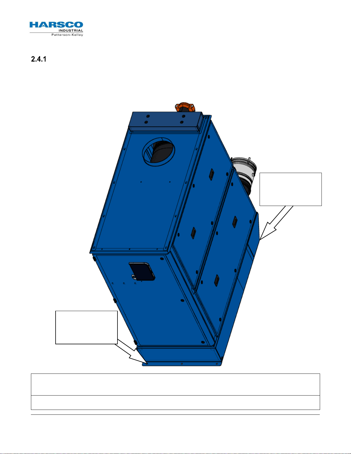
QTY 3: 9/16” Holes
for
Anchor/Lag Bolts
(REAR)
QTY 3: 9/16” Holes
for
Anchor/Lag Bolts
(FRONT)
2.4 Location Setup
Foundation
Provide a firm, level foundation, preferably made of concrete. The P-K SONIC® boilers must be level
and upright to function properly. There are s
1/2" anchor bolts. Once the boiler is installed on the foundation and furnished with anchor/lag bolts,
use a bubble level and adjust the anchor nuts until the appliance is secure and level.
ix 9/16” holes in the base which may be used for 3/8” or
P-K SONIC® Gas Fired Boiler
Technical Service 1.877.728.5351
Revised: June 2, 2017
Released: June 2, 2017
HARSCO Industrial, Patterson-Kelley 2017
All Rights Reserved.
1004905978 P-K SONIC NURO Installation and
Owners Manual (Rev F Jun-2017).docx
Page 5
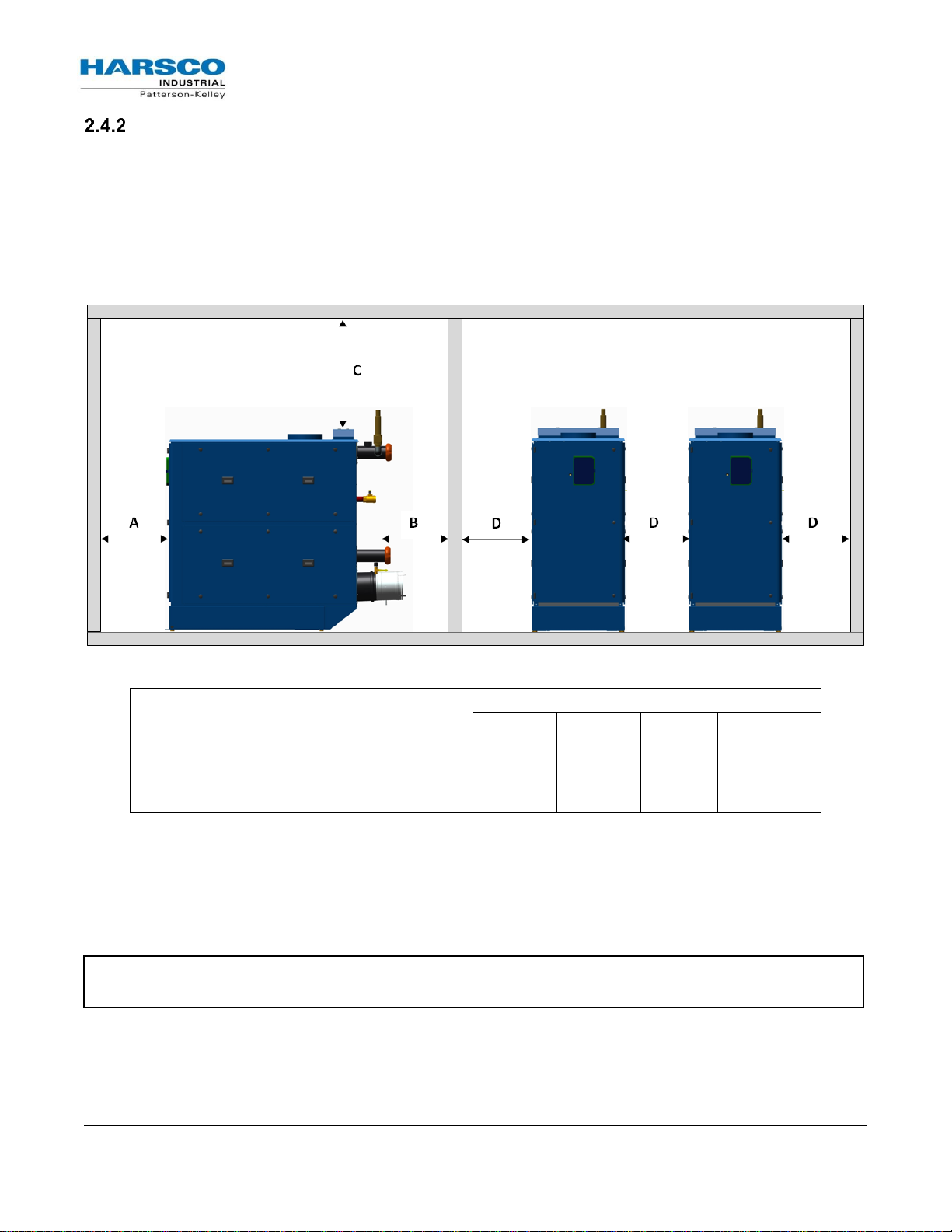
Type of Surface
Dimensions (inches)
A B C†
D
CSA Minimum Clearances to Combustibles
18
6*
12†
6**
Clearance to Non-Combustible Surfaces
0 0 0
0
Recommended Service Clearances
32
12*
12†
12**
Note: Failure to provide recommended service clearances may make it difficult to perform service
on the boiler(s).
Clearances
If the boiler is to be installed near combustible surfaces, the minimum clearances are shown in the
illustration below. Failure to provide adequate service clearances, even with non-combustible surfaces,
may present problems during routine maintenance of the boiler. Maintain a clearance from the vent to
combustible surfaces of 24” or as specified in the vent manufacturer’s listed installation instructions.
The boiler must be installed in a space large in comparison to the boiler as described in the National
Fuel Gas Code, NFPA 54/ANSI Z223.1, Latest Edition.
* “B” Clearance depends upon exhaust vent configuration.
† “C” Space required for pipes, ducts, etc. in this area above the boiler.
** Do not put pipes, ducts, vents, etc. in this space. Electrical conduit must be installed vertically so that
the side doors can be opened.
P-K SONIC® Gas Fired Boiler
Technical Service 1.877.728.5351
Revised: June 2, 2017
Released: June 2, 2017
HARSCO Industrial, Patterson-Kelley 2017
All Rights Reserved.
1004905978 P-K SONIC NURO Installation and
Owners Manual (Rev F Jun-2017).docx
Page 6
Design and installation of
venting systems should be
done only by qualified and
knowledgeable venting systems
personnel and in accordance
with vent system
manufacturer’s installation
instructions. Installing a boiler
or vent system using improper
installation methods or
materials can result in serious
injury or death due to fire or
asphyxiation.
Before connecting a boiler to a
venting system, it must be
determined whether the boiler
is to be installed in a
conventional or direct vent
configuration. In the US,
provisions for combustion air
must be in accordance with
NFPA 54/ANSI Z223.1, National
Fuel Gas Code, latest edition, or
applicable provisions of local
building codes. In Canada,
combustion and ventilation air
openings shall comply with
CAN/CSA B-149.1 Natural Gas
and Propane Installation Code.
For correct installation of a vent
system, read all of these
instructions and refer to the
vent manufacturer’s
instructions.
Failure to use a proper vent
system (types and materials), as
described in this manual will
void the boiler warranty and
may result in rapid deterioration
of the venting system, creating
a health or life safety hazard.
Faulty vent installation can
allow toxic fumes to be released
into living areas. This may
cause property damage, injury,
or death.
NBIC – Part I
National Board Inspection Code Installation
NFPA 54/ANSI Z223.1
National Fuel Gas Code
NFPA/ANSI 211
Chimneys, Fireplaces, Vents and Solid
Fuel Burning Appliances
CAN/CSA B149.1
Installation Codes for Gas Burning
Equipment
UL 441 / ULC S605
Standard for Gas Vents
UL 1738
Venting Systems for Gas-Burning
Appliances, Categories II, III and IV
ULC S636-95
Standard for Type BH Venting System
Sheet Metal and Thermoplastic Duct
Construction Manual Air Conditioning
Contractors National Association
(SMACNA)
2.5
Inlet Air and Exhaust Venting Considerations
Applicable Codes and Standards
United States Installation Codes:
Canada Installation Codes:
Flue Gas Exhaust Vent Standards:
These codes and standards contain information for the venting of
gas fired appliances, including, but not limited to vent sizing,
location, clearance to combustibles, and safe installation practices.
The installation must comply with both the above Federal Codes
and with state, provincial, and local codes.
Combustion Air Inlet Planning (United States and
Canada Considerations)
Air inlet requirements for the U.S. are established by NFPA
54/ANSI Z223.1 & NFPA/ANSI 211.
Air inlet requirements for Canada are established by
CAN/CSA B149.1.
Refer to see section 3.4, for more details on combustion air inlet
requirements in the United States and Canada.
P-K SONIC® Gas Fired Boiler
Technical Service 1.877.728.5351
Revised: June 2, 2017
Released: June 2, 2017
HARSCO Industrial, Patterson-Kelley 2017
All Rights Reserved.
1004905978 P-K SONIC NURO Installation and
Owners Manual (Rev F Jun-2017).docx
Page 7
NOTE: For Category II installations, ensure the flue venting system is designed to maintain a
slightly negative exhaust pressure between -0.01” W.C. and -0.05” W.C.
NOTE: For Category IV installations, ensure the flue venting system is designed to maintain a
slightly positive exhaust pressure which MUST BE in the following ranges:
+0.01” W.C. and +0.22” W.C. (Direct Vent / Sealed Combustion)
+0.01” W.C. and +0.4” W.C. (Exhaust Only)
P-K SONIC® Boiler Model
Draft
Stack Temperature
CO2
Natural Gas
CO2
Propane Gas
SC-1500, SC-2000,
SC-3000, SC-4000
Category II
-0.01” to -0.05” W.C.
220 °F (gross)
9.2%
10.4%
SC-1500, SC-2000,
SC-3000, SC-4000
Category IV
(Sealed Combustion)
+0.01” to +0.22” W.C.
220 °F (gross)
9.2%
10.4%
SC-1500, SC-2000,
SC-3000, SC-4000
Category IV
(Exhaust Only)
+0.01” to +0.4” W.C.
220 °F (gross)
9.2%
10.4%
Category II/IV Flue Gas Exhaust Vent Planning
Several codes and standards have categorized appliances in accordance with the flue gas temperature
and pressure produced by the appliance. The applicable categories are defined as follows:
Category II: An appliance that operates with a non-positive vent static pressure and with a vent
temperature that may cause excessive condensate production in the vent.
Category IV: An appliance that operates with a positive vent static pressure and with a vent
temperature that may cause excessive condensate production in the vent.
Direct Vent: An appliance that is constructed and installed so that all air for combustion is
derived directly from outdoors and all flue gases are discharged to the outdoors.
All P-K SONIC® boilers are dual-certified as Category II or IV appliances, as defined in ANSI
Z21.13/CSA 4.9, latest edition. The P-K SONIC® series boilers are capable of operating with slightly
negative to slightly positive exhaust pressure. It is critical to ensure the flue vent material is certified for
Category II or IV operation.
The vent material to be used for US and Canada is listed in the Table of Acceptable Materials for
Venting Systems located in 2.5.4.
Vent installations shall be in accordance with NFPA 54/ANSI Z223.1, the National Fuel Gas Code, or
CAN/
CSA-B149.1, the Natural Gas and Propane Installation Code, or applicable provisions of the local
building codes.
Vent Sizing for Category II / IV Operation
The vent must be sized in accordance with the ASHRAE Systems and Equipment handbook (Chapter
30) or according to the vent manufacturer’s recommendations. When using manufactured venting
systems, consult your vent supplier for correct sizing and structural support requirements.
P-K SONIC® Gas Fired Boiler
Technical Service 1.877.728.5351
Revised: June 2, 2017
Released: June 2, 2017
HARSCO Industrial, Patterson-Kelley 2017
All Rights Reserved.
1004905978 P-K SONIC NURO Installation and
Owners Manual (Rev F Jun-2017).docx
Page 8
Model
Country
AL29-4C
316L SS
PVC
CPVC
POLYPROPYLENE
SC-1500
US
Yes
Yes
No
Yes
Note 2
SC-2000
US
Yes
Yes
No
Yes
Note 2
SC-3000
US
Yes
Yes
No
Yes
Note 2
SC-4000
US
Yes
Yes
No
Yes
Note 2
SC-1500
Canada
Yes
Yes
No
Note 1
Note 1
SC-2000
Canada
Yes
Yes
No
Note 1
Note 1
SC-3000
Canada
Yes
Yes
No
Note 1
Note 1
SC-4000
Canada
Yes
Yes
No
Note 1
Note 1
NOTE 1: When this material is used for venting, it must be listed to ULC-S636.
NOTE 2: When this material is used for venting, it must be listed to either UL-
1738 or ULC-S636 (depending on the local requirements). Consult the local
boiler codes for more information.
The venting materials listed are
intended for the venting of gas
burning appliances only. Do
not use these venting materials
for venting liquid or solid fuel
(such as oil, kerosene, wood,
or coal) appliances.
Maintain clearances to
combustibles as listed in the
vent manufacturer’s
installation instructions or as
set forth in the codes and
standards listed in this section.
Do not use these vent pipes for
incinerators of any sort!
This boiler is not certified for
use with PVC venting. Use of
PVC venting may result in vent
failure and possible serious
injury or death.
Venting Materials for Flue/Exhaust Systems
The P-K SONIC boilers are dual certified as a Category II and
Category IV appliances, which vents with a temperature that is likely to
cause condensation in the vent. Therefore, any venting system used
with the P-K SONIC® boiler must comply with the requirements for
either Category II or Category IV venting systems as specified in th e
latest edition of NFPA 54/ANSI Z223.1 in the US or th e latest edition of
CAN/CSA B-149.1 in Canada.
CPVC Venting
US: CPVC pipe conforming to ASTM F441. Sch. 80 fittings
conforming to ASTM F439. Joints are to be sealed with
solvent conforming ASTM 493.
Canada: CPVC Pipe, Fitting and Sealant listed and
labeled to ULC S-636 Standard for Type BH Venting
Systems.
Polypropylene Venting
US and Canada: Polypropylene such as InnoFlue® from
Centrotherm or PolyPro® from DuraVent or other listed
manufacturers. When used, the same manufacturer's
material must be used throughout the system. It is not
permissible to use material from different manufacturers
within the same system.
As per ANSI Z21.13b-2012 * CSA 4.9b-2012:
The use of cellular core PVC, CPVC, and Radel® as venting materials is prohibited.
The use of external insulation on plastic vent pipe is prohibited.
Acceptable Venting Materials
P-K SONIC® Gas Fired Boiler
Technical Service 1.877.728.5351
Revised: June 2, 2017
Released: June 2, 2017
HARSCO Industrial, Patterson-Kelley 2017
All Rights Reserved.
1004905978 P-K SONIC NURO Installation and
Owners Manual (Rev F Jun-2017).docx
Page 9
The boiler vent should not be
connected into any portion of
another mechanical draft system
without consulting the vent
manufacturer. The boiler shall
not be connected to any part of
a vent system serving a
Category I appliance, nor shall a
Category I appliance be
connected to any part of the
vent system serving this
appliance. For Category II
common venting, refer to local
venting codes. Improper
interconnection of venting
systems may result in leakage of
flue gases into occupied spaces.
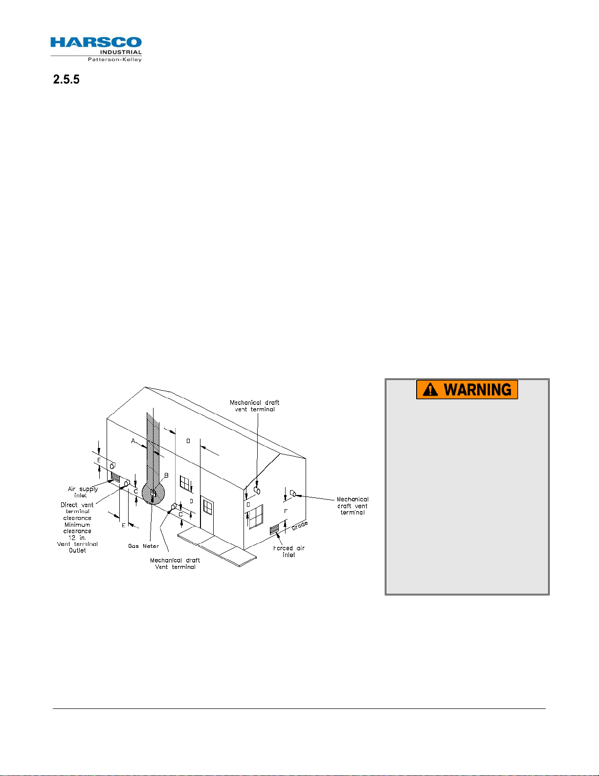
Required Clearances
Conventional Vent Systems Clearances
The following termination clearance requirements are for conventional non direct vent installations:
The vent system shall terminate at least 3 ft. above a forced air inlet located within 10 ft.
horizontally.
The vent system shall terminate at least 4 ft. below, 4 ft. horizontally from, or 1 ft. above any
door, operable window or gravity inlet into any building. The bottom of the vent terminal shall be
at least 12 in. above grade or highest expected snow line (if applicable).
Through the wall terminations shall not terminate over public walkways or over an area where
condensate or vapor could create a nuisance or hazard or could be detrimental to the operation
of regulators, relief valves, or other equipment.
Direct Vent (Sealed Combustion) Systems Clearances
The vent terminal shall be located at least 12 in. from any air opening into a building. The
bottom of the vent terminal shall be at least 12 in. above grade. Both the vent and air intake
terminals must be at least 12 in. above the highest expected snow line.
Through the wall terminations shall not terminate over public walkways or over an area where
condensate or vapor could create a nuisance or hazard or could be detrimental to the operation
of regulators, relief valves, or other equipment.
When multiple direct vent appliances are adjacent, the exhaust must terminate at least 10 ft.
horizontally or 3 ft. vertically from the air intake of another appliance.
P-K SONIC® Gas Fired Boiler
Technical Service 1.877.728.5351
Revised: June 2, 2017
Released: June 2, 2017
HARSCO Industrial, Patterson-Kelley 2017
All Rights Reserved.
1004905978 P-K SONIC NURO Installation and
Owners Manual (Rev F Jun-2017).docx
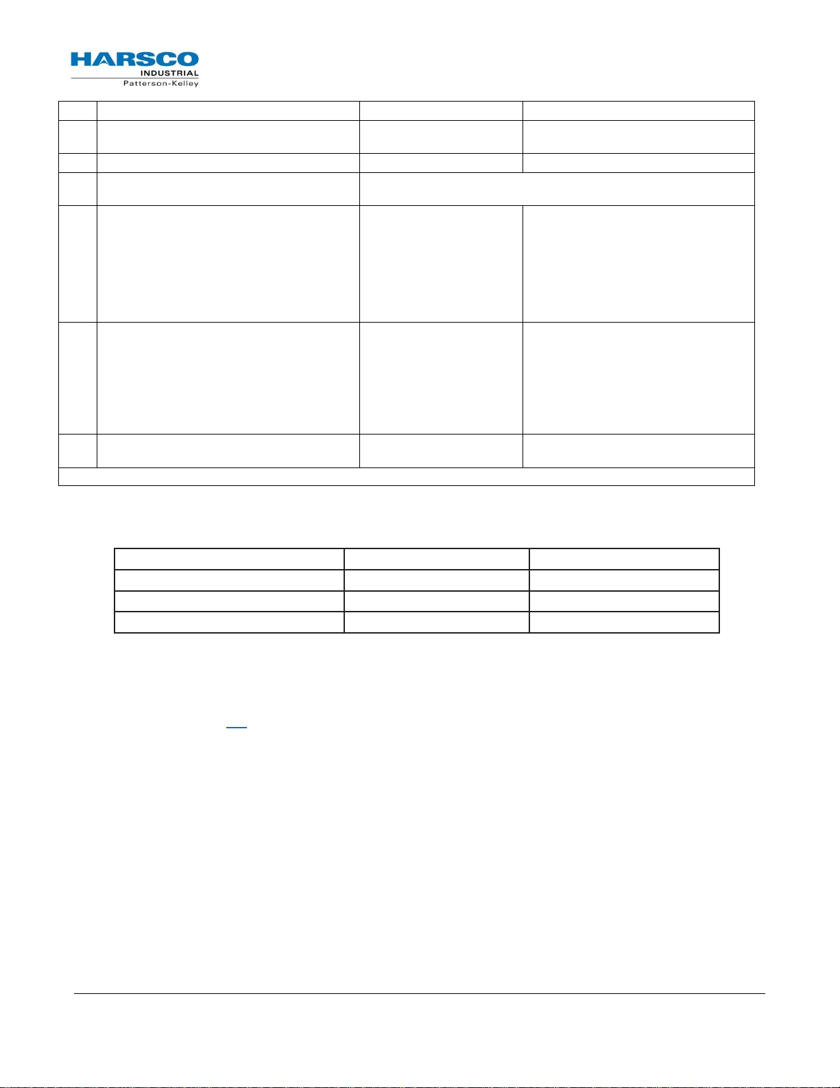
Page 10
Mark
Description
US Installations
Canadian Installations
A
Clearance to each side of center line
extended above meter/regulator
3 ft. (91 cm) within a height of 15 ft. (4.6
m) above the meter/regulator assembly
B
Clearance to service regulator vent outlet
3 ft. (91 cm)
C
Clearance above grade, porch, deck,
veranda, or balcony
12 in
D
Clearance to window or door that may be
opened
4 ft. (1.2 m) below or to side
of opening
1 ft. (300 mm) above
opening
6 in (15 cm) for appliances ≤ 10,000
Btuh (3 kW)
12 in (30 cm) for appliances > 10,000
Btuh (3 kW) and ≤ 100,000 Btuh (30
kW)
36 in (91 cm) for appliances > 100,000
Btuh (30 kW)
E
Clearance to non-mechanical air supply inlet
to building or the combustion air inlet to any
other appliance
4 ft. (1.2 m) below or to side
of opening
1 ft. (300 mm) above
opening
6 in (15 cm) for appliances ≤ 10,000
Btuh (3 kW)
12 in (30 cm) for appliances > 10,000
Btuh (3 kW) and ≤ 100,000 Btuh (30
kW)
36 in (91 cm) for appliances > 100,000
Btuh (30 kW)
F
Clearance to a mechanical air supply inlet
3 ft. (91 cm) above if within
10 ft. (3 m) horizontally
6 feet (1.83 m)
For clearances not specified maintain clearance in accordance with local installation codes and the requirements of the gas supplier
Material
Combustible
Non-Combustibles
Unlisted single wall metal pipe
Do NOT Use
Do NOT Use
Single wall PVC pipe
Do NOT Use
Do NOT Use
UL 1738 listed Category IV vent
Per manufacturer’s listing
Per manufacturer’s listing
Interior Component Clearances
All vent system components shall be installed so as to maintain the following minimum clearances:
Flue Connection
The connection from the appliance to the vent should be as direct as possible and the upward slope of
any horizontal breaching should be at least 1/4 inch per linear foot. Examples of the complete exhaust
system with drain is in 3.5. The appliance connector should incorporate provisions to drain condensate
formed in the vent system. The connector should include an appropriate drain section (not provided).
P-K SONIC® Gas Fired Boiler
Technical Service 1.877.728.5351
Revised: June 2, 2017
Released: June 2, 2017
HARSCO Industrial, Patterson-Kelley 2017
All Rights Reserved.
1004905978 P-K SONIC NURO Installation and
Owners Manual (Rev F Jun-2017).docx
Page 11
Supplying a fuel other than that shown on the appliance’s
nameplate can lead to over firing of the appliance. This can
cause damage to the equipment which could result in serious
injury and/or death.
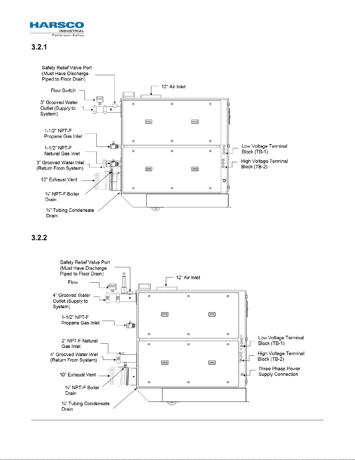
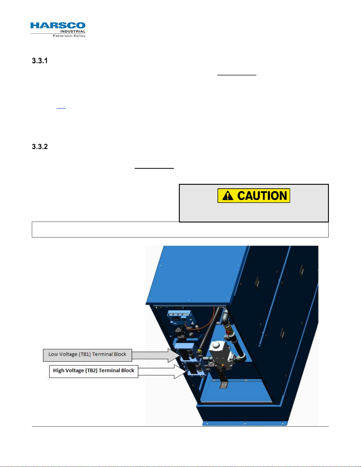
Boiler Model
SC-1500 & SC-2000
SC-3000 & SC-4000
Power Requirement
208-240/1/60 VAC
208-240/3/60 VAC -or-
440-480/3/60 VAC
Air Intake Connection
12”
Nominal Exhaust Vent
Connection
10”
Condensate Drain
3/4" Flexible Tubing
Heat Exchanger Drain
3/4" NPT-F
Natural Gas Shutoff Valve
1-1/2” NPT-F
2” NPT-F
Propane Gas Shutoff Valve
1-1/2” NPT-F
1-1/2” NPT-F
HWR Connection
3” Grooved (Stainless Steel)
4” Grooved (Stainless Steel)
HWS Connection
3” Grooved (Stainless Steel)
4” Grooved (Stainless Steel)
NOTE: Failure to maintain the water quality according to the requirements of the multi-metal
systems water quality standards can void the heat exchanger warranty.
2.6 Gas Piping Considerations
Before making the gas hook-up, make sure the boiler is being supplied with the type of fuel shown on
the boiler nameplate.
The boiler shall be installed such that gas ignition system components are protected from water
(dripping, spraying, rain, etc.) during appliance operation and service (circulator replacement, control
adjustment, etc.).
2.7 Water Quality Standard
The P-K SONIC® boiler’s heat exchanger is made of stainless steel. The heat exchanger requires
proper water conditions to remain efficient and function properly. For more information, refer to Harsco
Industrial, Patterson-Kelley’s Water Quality Standards for Hydronic Boilers in Multi-Metal Systems in
Appendix C – Water Quality Standards Quality Standards for Hydronic Boilers in Multi-Metal
Systems, as this applies to the warranty of your heat exchanger.
3 Installation
3.1 Overview
For site preparation follow the guidelines established in Section 2. Section 3 details the installation
requirements for electrical connections, combustion air, and flue vent piping, hydronic piping, etc.
3.2 Appliance Connections
The table below summarizes the appliance connections to the P-K SONIC® series boilers:
P-K SONIC® Gas Fired Boiler
Technical Service 1.877.728.5351
Revised: June 2, 2017
Released: June 2, 2017
HARSCO Industrial, Patterson-Kelley 2017
All Rights Reserved.
1004905978 P-K SONIC NURO Installation and
Owners Manual (Rev F Jun-2017).docx
Page 12
Appliance Connections (SC-1500 & SC-2000)
All connections must be in compliance with national, state, and local code requirements.
Appliance Connections (SC-3000 & SC-4000)
All connections must be in compliance with national, state, and local code requirements.
P-K SONIC® Gas Fired Boiler
Technical Service 1.877.728.5351
Revised: June 2, 2017
Released: June 2, 2017
HARSCO Industrial, Patterson-Kelley 2017
All Rights Reserved.
1004905978 P-K SONIC NURO Installation and
Owners Manual (Rev F Jun-2017).docx
Page 13
TB2 Terminal 1 = HOT L1
TB2 Terminal 2 = HOT L2
TB2 Terminal 3 = NEUTRAL
TB2 Terminal 4 = GROUND
Do not over-tighten the terminal screws.
Maximum tightening torque = 6 in-lbs!
NOTE: These terminals can accommodate maximum 10 AWG wire.
3.3 Electrical Connections
Power Requirements (SC-1500 & SC-2000)
The SC-1500 and SC-2000 boiler models require 208-240 VAC, single phase, 60 hertz electrical
service. The MCA and MOCP are indicated on the boiler’s rating nameplate. Before starting the boiler,
check to ensure that the proper electrical service is connected to the boiler.
An external electrical disconnect and overload protection (not supplied with the boiler) are required.
Refer to 7.1 for proper wiring and configuration of the electrical connections. The electrical service to
the boiler must be installed and grounded in accordance with local codes or in the absence of such
requirements, in the U.S. with National Electrical Codes, ANSI/NFPA No. 70 latest edition or, in
Canada, to the current Canadian Electrical Code, Part I, CSA C22.1 latest edition. Installed conduit
must not block any of the boiler’s openings and must allow the front door to be opened.
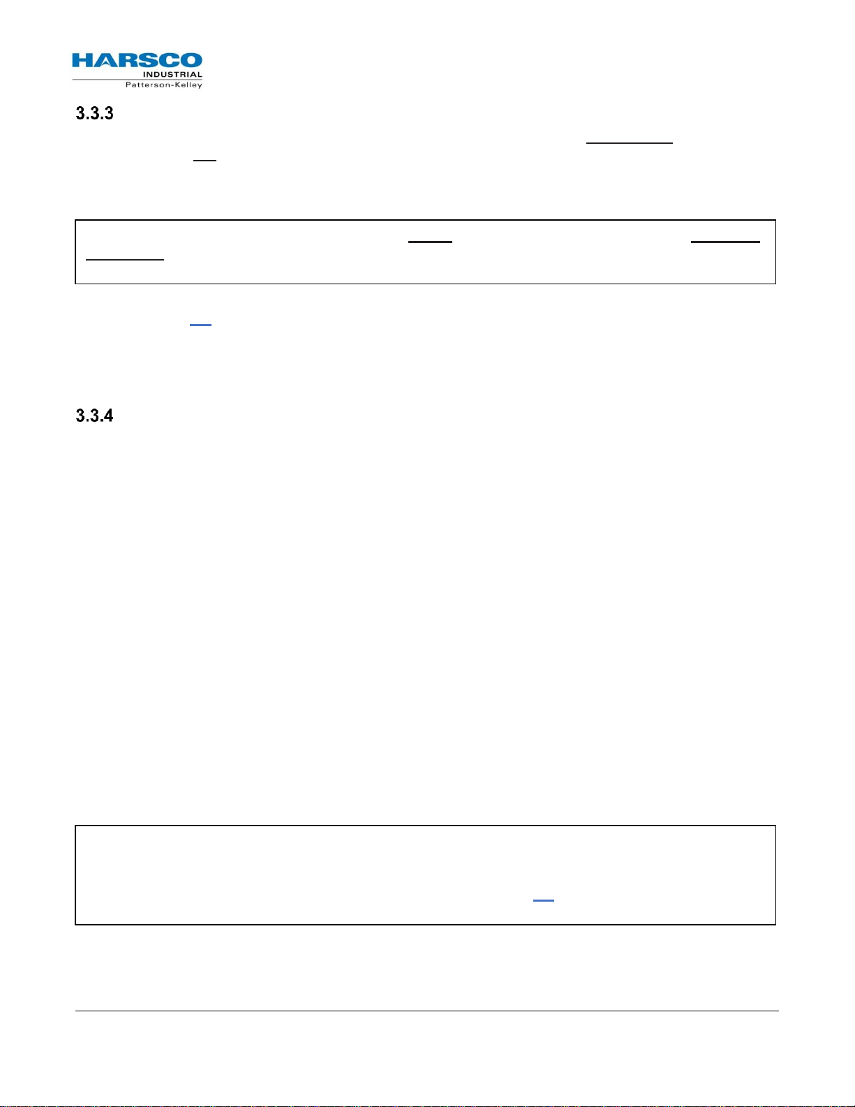
Single Phase Power Supply Connection (SC-1500 & SC-2000)
The SC-1500 and SC-2000 models feature four dedicated power terminals on the High Voltage (TB2)
terminal block for the 208-240VAC, single phase, and 60 hertz electrical supply. The image below
shows the location of the Low Voltage (TB1) and High Voltage (TB2) terminal blocks with the front
door hidden for clarity:
P-K SONIC® Gas Fired Boiler
Technical Service 1.877.728.5351
Revised: June 2, 2017
Released: June 2, 2017
HARSCO Industrial, Patterson-Kelley 2017
All Rights Reserved.
1004905978 P-K SONIC NURO Installation and
Owners Manual (Rev F Jun-2017).docx
Page 14
NOTE: The SC-3000 & SC-4000 boiler models MUST be ordered to the correct voltage! IT IS NOT
POSSIBLE to convert an SC-3000 or SC-4000 between the 240V and 480V configurations in the
field!
NOTICE: If 208 VAC three phase power is supplied to the boiler, the internal control transformer
must be re-wired for operation at this lower voltage. The wire in terminal X3 on the load side of the
internal control transformer must be moved to terminal X4. This supplies 110 VAC power to the
NURO® control from the 208 VAC main voltage. Refer to Section 7.1, for proper wiring and
configuration of the internal control transformer.
Power Requirements (SC-3000 & SC-4000)
The SC-3000 and SC-4000 boilers can be manufactured for 208-240 VAC, three phase, 60 hertz
electrical service OR 440-480VAC, three phase, 60 hertz electrical service. The total operating
amperage is indicated on the rating nameplate and the SC-3000 & SC-4000 boiler models require less
than 20 Amps at full load. Before starting the boiler, check to ensure that the proper electrical service is
connected to the boiler.
An external electrical disconnect and overload protection (not supplied with the boiler) are required.
Refer to Section 7.1, for proper wiring and configuration of the electrical connections. The electrical
service to the boiler must be installed and grounded in accordance with local codes or in the absence of
such requirements, in the U.S. with National Electrical Codes, ANSI/NFPA No. 70 latest edition or, in
Canada, to the current Canadian Electrical Code, Part I, CSA C22.1 latest edition. Installed conduit
must not block any of the boiler’s openings and must allow the front door to be opened.
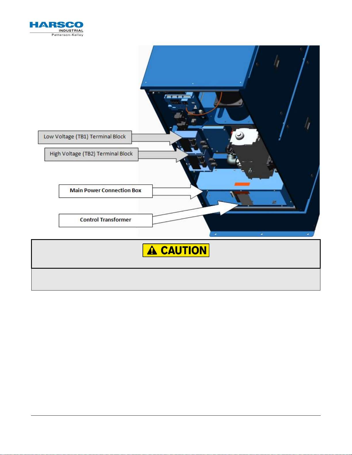
Three Phase Power Supply Connection (SC-3000 & SC-4000)
Main Power Connection Box
Always check the rating nameplate of the SC-3000 or SC-4000 boiler to determine the required
electrical service:
208-240VAC, three phase, 60 hertz
440-480VAC, three phase, 60 hertz
The incoming three phase power for the SC-3000 & SC-4000 boilers is connected to the over-current
safety device (rated for 20 Amps) and the Ground terminal located in the main power connection box.
The image on the next page shows the Low Voltage (TB1) and High Voltage (TB2) terminal blocks,
plus the Main Power Connection Box on the SC-3000 & SC-4000 with the front door hidden for
clarity:
Terminal 1 = HOT L1
Terminal 3 = HOT L2
Terminal 5 = HOT L3
Terminal G = GROUND
Control Transformer
The Main Power Connection Box features a Control Transformer which steps down two hot leads
from the incoming three-phase power in order to supply 110-120VAC single phase power to the
NURO® control system. Be aware that SC-3000 & SC-4000 boilers ordered in the 240V configuration,
are pre-wired from the factory for operation with 240 VAC three phase incoming power.
P-K SONIC® Gas Fired Boiler
Technical Service 1.877.728.5351
Revised: June 2, 2017
Released: June 2, 2017
HARSCO Industrial, Patterson-Kelley 2017
All Rights Reserved.
1004905978 P-K SONIC NURO Installation and
Owners Manual (Rev F Jun-2017).docx
Page 15
Do not over-tighten the hot lead terminal screws. Maximum tightening torque = 13 in-lbs!
NOTE: The hot lead terminals can accommodate maximum 12AWG wire. The ground terminal can
accommodate maximum 8AWG wire.
P-K SONIC® Gas Fired Boiler
Technical Service 1.877.728.5351
Revised: June 2, 2017
Released: June 2, 2017
HARSCO Industrial, Patterson-Kelley 2017
All Rights Reserved.
1004905978 P-K SONIC NURO Installation and
Owners Manual (Rev F Jun-2017).docx
Page 16
Be sure to check the
nameplate on the boiler
before connecting the
electrical supply.
NOTICE!
A dedicated earth ground
(green wire) is required to
avoid nuisance shutdowns.
Do not ground through the
conduit!
The high voltage (TB2)
terminal block on the SONIC
SC-1500 and SC-2000 with
NURO controls contains two
hot leads (HOT L1 & HOT L2),
a neutral lead (NEUTRAL) and
a ground lead (GROUND) for
208- 240 VAC, single phase
60Hz electrical supply. This
terminal block (TB2) also
contains dry-contact relays
with a maximum voltage
rating of 240VAC and 1/2 Amp
maximum current capacity.
Incorrect wiring can result in
equipment damage, injury, or
death.
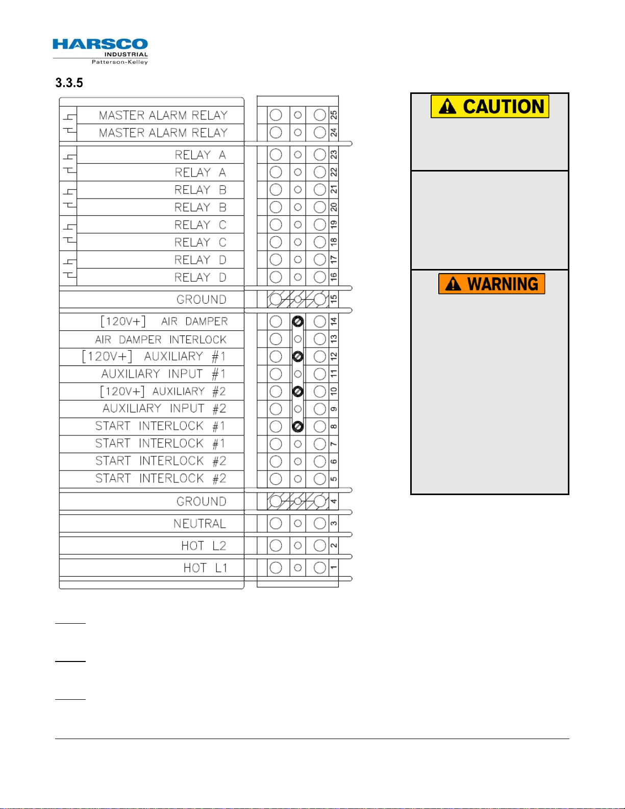
High Voltage (TB2) Terminal Block (SC1500 & SC2000)
TB2-1 terminal.
HOT L2 – Connect the 2nd hot lead of the 208-240VAC, single phase, 60Hz electrical service to the
TB2-2 terminal.
NEUTRAL – Connect the neutral lead of the 208-240VAC, single phase, 60Hz electrical service to the
TB2-3 terminal.
HOT L1 – Connect the 1st hot lead of the 208-240VAC, single phase, 60Hz electrical service to the
P-K SONIC® Gas Fired Boiler
Technical Service 1.877.728.5351
Revised: June 2, 2017
Released: June 2, 2017
HARSCO Industrial, Patterson-Kelley 2017
All Rights Reserved.
1004905978 P-K SONIC NURO Installation and
Owners Manual (Rev F Jun-2017).docx
Page 17
NOTE: The Start Interlock circuit must close within 5 minutes of a call for heat. Failure to close the
Start Interlock circuit will cause the appliance to lockout on alarm.
NOTE:
The boiler ships with a factory-installed jumper across the Air Damper Interlock terminals.
Remove the jumper if connecting a motorized air damper with end limit switch.
NOTE: This ground terminal is connected to the TB2 sheet metal and is not common with the
appliance’s electrical service ground.
NOTE: Refer to 7.1, for proper wiring and configuration of the electrical connections. Relays A
through D can be user-configured through the NURO® touch screen interface to control devices
such as the Comfort Heat (CH) pump, Domestic Hot Water (DHW) Pump, Air Damper, System
Pump, etc.
GROUND – Connect the ground lead from the electrical service to the TB2-4 terminal.
Start Interlock #2 –
The Start Interlock #2 TB2-5 and TB2-6 terminals are in series with Start Interlock
#1 and provide additional connection points for auxiliary safety devices. This circuit is energized with
120VAC, so the contacts on any auxiliary safety devices must be rated for minimum 120VAC.
Start Interlock #1 –
The Start Interlock #1 TB2-7 & TB2-8 terminals can be used for auxiliary safety
devices such as damper limit switches, control valve limit switches, emergency stop buttons, and low
water cutoff devices. This circuit is energized with 120VAC, so the contacts on any auxiliary safety
devices must be rated for a minimum of 120VAC. The appliance ships with a factory-installed jumper
across Start Interlock #1 and Start Interlock #2 terminals. Remove the jumper(s) if using any auxiliary
safety devices.
Auxiliary Input #2 –
energized with 120VAC
Auxiliary Input #1 –
energized with 120VAC
Air Damper Interlock – The Air Damper Interlock TB2-13 & TB2-14 terminals
The TB2-9 & TB2-10 terminals are reserved for future use. This circuit is
.
The TB2-11 & TB2-12 terminals are reserved for future use. This circuit is
.
allow for proof of open
end limit switch on a motorized air damper. This circuit is energized with 120VAC, so the contacts on
the end limit switch must be rated for minimum 120VAC. The appliance ships with a factory-installed
jumper across the Air Damper Interlock terminals. Remove the jumper if connecting a motorized air
damper with end limit switch.
Ground – Grounding connection for auxiliary safety/limit devices on terminal TB2-15.
Relay A, B, C & D – User-configurable relay outputs A (TB2-22 & TB2-23), B (TB2-20 & TB2-21), C
(TB2-18 & TB2-19) & D (TB2-16 & TB2-17). The normally-open contacts on these relays have a
maximum voltage rating of 240VAC and maximum current capacity of 1/2 Amp.
Master Alarm Relay – The Master Alarm Relay TB2-24 & TB2-25 terminals are normally-open dry
contacts that close in the event of an alarm output from the NURO control. The normally-open contacts
on this relay have a maximum voltage rating of 240VAC and maximum current capacity of 1/2 Amp.
P-K SONIC® Gas Fired Boiler
Technical Service 1.877.728.5351
Revised: June 2, 2017
Released: June 2, 2017
HARSCO Industrial, Patterson-Kelley 2017
All Rights Reserved.
1004905978 P-K SONIC NURO Installation and
Owners Manual (Rev F Jun-2017).docx
Page 18
Be sure to check the
nameplate on the boiler
before connecting the
electrical supply.
NOTICE!
A dedicated earth ground
(green wire) is required to
avoid nuisance shutdowns.
Do not ground through the
conduit!
The high voltage (TB2)
terminal block on the SONIC
SC-3000 & SC-4000 with
NURO controls contains dry-
contact relays with a
maximum voltage rating of
240VAC and 1/2 Amp
maximum current capacity.
Incorrect wiring can result in
equipment damage, injury, or
death.
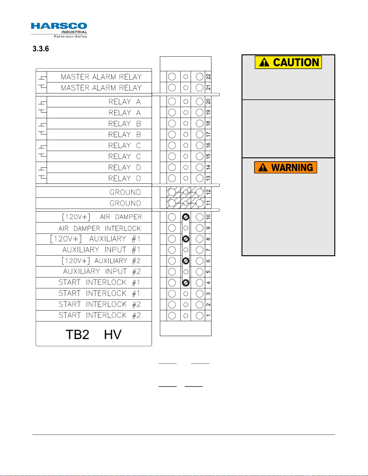
High Voltage (TB2) Terminal Block (SC3000 & SC4000)
Start Interlock #2 –
The Start Interlock #2 TB2-1 and TB2-2 terminals are in series with Start Interlock
#1 and provide additional connection points for auxiliary safety devices. This circuit is energized with
120VAC, so the contacts on any auxiliary safety devices must be rated for minimum 120VAC.
Start Interlock #1 –
The Start Interlock #1 TB2-3 & TB2-4 terminals can be used for auxiliary safety
devices such as damper limit switches, control valve limit switches, emergency stop buttons, and low
water cutoff devices. This circuit is energized with 120VAC, so the contacts on any auxiliary safety
devices must be rated for a minimum of 120VAC. The appliance ships with a factory-installed jumper
across Start Interlock #1 and Start Interlock #2 terminals. Remove the jumper(s) if using any auxiliary
safety devices.
P-K SONIC® Gas Fired Boiler
Technical Service 1.877.728.5351
Revised: June 2, 2017
Released: June 2, 2017
HARSCO Industrial, Patterson-Kelley 2017
All Rights Reserved.
1004905978 P-K SONIC NURO Installation and
Owners Manual (Rev F Jun-2017).docx
Page 19
NOTE: The Start Interlock circuit must close within 5 minutes of a call for heat. Failure to close the
Start Interlock circuit will cause the appliance to lockout on alarm.
NOTE:
The boiler ships with a factory-installed jumper across the Air Damper Interlock terminals.
Remove the jumper if connecting a motorized air damper with end limit switch.
NOTE: This ground terminal is connected to the TB2 sheet metal and is not common with the
appliance’s electrical service ground.
NOTE: Refer to 7.1 for proper wiring and configuration of the electrical connections. Relays A
through D can be user-configured through the NURO® touch screen interface to control devices
such as the Comfort Heat (CH) pump, Domestic Hot Water (DHW) Pump, Air Damper, System
Pump, etc.
Auxiliary Input #2 –
with 120VAC
.
The TB2-5 & TB2-6 terminals are reserved for future use. This circuit is energized
Auxiliary Input #1 –
with 120VAC
.
Air Damper Interlock – The Air Damper Interlock TB2-9 & TB2-10 terminals
The TB2-7 & TB2-8 terminals are reserved for future use. This circuit is energized
allow for proof of open
end limit switch on a motorized air damper. This circuit is energized with 120VAC, so the contacts on
the end limit switch must be rated for minimum 120VAC. The appliance ships with a factory-installed
jumper across the Air Damper Interlock terminals. Remove the jumper if connecting a motorized air
damper with end limit switch.
Ground – Grounding connection for auxiliary safety/limit devices on terminals TB2-11 & TB2-12.
Relay A, B, C & D – User-configurable relay outputs A (TB2-19 & TB2-20), B (TB2-17 & TB2-18), C
(TB2-15 & TB2-16) & D (TB2-13 & TB2-14). The normally-open contacts on these relays have a
maximum voltage rating of 240VAC and maximum current capacity of 1/2 Amp.
Master Alarm Relay – The Master Alarm Relay TB2-21 & TB2-22 terminals are normally-open dry
contacts that close in the event of an alarm output from the NURO control. The normally-open contacts
on this relay have a maximum voltage rating of 240VAC and maximum current capacity of 1/2 Amp.
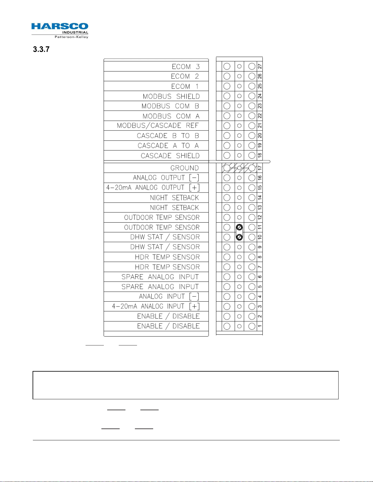
P-K SONIC® Gas Fired Boiler
Technical Service 1.877.728.5351
Revised: June 2, 2017
Released: June 2, 2017
HARSCO Industrial, Patterson-Kelley 2017
All Rights Reserved.
1004905978 P-K SONIC NURO Installation and
Owners Manual (Rev F Jun-2017).docx
Page 20
NOTE: The boiler ships with a factory-installed jumper across the Enable/Disable terminals. This
circuit is energized with a 24VAC potential, so the contacts on any remote enable devices must be
rated for minimum 24VAC.
Low Voltage (TB1) Terminal Block
Enable/Disable –TB1-1 and TB1-2 can be used to remotely enable or disable the boiler. The
functionality of these terminals is user-configurable through the NURO® controls, but generally closure
of the Enable/Disable circuit provides a call for heat to the boiler. Opening this circuit prevents the
boiler from running.
4-20mA Analog Input – TB1-3 and TB1-4 can be used to provide a remote analog 4-20mA control
signal to the boiler. This analog signal can be used to change the boiler’s operating setpoint/firing rate.
Spare Analog Input – TB1-5 and TB1-6 are reserved for future use.
P-K SONIC® Gas Fired Boiler
Technical Service 1.877.728.5351
Revised: June 2, 2017
Released: June 2, 2017
HARSCO Industrial, Patterson-Kelley 2017
All Rights Reserved.
1004905978 P-K SONIC NURO Installation and
Owners Manual (Rev F Jun-2017).docx
Page 21
NOTE: Only ground the Cascade shield wire at the master boiler.
NOTE: Only ground the MODBUS shield wire at the master boiler.
HDR Temp Sensor – TB1-7 and TB1-8 can be used to connect a remote header temperature sensor,
installed in the primary hydronic system piping, downstream of all the boilers. This temperature sensor
must be a 2-wire 12kΩ NTC thermistor. This circuit is energized by the boiler with a 5VDC potential.
DHW Stat/Sensor – TB1-9 and TB1-10 can be used to connect either an aquastat or remote DHW
temperature sensor installed in a domestic hot water storage tank. If using an aquastat, use a SPST
normally-closed, break on rise type with either a fixed or adjustable deadband above and below the
setpoint. Alternatively, if using a temperature sensor, it must be a 2-wire 12kΩ NTC thermistor and be
of sufficient length to measure an accurate storage tank temperature. This circuit is energized by the
boiler with a 5VDC potential.
Outdoor Temp Sensor – TB1-11 and TB1-12 can be used to connect an outdoor air temperature
sensor which allows the NURO control to be programmed to run an outdoor air schedule. The outdoor air
temperature sensor must be a 2-wire 12kΩ NTC thermistor and should be installed on the North face of
the building and shielded from direct sunlight exposure. This circuit is energized by the boiler with a
5VDC potential.
Night Setback – TB1-13 and TB1-14 can be used to connect a day/night or occupancy timer. Closure
of the Night Setback circuit enables the Night Setback mode which reduces the boiler’s operating
setpoint. Opening this circuit resumes normal operation. This circuit is energized by the boiler with a
5VDC potential, so the contacts on the day/night timer must be rated for minimum 5VDC.
4-20mA Analog Output – TB1-15 and TB1-16 provide a 4-20mA analog output signal which tracks the
boiler’s firing rate. When operating at full power (maximum firing rate), the boiler will provide a 20mA
output. When operating at minimum power (minimum firing rate), the boiler will provide a 4mA output.
Ground – TB1-17 provides an equipment (frame) ground connection for input, output, or
communication connections. For independently powered control devices, it may be necessary to
create a common ground.
Cascade Shield & Cascade – TB1-18, TB1-19, and TB1-20 can be used to setup a cascade system
with multiple SONIC boilers with NURO controls. Terminals TB1-19 and TB1-20 are reserved for the
cascade communication between the master and member boilers. Terminal TB1-18 should be used to
connect the cascade communication wiring shield between all boilers. The cascade and shielding must
be wired from the master boiler to each individual member boiler in a daisy-chain fashion.
MODBUS COM & MODBUS Shield – TB1-22, TB1-23, and TB1-24 can be used to integrate the boiler
with a Building Management System (BMS), Protocol Converter, or other device capable of RS-485 2wire MODBUS communication. Terminals TB1-22 and TB1-23 are reserved for MODBUS and terminal
TB1-18 provides a connection for the MODBUS communication wire shield.
ECOM 1, 2 & 3 – TB1-25, TB1-26, and TB1-27 can be used to connect a wireless outdoor air
temperature sensor. The wireless receiver should be installed at or near the boiler, and the wireless
temperature sensor should be installed on the North face of the building and shielded from direct
sunlight exposure.
 Loading...