


&
&
&
&
&
&
&
&
&
Revised Januar y 13, 2015
INSTALLATION
OWNER ’ S
P-K SONIC™ GAS FIRE D BOILER
SC-2000/SC-3000/SC-4000
Natural Gas/Propane/Dual Fuel
Part # 1004 90 59 78
C.S.A Design-Certified
Complies with ANSI Z21.13/CSA 4.9
Gas-Fired Low Pressure Steam and Hot Water Boilers
ASME Code, Section IV
Certified by Patter son-Kelley
M A N
U
A L
INSTALLATION
OWNER ’ S
M A N
U
A L
INSTALLATION
OWNER ’ S
M A N
U
INSTALLATION
OWNER ’ S
M A N
U
INSTALLATION
OWNER ’ S
A L
A L
CERTIFIE D
Model Number:
Serial Number:
Start-Up Date:
Harsco Industrial , Patterson-Kelley
155 Burson Street
East Stroudsburg, PA 18301
Telephone: 570.476.7261
Toll Free: 877.728.5351
Fax: 570.476. 7247
www .harscopk.com
©2015 Harsco Industrial, Patterson-Kelley
Released: 1/13/15
C.S.A Design-Certified
Complies with ANSI Z21.13/CSA 4.9
Gas-Fired Low Pressure Steam and Hot Water Boilers
M A N
U
A L
INSTALLATION
OWNER ’ S
M A N
U
A L
INSTALLATION
OWNER ’ S
M A N
U
A L
INSTALLATION
OWNER ’ S
M A N
U
A L
INSTALLATION
OWNER ’ S
M A N
U
A L

Gaass FFiirreedd BBooiilleerr
Installation and Operation Quick Reference
Fuel/Gas Supply
• Refer to Section 3.6 for information on proper sizing of the gas supply piping. Undersized gas
piping with too much pressure drop will negatively impact the boiler’s performance.
• Install a lock-up type gas regulator to supply an appropriate gas pressure as described below:
Natural Gas Propane Gas
Minimum In let Pressure = 4.0” w.c.
Maximum Inlet P ress ur e = 14.0” w.c.
Minimum In let Pressure = 7.0” w.c.
Maximum Inlet P ress ur e = 14.0” w.c.
• NOTE: Harsco Industrial, Patterson-Kelley recommends installing an individual lock-up type gas
regulator in the gas supply piping to each boiler. For installations where one master lock-up type
gas pressure regulator will service multiple boilers, Patterson-Kelley recommends contacting the
local regulator representative for application assistance specifying the appropriate lock-up type
regulator and gas pipe sizing.
Electrical/Power Supply
• Carefully inspect the boiler’s nameplate labels which describe the power supply requirements.
• Provide an appropriate power feed to the boiler with overcurrent protection:
Boiler Model Power Supply Requirements
SC-2000 (240V)
SC-3000 / SC-4000 (240V)
SC-3000 / SC-4000 (480V)
208-240VAC, single phase, 60Hz sized for 15 Amps.
208-240VAC, three phase, 60Hz sized for 20 Amps.
460-480VAC, three phase, 60Hz sized for 20 Amps.
• NOTE: The SC-3000 & SC-4000 MUST be ordered to the correct voltage! IT IS NOT
POSSIBLE to convert an SC-3000 or SC-4000 between the 240V and 480V configurations in
the field.
• Prior to startup, carefully check all electrical connections for tightness as
connections can come lose during shipping.
Exhaust Venting
• The P-K SONIC boilers are dual-certified as Category II & Category IV appliances,
capable of oper atin g with slightly negative to slightly positive exhaust pressure. It is
critical to ensure the flue venting material is suitable for use with the boiler.
• For Category II installations, ensure the flue venting system is designed to maintain
a slightly negative exhaust pressure which does not exceed -0.04” w.c.
• For Category IV installations, ensure the flue venting system is designed to maintain
a slightly positive exhaust pressure which does not exceed +0.22” w.c.
Harsco Industrial, Patterson-Kelley Technical Service 1.877.728.5351
2

Gaass FFiirreedd BBooiilleerr
Hydronics/Water Flow (SC-2000)
• The chart below represents the pressure drop (Ft of Head) versus the water flow rate (GPM) for
the SONIC SC-20 00. This information is useful to help size an appropriate circulatio n pump.
Keep in mind this pressure drop represents the boiler only, additional consideration is needed for
any connected piping, valves, strainers, couplings, flanges, etc.
• The table below summarizes the minimum and maximum flow restrictions for the SC-2000:
Flow Condition Boiler Operation Flow Rate Approximate ∆T
Maximum Flow High Fire 192 GPM 20°F
Minimum Flow Ignition 48 GPM 20°F
Minimum Flow Low Fire 38 GPM 20°F
Harsco Industrial, Patterson-Kelley Technical Service 1.877.728.5351
3
Gaass FFiirreedd BBooiilleerr
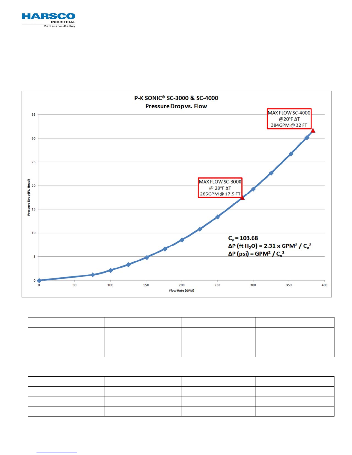
Hydronics/Water Flow (SC-3000 & SC-4000)
• The chart below represents the pressure drop (Ft of Head) versus the water flow rate (GPM) for
the SONIC SC-3000 & SC-4000. This information is useful to help size an appropriate circulation
pump. Keep in mind this pressure drop repres ents the boiler only, additional consideration is
needed for any connected piping, valves, strainers, couplings, flanges, etc.
• The table below summarizes the minimum and maximum flow restrictions for the SC-3000:
Flow Condition Boiler Operation Flow Rate Approximate ∆T
Maximum Flow High Fire 285 GPM 20°F
Minimum Flow Ignition 72 GPM 20°F
Minimum Flow Low Fire 57 GPM 20°F
• The table below summarizes the minimum and maximum flow restrictions for the SC-4000:
Flow Condition Boiler Operation Flow Rate Approximate ∆T
Maximum Flow High Fire 384 GPM 20°F
Minimum Flow Ignition 98 GPM 20°F
Minimum Flow Low Fire 76 GPM 20°F
Harsco Industrial, Patterson-Kelley Technical Service 1.877.728.5351
4

Gaass FFiirreedd BBooiilleerr
Table of Contents
1 Introduction 6
2 Safety 8
2.1 General 8
2.2 Safety Prec autions 8
2.3 Training 9
2.4 Hazard Warnings 9
3 Installation 11
3.1 Receiving and Storage 11
3.2 Compliance with Codes 11
3.3 Setup 12
3.4 Electric al Connec tions 13
3.5 Inlet Air and Exhaust V enting 17
3.6 Gas Piping 27
3.7 Boiler Wat er Piping 28
3.8 Pre-St art Chec kli st 30
3.9 Safety Checks 30
3.10 Initial NURO Control Setup & Adjustment 32
3.11 Fuel/Air A djusment 34
4 Operations 36
4.1 General 36
4.2 Normal Lighting and Shut-down Procedures 37
4.3 Emergency S hut-Of f 37
4.4 Typical Boiler Operating Conditions 37
5 Maintenance 38
5.1 Maintenance and I nspect ions Schedule 38
5.2 Cleaning the Burner & Combustion Chamber 39
5.3 After Repai r s or Maintenance 40
5.4 Sequence of Operat ion 41
5.5 Troubl eshooting 42
6 Parts/Tech Support 44
6.1 Wiring Diagrams 44
6.2 Boiler Part s Identif ication (SC-2000) 55
6.3 Boiler Part s Identif ication (SC-3000 & SC-4000) 59
7 Warranty 65
Boiler Fire-Test Report
66
Appendix 1: Maintenance Log 67
Appendix 2: Boiler Altitude Derate Sch. 68
Appendix 3: Water Quality Standards
Harsco Industrial, Patterson-Kelley Technical Service 1.877.728.5351
69
5

WARNING: If the information
in this manual is not
followed, a fire or explosion
may result causing property
damage, personal injury or
loss of life.
Do not store or use gasoline or
other flammable vapors or
liquids in the vicinity of this or
any other appliance.
Installation and service must be
performed by a qualified
installer, service agency, or the
gas supplier.
WHAT TO DO IF YOU SMELL GAS:
Do not try to light any appliance.
Do not touch any electrical switch;
do not use any phone in your
building.
Immediately call your gas supplier
from a neighbor’s phone. Follow
the gas supplier’s instructions.
If you cannot reach your gas
supplier, call the fire department.
It is essential to read, understand,
and follow the recommendations of
this manual before installing,
operating or servicing this
equipment. Failure to do so could
result in personal injury or death.
Installation and service must be
perform ed by a qu al ified and
knowledgeable individual who has
been certified on the P-K Sonic™
Boiler. The feature s which permit
this boiler to achieve highefficiency performance can be
misused which could result in
personal injury or death.
Gaass FFiirreedd BBooiilleerr
1 INTRODUCTION
This manual describes the installation and operation of the
following
SC-2000:
Natural Gas, 208-240V (single phase)
Propane Gas, 208-240V (single phase)
SC-3000:
Natural Gas, 240V (three phase)
Natural Gas, 480V (three phase)
Propane Gas, 240V (three phase)
Propane Gas, 480V (three phase)
SC-4000:
Natural Gas, 240V (three phase)
Natural Gas, 480V (three phase)
Propane Gas, 240V (three phase)
Propane Gas, 480V (three phase)
If you have any questions on the information contained within,
or do not fully and completely understand the content, please
contact Harsco Industrial, Patterson-Kelley Technical Service at
570.476 .7 26 1 or tol l free at 877. 72 8. 5351.
The
variable speed combustion blowers, sophisticated
microprocessor controls, modulating gas safety shut off/control
valves and a unique stainless steel heat exchanger capable of
operating in a fully condensing mode to provide maximum
efficiency in a minimum amount of space.
While specific details may differ slightly, basic operation is the
same for all models. Check the rating plate for correct fuel
usage and gas pressur es .
The boiler is only a part of the complete heating system. This
boiler may be fully operational and yet because of poor
circulation, control, or other operating characteristics may not
deliver heat to the desired location. Additional equipment such
as temperature sensors, pumps, flow switches, balancing
valves, and check valves will be required for satisfactory
operation of any system. Harsco Industrial, Patterson-Kelley
cannot be responsible for the design or operation of such
systems and a qualified engineer or contractor must be
consulted.
P-K SONIC™ boilers featuring NURO controls:
P-K SONIC™ gas fired boilers are fully modulating using
Harsco Industrial, Patterson-Kelley Technical Service 1.877.728.5351
6

REVISION NOTES:
1/13/2015 – Revised flame signal information.
12/10/14 – Revised to include SC-2000 & NURO controls.
07/8/14 – Edited text, made grammar corrections.
Gaass FFiirreedd BBooiilleerr
Harsco Industrial, Patterson-Kelley Technical Service 1.877.728.5351
7

r
2 S
AFETY
2.1 General
The SC-2 0 00, SC-3000 and SC-4 00 0 gas-fired boilers must be:
• Instal led, operated, and serviced in ac c or danc e with instructions
contained i n this manual and other supplemental manuals.
• Instal led by qualified personnel in accordanc e with designs prepared by
qualified facility engineers includi ng: str uc tural, mechanical, electrical, and
other applicable disciplines.
• Operat ed and serviced in accordance with a comprehensive safety
program det ermined and established by the customer. Do not attempt to
operate or servic e until such a pr ogr am has been established.
• Operat ed and serviced by experienced, qualif ied, and properly trained
personnel in accor danc e with all applicable codes, laws, and regulations.
2.2 Safety Precautions
Provide a suitable location for the boiler, away from normal personnel
traffic, with adequate working space, adequate clearances, proper
ventilation and lighting, with a structure sufficiently strong and rigid to
support the weight of the boiler, all piping, and accessories.
Gas Fired Boile
N
OTICE
Each safety device must be
maintai ne d an d chec ked per the
recommended schedule. Refer to
Section 5. 1 of this manual.
!
Safet y Feat ur es
It is the responsibility of the
customer to ensure external safety
provisions, such as but not limited
to: guards, safety labels, safety
controls, interlocks, lockout devices,
are in place and operable.
Safet y Labe ls
The following words are used in this
manual to denote the degree of
seriousness of the individual
hazards.
Indicates an imminently hazardous
situation which, if not avoided, will
result in death or serious injury. This
signal word is to be limited to the
most extreme situations.
Indicates a potentially hazardous
situation which, if not avoided, coul d
result in death or serious injury.
Indicates a potentially hazardous
situation which, if not avoided, may
result in minor or moderate injury. It
may also be used to alert against
unsafe practices.
Harsco Industrial, Patterson-Kelley Technical Service 1.877.728.5351
8
N
OTICE/NOTE - NOTICE
Is the preferred signal word to
address pr acti ces not rela ted to
personal injury. The safety alert
symbol is not used with this signal
word.
r
Gas Fired Boile
NOTICE!
The safety labels shown below are
affixed to your boi ler. Although the
labels are of high quality, they may
become dis l o dg ed or unr e adable
over time. Contact Harsco
Industrial, Patterson-Kelley at
570. 476.7261 or toll-f r ee at
877.728. 5 35 1 for repl ac ements.
Gas may lose its odor. Proper gas
sensing eq ui pment and pr ocedures
should be used for leak checks.
Failure to detect gas leaks could
result in injury or death.
2.4.4 Press u re Haz a rd s
Pressure Hazard! Hot fl uids. Install isolation valves on boi ler water inlet and outlet. Make sure
isolati on valves are closed before servicing boiler .
Pressure Hazard! Hot fl uids. Annually test safety relief v alve(s) for proper operation. Do not operate
boiler with faulty relief valve(s).
2.3 Traini ng
Proper training is the best protection against accidents. It is
essential to read, understand, and follow the recommendations of
this manual before installing, operating, or servicing this
equi pm en t. Fa il ur e to do s o coul d res ult in fir e or ex pl osi on a nd
serious injury , death, and/or property damage.
Operating and service personnel must be thoroughly familiar with
the basic construction of the SC-2000,
boilers, the use and locations of the controls, the operation of the
boilers, adjustment of their various mechanisms, and all applicable
safety precautions. If any of the provisions of this manual are not
fully and completely understood, contact Harsco Industrial,
Patt er s on- K ell ey Tec hni c al Ser v i ce at
877.728.5351.
2.4 Hazard Warnings
2.4.1 Elect rical Hazard s
Shock Hazard! Properly lockout/tagout the electrical
service and all other energy sources before working on
2.4.2 Crush Hazards
or near the boiler .
Shock Hazard! Do not spray water directly on this
boiler or any electrical components.
Electrical Haz ard! Do not alter wiring connections.
Lifting Hazards! Use properly rated lifting equipm ent
to lift and position the boiler. The load is unbalanced.
Test the balanc e before lifting off the floor. Do not
allow personnel beneath the lifted load. Refer to the
approxim ate weights in the table.
Boiler Model Weight in Pounds
SC-2000 1,450 lbs
SC-3000 1,850 lbs
SC-4000 1,900 lbs
2.4.3 Bump Hazard from Overhead Ductwork and Piping
Injury Hazard ! Install c om ponents with adequate
vertical clearance.
SC-3000 and SC-4000
570.476.7261 or toll free at
Harsco Industrial, Patterson-Kelley Technical Service 1.877.728.5351
9

r
2.4.5 Slip, Fall Hazards
Tripping Hazard! Do not install piping on floor surfaces. Maintai n a clear pat h ar ound the boiler.
Slip and Fall Hazard ! Use a drip pan to catch water while draining the boil er. Maintain dry floor surfaces.
Slip and Fall Hazard ! Do not locate intake or exhaust terminati ons di r ectly above a walkway; dripping of
condensate can cause ic ing of the walking surface. Refer to Section 3.5.
Fall Hazard! Do not stand on boiler.
2.4.6 Chemical Hazards
Chemical Hazard s from Clean in g Product s. Use
caution when cleaning the system. The use of
professional assistanc e is recommended. Use safe
procedures for t he disposal of all cleaning soluti ons.
Combustion Condensate – An acidic pH of
approxim ately 3. 0 to 5.0 can be ex pec t ed. Use PVC, CPVC, or other c or r osi on r esi stant piping for
drainage. Coll ection and disposal must be in accordance with all applicable regulations. A condensate
neutralizati on ki t is available. Please contact your loc al Har sco I ndustr ial, Patterson-Kelley representative
for more i nfor matio n.
2.4.7 Burn, Fire and Explosion H azards
Burn, fire, and ex pl osi on hazar ds! Installation must be in s tric t con fo r mance to a ll applicable codes
standards including NFPA 54, AN SI Z223.1 and CAN/CSA B.1 49. Install all required vent lines for gas
devices. Refer to Section 3.5 .
Hazard from Incorrect Fuels! Possible fire, e xplosion, overheating, and d amage. Do not use any fu e ls
except the design fuels for the unit.
Overfire Hazar ds! H igh pressure in gas s upply could result in o ver firing o f th is or o ther devices supplied
from the same source.
Fire a n d E x plo s i on Ha z ar ds! Clos e the ma in gas s hut o f f before ser vicing boiler.
Fire and Explosion Hazards! Do not store or use gaso line or o ther fla m mab le vapors or liquids in the
vicinity of this or any other gas fired appliance.
Burn hazard! Possible hot sur faces . Do not touch gas vent during firing op era tion. Us e only factory
recommended vent componen ts.
Burn Hazard! Pipes, vents, a nd bo iler co mpon ents could be hot. Do not touch p iping or stack surfa ces
during operation or im med iat e ly afte r shutdown of the boiler.
Burn Hazard! Hot flue! Use caution when ser vicing or d r aining boiler.
Fire and Explosion Hazards! Use caution when ser vicing bur ner. P rop ane ( LP G) is heavier than air and
may linger in the combustion chamber , vent lines, or elsewhere .
Gas Leak Hazard! Make sure the burner is installed correctly and blower/trans ition is securely fastened
following any maintenance perfor med on them. These conne ctions may leak gas if assembled incorrectly.
Gas Leak Hazard! A ll threaded gas connections must be made using a pipe compound that is resistant to
liquefied petro leum gas . Do not use Teflon™ tape on thr eaded g as piping.
Gas Leak Hazard! Check entire gas tra in for leaks after insta llation. If there is a s me ll of gas, sh ut d ow n the
boiler and obtain immediate assistance from trained ser vice personnel and/or your local fire department .
Overfire Hazard! Poss ible fire and explosion from excess gas pressure. Make sure that gas inlet pressure
does not exceed 14 inches w .c.
Overfire Hazard! Possible fire and explosion. Possible malfunction of regulators and/or gas safety shut
off/control valves. Maintain all gas train components in good condition. Do not alter wiring connections.
Annual inspec tion by facto r y-t ra ined pe rs onne l for pr oper set-up and opera t ion is recommended.
Overfire and Underfire Hazards! Poss ible fire, explosio n, overheating, and compon ent failure. Do not
attempt to adjust firing ra te o f the bo iler. The firing rate mus t be adjus ted on ly by fac to ry trained personnel.
Gas Fired Boile
and
Harsco Industrial, Patterson-Kelley Technical Service 1.877.728.5351
10

r
3
I
NSTALLATION
Gas Fired Boile
Installation and service must be
performed by a qualified installer,
service agency, or gas supplier.
Failure to install the equipment in
accordance with this manual could
result in an unsafe operating
condition.
NOTICE!
Controls and other equipment that
are damaged or fail due to weather
exposure are not covered by
warranty.
The wheels provided with this
boiler are for positioning purposes
only. When positioning this boiler,
maintain positive control of it at all
times. Do not attempt to move the
boiler on surfaces that are not
level. Failure to heed this warning
could result in personal injury or
death.
NOTICE!
The boiler may be installed on a
combustible floor; however, the
boiler must never be installed on
carpeting.
Bumping hazard from overhead
ducts! Install all components with
adequate vertical clearances.
Insufficient clearance can restrict
the service access, increasing the
possibility of injury.
3.1 Receiving and Storage
3.1.1 Initial Inspection
Upon receiving the boiler, inspect it for signs of shipping damage.
Some damage may be hidden. Unpack the boiler, open the front
and side doors and inspect the boiler. Verify that the total number
of pieces shown on the packing slip agrees with those actually
received.
3.1.2 Storage Prior t o In s t all at ion
If the boiler is not installed immediately, it must be stored in a
location adequately protected from the weather, preferably indoors.
If this is not possible, then it should remain in the shipping container
and be covered by a tarpaulin or other waterproof covering.
3.2 Compliance with Codes
The boiler with standard components and with many options
complies with American National Standard/CSA Standard ANSI
Z21.13/CSA 4.9, latest edition, Gas-Fired Low Pressure Steam and
Hot Water Boilers.
The SC-2000 heat exchanger is constructed and stamped in
accordance with ASME Boiler and Pressure Vessel Code, Section
IV (160 psig maximum operating pressure).
The SC-3000 and SC-4000 contain two separate heat exchangers
constructed and stamped in accordance with ASME Boiler and
Pressure Vessel Code, Section IV, and Section VIII – Division 1
(160 psig maximum operation pressure).
Installation of the boiler must conform to all the requirements of all
national, state and local codes established by the authorities having
jurisdiction or, in the absence of such requirements, to the National
Fuel Gas Code, ANSI Z223.1/NFPA 54 latest edition in the U.S. In
Canada, the equipment shall be installed in accordance with the
current Installation Code for Gas Burning Appliances and
Equipment, CAN/CSA-B.149, latest edition, and applicable
Provincial Regulations for the class, which should be carefully
followed in all cases. Authorities having jurisdiction should be
consulted before making any installation.
Where required by local codes, the installation must conform to
American Society of Mechanical Engineers Safety Code for
Controls and Safety Devices for Automatically Fired Boilers (ASME
CSD-1).
In the Commonwealth of Massachusetts (a) this unit must be
installed by
cocks must be “T” handle type, (c) piping of condensate shall
conform to the State Plumbing Code, and (d) refer to the
Massachusetts Supplement for further details.
a licensed pipe fitter/plumber, (b) field installed gas
Harsco Industrial, Patterson-Kelley Technical Service 1.877.728.5351
11

r
Gas Fired Boile
3.3 S
etup
3.3.1 Foundation
Provide a firm, level foundation, preferably of concrete. Lifting the front of the boiler slightly will allow the boiler
to be rolled off the shipping skid onto the concrete foundation. Once in position, the wheel bolts may be removed
allowing the wheels to recess up into the boiler. The base will sit flat on the provided foundation. If the boiler is
to be pulled out for maintenance, the wheels may be left attached.
3.3.2 Plac ement
The boiler must be level to function properly. Six 9/16” holes in the base may be used for 3/8” anchor bolts.
3.3.3 Clearances
If the boiler is to be installed near combustible surfaces, the minimum clearances shown in Table 3.3.3 and
Figure 3.3.3. must be maintained. Failure to provide for the service access clearances, even with non-
combustible surfaces, may cause future problems servicing the boiler. Maintain a clearance from the vent to
combustible surfaces of 24” or as specified in the vent manufacturer’s listed installation instructions. The boiler
must be installed in a space large enough in comparison to the boiler as described in the National Fuel Gas
Code, ANSI Z223.1, latest edition.
Table 3.3.3
Type of Surface Dimensions (inches)
Combustible Surfaces Minimum Clearances 30 12* 24† 12**
Recommended Clearances for Service Access
Figure 3.3.3
A B C D
30 12* 24† 12**
* “B” Clearance depends upon exhaust vent configuration.
† “C” Space required for pipes, ducts, etc. in this area above the boiler.
** Do not put pipes, ducts, vents, etc in this space. Electrical conduit must be installed
vertically so that the side doors can be opened.
NOTE: Annual maintenance items can be accessed from the front of the boiler.
Harsco Industrial, Patterson-Kelley Technical Service 1.877.728.5351
12

r
Gas Fired Boile
3.4 Electrical Connections
The SC-2000 boiler requires 208-240 VAC, single phase, 60 hertz electrical service. The total operating amperage
is indicated on the rating nameplate and the SC-2000 requires less than 15 Amps at full load. Before starting
the boiler, check to ensure that the proper electrical service is connected to the boiler.
SC-3000 and SC-4000 boilers can be manufactured for 208-240 VAC, three phase, 60 hertz electrical service
The
440-480VAC, three phase, 60 hertz electrical service. The total operating amperage is indicated on the rating
OR
nameplate and the SC-3000 & SC-4000 boilers require less than 20 Amps at full load. Before starting the boiler,
check to ensure that the proper electrical service is connected to the boiler.
NOTE: The SC-3000 & SC-4000 MUST be ordered to the correct voltage! IT IS NOT POSSIBLE to convert
an SC-3000 or SC-4000 between the 240V and 480V configurations in the field.
An external electrical disconnect (not supplied with the boiler) i s required. Refer to Section 6.1 for proper wiring
and configuration of the electrical connections. The boiler electrical service must be installed and grounded in
accordance with local codes or in the absence of such requirements, in the U.S. with National Electrical Codes,
ANSI/NFPA No. 70 latest edition or, in Canada, to the Canadian Electrical Code, Part I,
Installed conduit must not block any of the boiler’s openings and must allow the side doors to be opened.
3.4.1 Single Phase Power Supply Connection (SC-2000 Only)
High Voltage (TB2) Terminal Block
The SC-2000 must be supplied with 208-240VAC, single phase, 60 hertz electrical service. The SC-2000
features four dedicated power terminals on the High Voltage (TB2) terminal block. Figure 3.4.1 shows the
Low Voltage (TB1) and High Voltage (TB2) terminal blocks on the SC-2000 with the front door hidden for
clarity:
CSA C22.1, latest edition.
TB2 Terminal 1 = HOT L1
TB2 Terminal 2 = HOT L2
TB2 Terminal 3 = NEUTRAL
TB2 Terminal 4 = GROUND
NOTE:Theseterminalscan
accommodatemaximum10AWG
wire.
CAUTION:Donotover‐tighten
theterminalscrews.Maximum
tighteningtorque=6in‐lbs!
LowVoltage(TB1)TerminalBlock
HighVoltage(TB2)TerminalBlock
Figure3.4.1
Harsco Industrial, Patterson-Kelley Technical Service 1.877.728.5351
13

r
3.4.2 Three Phase Power Supply Connection (SC-3000 & SC-4000 Only)
Main Power Connecti on Box
Check the rating nameplate of the SC-3000 or SC-4000 boiler to determine the required electrical service:
208-240VAC, three phase, 60 hertz
440-480VAC, three phase, 60 hertz
The incoming three phase power for the SC-3000 & SC-4000 boilers is connected to the over-current safety
device (rated for 20 Amps) and the Ground terminal located in the main power connection box. Figure 3.4.2
shows the Low Voltage (TB1) and High Voltage (TB2) terminal blocks, plus the Main Power Connection Box
on the SC-3000 & SC-4000 with the front door hidden for clarity:
Terminal 1 = HOT L1
Terminal 3 = HOT L2
Terminal 5 = HOT L3
Terminal G = GROUND
The Main Power Connection Box features a Control Transformer which steps down two hot leads from the
incoming three-phase power in order to supply 110-120VAC single phase power to the boiler’s control system.
Be aware that SC-3000 & SC-4000 boilers ordered in the 240V configuration, are pre-wired from the factory for
operation with 240 VAC three phase incoming power.
If 208 VAC three phase power is supplied to the boiler, the internal control transformer must be re-wired for
operation at this lower voltage. The wire in terminal X3 on the load side of the internal control transformer must
be moved to terminal X4. This supplies the 120 VAC power to the controls from the 208 VAC main voltage.
Refer to Section 6.1.4 for proper wiring and configuration of the internal control transformer.
Gas Fired Boile
NOTE:Thehotleadterminalscan
accommodatemaximum12AWG
wire.Thegroundterminalcan
accommodatemaximum8AWG
wire.
CAUTION:Donotover‐tightenthe
hotleadterminalscrews.Maximum
tighteningtorque=13in‐lbs!
LowVoltage(TB1)TerminalBlock
HighVoltage(TB2)TerminalBlock
MainPowerConnectionBox
ControlTransformer
Harsco Industrial, Patterson-Kelley Technical Service 1.877.728.5351
Figure3.4.2
14

r
Gas Fired Boile
3.4.2 Hi gh Voltage (TB 2) Terminal Blo ck
Be sure to check the nameplate on
the boiler before connecting the
electrical supply.
N
OTICE
!
A dedicated earth ground (green
wire) is required to avoid nuisance
shutdowns. Do not ground through
the conduit!
The high voltage (TB2) terminal
block on the SONIC SC-2000 with
NURO controls contains two hot
leads (
lead (
(
GROUND
HOT L1 & HOT L2
NEUTRAL
) and a ground lead
) for 208- 240 VAC,
), a neutral
single phase 60Hz electrical
supply. This terminal block (TB2)
also contains dry-contact relays
with a maximum voltage rating of
240VAC
and
1/2 Amp
maximum
current capacity. Incorrect wiring
can result in equipment damage,
injury or death.
The high voltage (TB2) terminal
block on the SONIC SC-3000 &
SC-4000 with NURO controls
contains dry-contact relays with a
maximum voltage rating of
and
1/2 Amp
maximum current
240VAC
capacity. Incorrect wiring can
result in equipment damage, injury
or death.
Start Inter lock #1 – The Start Interlock #1 terminals can be used
for auxiliary safety devices such as damper end limit switches,
control valve end limit switches, emergency stop buttons, and low
water cutoff devices. This circuit is energized with
120VAC
contacts on any auxiliary safety devices must be rated for a
minimum of
120VAC
.
Start Inter lock #2 – The Start Interlock #2 terminals are in series
with Start Interlock #1 and provide additional connection points for
auxiliary safety devices. This circuit is energized with
120VAC
the contacts on any auxiliary safety devices must be rated for
minimum
120VAC
.
The boiler ships with a factory-installed jumper across Start
Interlock #1 and Start Interlock #2 terminals. Remove the
jumper(s) if using any auxiliary safety devices.
NOTE: Both the Start Interlock #1 and Start Interlock #2 circuits
must close within 5 minutes of a call for heat. Failure to close
the Start Interlock circuit will cause the boiler to lockout on
alarm.
Auxiliary Input #1 – These terminals are reserved for future use.
This circuit is energized with
120VAC
.
Auxiliary Input #2 – These terminals are reserved for future use.
This circuit is energized with
120VAC
.
Air Damper Interlock – The Air Damper Interlock provides
dedicated terminals for proof of open end limit switch on a
motorized air damper. This circuit is energized with
120VAC
contacts on the end limit switch must be rated for minimum
The boiler ships with a factory-installed jumper across the Air
Damper Interlock terminals. Remove the jumper if connecting
a motorized air damper with end limit switch.
Relay A – User-configurable relay output #1. The normally-open
contacts on this relay have a maximum voltage rating of
and maximum current capacity of
Relay B – User-configurable relay output #2. The normally-open
1/2 Amp
.
contacts on this relay have a maximum voltage rating of
and maximum current capacity of
Relay C –
User-configurable relay output #3. The normally-open
1/2 Amp
.
contacts on this relay have a maximum voltage rating of
and maximum current capacity of
1/2 Amp
.
, so the
, so
, so the
120VAC
240VAC
240VAC
240VAC
.
Relay D –
rating of
User-configurable relay output #4. The normally-open contacts on this relay have a maximum voltage
240VAC
and maximum current capacity of
NOTE: Relays A thru D can be user-configured through the NURO touch screen interface to control devices
such the Comfort Heat (CH) Pump, Domestic Hot Water (DHW) Pump, Air Damper, System Pump, etc.
Mast er A l arm Rel ay – The Master Alarm Relay terminals are normally-open dry contacts that close in the event
of an alarm output from the boiler control.
Refer to Section 6.1 for proper wiring and configuration of the electrical connections.
Harsco Industrial, Patterson-Kelley Technical Service 1.877.728.5351
1/2 Amp
15
.

r
3.4.3 Low V o lt age (TB 1) Term in al Blo ck
Gas Fired Boile
Enable/Disable –
TB1-1 and TB1-2 can be used to remotely enable or disable the boiler. The functionality of
these terminals is user-configurable through the NURO controls, but generally closure of the Enable/Disable
circuit provides a call for heat to the boiler. Opening this circuit prevents the boiler from running.
The boiler ships with a factory-installed jumper across the Enable/Disable terminals. This circuit is energized
with a
4-20mA Analog Input –
24VAC potential, so the contacts on any remote enable devices must be rated for minimum 24VAC.
TB1-3 and TB1-4 can be used to provide a remote analog 4-20mA control signal to the
boiler. This analog signal can be used to change the boiler’s operating setpoint or firing rate.
Spare Analog Input –
TB1-5 and TB1-6 are reserved for future use.
HDR Temp Sensor – TB1-7 and TB1-8 can be used to connect a remote header temperature sensor, installed
in the primary hydronic system piping, downstream of all the boilers. This temperature sensor must be a 2-wire
12kΩ NTC thermistor. This circuit is energized by the boiler with a
DHW Stat/Sensor –
TB1-9 and TB1-10 can be used to connect either an aquastat or remote DHW temperature
5VDC potential.
sensor installed in a domestic hot water storage tank. If using an aquastat, use a SPST normally-closed, break
on rise type with either a fixed or adjustable deadband above and below the setpoint.
Alternatively, if using a temperature sensor, it must be a 2-wire 12kΩ NTC thermistor and be of sufficient length
to measure an accurate storage tank temperature. This circuit is energized by the boiler with a
Outdoor Temp Sensor –
TB1-11 and TB1-12 can be used to connect an outdoor air temperature sensor which
5VDC potential.
allows the NURO control to be programmed to run an outdoor air schedule. The outdoor air temperature sensor
must be a 2-wire 12kΩ NTC thermistor and should be installed on the North face of the building and shielded
from direct sunlight exposure. This circuit is energized by the boiler with a
5VDC potential.
Night Setback –
TB1-13 and TB1-14 can be used to connect a day/night or occupancy timer. Closure of the
Night Setback circuit enables the Night Setback mode which reduces the boiler’s operating setpoint. Opening
this circuit resumes normal operation. This circuit is energized by the boiler with a
on the day/night timer must be rated for minimum
4-20mA Analog Output –
TB1-15 and TB1-16 provide a 4-20mA analog output signal which tracks the boiler’s
5VDC.
5VDC potential, so the contacts
firing rate. When operating at full power (maximum firing rate), the boiler will provide a 20mA output. When
operating at mimimum power (minimum firing rate), the boiler will provide a 4mA output.
Ground –
TB1-17 provides an equipment (frame) ground connection for input, output, or communication
connections. For independently powered control devices, it may be necessary to create a common ground.
Cascade Shield & Cascade –
TB1-18, TB1-19 and TB1-20 can be used to setup a cascade system with multiple
SONIC boilers with NURO controls. Terminals TB1-19 and TB1-20 are reserved for the cascade communication
between the master and member boilers. Terminal TB1-18 should be used to connect the cascade
communication wiring shield between all boilers. The cascade and shielding must be wired from the master
boiler to each individual member boiler in a daisy-chain fashion. NOTE: Only ground the shield at the master
boiler.
MODBUS COM & MODBUS Shield –
TB1-22, TB1-23 and TB1-24 can be used to integrate the boiler with a
Building Management System (BMS), Protocol Converter, or other device capable of RS-485 2-wire MODBUS
communication. Terminals
TB1-22 and TB1-23 are reserved for MODBUS and terminal TB1-18 provides a
connection for the MODDBUS communication wire shield. NOTE: Only ground the shield at the master boiler.
ECOM 1, 2 & 3 –
TB1-25, TB1-26 and TB1-27 can be used to connect a wireless outdoor air temperature sensor.
The wireless receiver should be installed at or near the boiler, and the wireless temperature sensor should be
installed on the North face of the building and shielded from direct sunlight exposure.
Refer to Section 6.1 for proper wiring and configuration of the electrical connections.
Harsco Industrial, Patterson-Kelley Technical Service 1.877.728.5351
16

r
Design and installation of venting
systems should be done only be
qualified and knowledgeable
venting systems personnel and in
accordance with vent system
manufacturer’s installation
instructions. Installing a boiler or
vent system using improper
installation methods or materials
can result in serious injury or death
due to fire or asphyxiation.
Before connecting a boiler to a
venting system, it must be
determined whether the boiler is to
be installed in a conventional or
direct vent configuration. In the
US, provisions for combustion air
must be in accordance with NFPA
54/ANSI Z223.1, National Fuel
Gas Code, latest edition, or
applicable provisions of the local
building codes. In Canada,
combustion and ventilation air
openings shall comply with
CAN/CSA B-149.1 Natural Gas
and Propane Installation Code.
For correct installation of vent
system, read all of these
instructions and refer to vent
manufacturer’s instructions.
Failure to use a proper vent system
(types and materials), as described
in this manual will void the boiler
warranty and may result in rapid
deterioration of the venting system,
creating a health or life safety
hazard.
Faulty vent installation can allow
toxic fumes to be released into
living areas. This may cause
property damage, injury or death.
Harsco Industrial, Patterson-Kelley Technical Service 1.877.728.5351
Gas Fired Boile
3.5
Inlet Air and Exhaust Venting
3.5.1 A ppli cabl e Cod es and Stand ards
Codes
Unit ed St at es :
Canada:
Standards
These codes and standards contain information for the venting of
gas fired appliances, including, but not limited to vent sizing,
location, clearance to combustibles, and safe installation practices.
The installation must comply with both the above Federal Codes
and with state, provincial and local codes.
Table 3.5.1
Required Stainless Steel Vent Adapters and Category II Motorized
Dampers
Boiler Size Nom.
SC-2000 10” 2640000133 10” 12” 1004906946 12”
SC-3000 10” 2640000133 10” 12” 1004906946 12”
SC-4000 10” 2640000133 10” 12” 1004906989 14”
NOTE: This table is for information only. Combustion air dampers
and vent adapters are listed for use of design and may or may not
be specific to your application.
NFPA 54/ANSI Z223.1 National Fuel Gas Code
NFPA/ANSI 211 Chimneys, Fireplaces, Vents and Solid
Fuel Burning Appliances
CAN/CSA B149.1 Installation Codes for Gas Burning
Equipment
UL 1738 Venting Systems for Gas-Burning
Appliances, Categories II, III and IV
ULC S636-95 Standard for Type BH Venting System
Sheet Metal and Thermoplastic Duct
Construction Manual Air Conditioning
Contractors National Association
(SMACNA)
vent
Size
Stainless
Vent
Adapter
Vent
adapter
size
Boiler
Combustion
Air inlet
Combustion air
N.C. Motorized
Damper
Size
17

r
Gas Fired Boile
A normally-closed motorized combustion air damper with end limit switch is required for Category II vent
installations, and is optional for Category IV vent installations.
120VAC motorized dampers with end limit switches
are available for purchase from Harsco Industrial, Patterson-Kelley. Other damper motor voltages are
acceptable, provided they do not exceed
always
120VAC which is sourced from the boiler itself. All end limit switches must be rated for a minimum 120VAC.
240VAC. The Air Damper Interlock circuit for the end limit switch is
Motorized dampers must be powered from an external power supply
other than the boiler. Figure 3.5.1 shows a sample installation in
which Relay C is user-selected to operate a
120VAC motorized air
damper. Relay C is normally-open, so when the boiler is in standby,
the combustion air damper remains closed. Once a call for heat is
received, Relay C closes the
120VAC circuit (external power supply)
which provides power to the damper motor, opening the damper.
N
OTICE
!
Relay A, Relay B and Relay C are
rated for a maximum voltage of
240VAC and a maximum current
capacity of
1/2 Amp. Connecting a
motorized damper which exceeds
Once the motorized damper is fully-open, its end limit switch
completes the Air Damper Interlock circuit (
120VAC) which allows the
boiler to proceed to ignition.
the voltage or current capacity of
the relay could cause permanent
damage to the relay.
NOTE: The NURO control allows the user to allocate Relay A, B or C for use with a motorized combustion air
damper. Figure 3.5.1 shows Relay C in use for the motorized combustion air damper. Depending on the
user-configuration, Relay A, Relay B, or Relay C can be selected to operate the combustion air damper.
Figure 3.5.1
External power supplies are required for Relay A, Relay B and Relay C. Because power is provided from an
external source, the power is still present when the boiler is turned off. Check all voltage sources have been
disconnected prior to servicing. Failure to do so could result in electrocution, injury, or death.
Harsco Industrial, Patterson-Kelley Technical Service 1.877.728.5351
18

r
Gas Fired Boile
3.5.1.1 Gas Vent Categories
Several codes and standards have categorized appliances in accordance with the flue gas temperature and
pressure produced by the appliance. The applicable categories are defined as follows:
• Category II: An appliance that operates with a non-positive vent static pressure and with a vent
temperature that may cause excessive condensate production in the vent.
• Category IV: An appliance that operates with a positive vent static pressure and with a vent temperature
that may cause excessive condensate production in the vent.
• Direct Vent: An appliance that is constructed and installed so that all air for combustion is derived directly
from outdoors and all flue gases are discharged to the outdoors.
3.5.1.2 Venting Materials for Flue/Exhaust Systems
The P-K SONIC™ boilers are dual certified as a Category II and Category
IV appliances, which vents with a temperature that is likely to cause
condensation in the vent. Therefore, any venting system used with the
K SONIC™
boiler must comply with the requirements for either Category II
or Category IV venting systems as specified in the latest edition of
54/ANSI Z223.1
in the US or the latest edition of CAN/CSA B-149.1 in
P-
NFPA
Canada.
CPVC Venting
US: CPVC pipe conforming to ASTM F441. Sch 80 fittings
conforming to ASTM F439. Joints are to be sealed with solvent
conforming ASTM 493.
Canada: CPVC Pipe, Fitting and Sealant listed and labeled to ULC
S-636 Standard for Type BH Venting Systems.
Polypropylene Venting
US and Canada: Polypropylene such as InnoFlue from Centrotherm or
PolyPro from DuraVent or other listed manufacturers. When used, the same
manufacturer's material must be used throughout the system. It is not
permissible to use material from different manufacturers within the same
system.
As per ANSI Z21.13b-2012 * CSA 4.9b-2012:
• The u se of cellu lar core PVC, CPVC and Radel as venting materials is
prohibited.
• The use of external insulation on plastic vent pipe is prohibited.
Acceptable Venting Materials
Table 3.5 .1.2
Model Country AL29-4C 316L SS PVC CPVC POLYPROPYLENE
SC-2000 US Yes Yes No Yes Note 2
SC-3000 US Ye s Yes No Yes Note 2
SC-4000 US Ye s Yes No Yes Note 2
SC-2000 Canada Yes Yes No Note 1 Note 1
SC-3000 Canada Ye s Yes No Note 1 Note 1
SC-4000 Canada Ye s Yes No Note 1 Note 1
The venting materials listed are
intended for the venting of gas
burning appliances only. Do not
use these venting materials for
venting liquid or solid fuel (such as
oil, kerosene, wood or coal)
appliances.
Maintain clearances to
combustibles as listed in the vent
manufacturer’s installation
instructions or as set forth in the
codes and standards listed in this
section.
Do not use these vent pipes for
incinerators of any sort!
This boiler is not certified for
use with PVC venting. Use of
PVC venting may result in vent
failure and possible serious
injury or death.
Note 1: When this material is used for venting, it must be listed to ULC-S636.
Note 2: When this material is used for venting, it must be listed to UL-1738.
Harsco Industrial, Patterson-Kelley Technical Service 1.877.728.5351
19

r
Gas Fired Boile
3.5.2 Combustion Air Materials and Sizes
The air intake duct can be fabricated from PVC, CPVC, single wall galvanized steel, or other suitable materials.
The duct must be rigid enough to maintain the full required cross sectional area under all operating conditions.
Proper sealing of the intake ductwork is necessary to prevent infiltration of air from conditioned space. Joints in
PVC or CPVC must be cemented. For galvanized duct, wrap each joint and seam with adhesive aluminum tape
or other sealant. The installation of a bird screen on the intake termination is recommended. Ensure that the
screen does not become blocked with snow, ice, insects etc. Combustion air duct should be designed with
maximum 0.22” w.c. friction loss.
Combustion air must be free from dust, lint, etc. The presence of such materials in the air supplied to the burner
could cause nuisance "Low Air" shutdowns or premature burner failure. The boiler should not be operated during
construction while the possibility of drywall dust, demolition dust, etc. exists.
The combustion air supply must be completely free of chemical fumes which may be corrosive when burned in
the boiler. Common chemicals which must be avoided are fluorocarbons and other halogenated compounds,
most commonly present as refrigerants or solvents, such as Freon®, trichloroethylene, perchloroethylene,
chlorine, etc. These chemicals, when burned, form acids which quickly attack the boiler and the boiler stack. The
result is improper combustion and premature boiler failure.
Refer to Table 3.5.2 below which summarizes the combustion air requirements for the SONIC boilers. Ensure
the combustion air piping is of sufficient size (and acceptable equivalent length) in order to carry the required
SCFM with a maximum friction loss of 0.22” w.c.
Table 3.5.2
P-K SONIC™ Boiler Model Required SCFM
SC-2000 420
SC-3000 629
SC-4000 839
Acceptable Materials for Venting Systems
Manufactured Venting Systems
US and Canada:
AL29-4C Stainless Steel Vent Systems listed and labeled to UL1738 Venting Systems for Gas-Burning
Appliances, Categories II, III, and IV
316L Stainless Steel where certified and warranted by the vent manufacturer for venting of Category II, III, or IV
appliances
Harsco Industrial, Patterson-Kelley Technical Service 1.877.728.5351
20

r
Gas Fired Boile
3.5.2.1 Air Inlet Requirements — United States (NFPA 54/ANSI Z223.1 & NFPA/ANSI 211)
When air is supplied from inside the building, the total required volume
Under no circumstances shall
the boiler room ever be under a
negative pressure. Particular
care should be taken when
exhaust fans, compressors, airhandling units or other equipment
may rob air from the boiler. Note
that this equipment might be in
rooms other than the boiler room.
This applies to both sealed
combustion and atmospheric room
combustion air applications.
N
OTE
:
1. The required size of openings for
combustion and ventilation air shall
be based on the net free area of the
opening.
2. Screens shall be not smaller than ¼”.
3. Motorized louvers shall be
interlocked with the appliance so that
they are proven open prior to main
burner ignition and operation.
When using two permanent openings, one opening shall commence within
shall be the sum of the required volume for all the appliances located
in the mechanical room. Adjacent rooms furnished with fixed openings
communicating directly with the mechanical room are considered part
of the required volume. The minimum volume is 50 ft
3
(4.8 m
/kW) of installed appliance input capacity.
3
per 1000 Btu/hr
Openings used to connect indoor spaces to obtain the required
minimum volume shall be sized as follows:
• When rooms are on the same floor, each opening shall have an area
2
equal to 1 square inch for each 1000 Btu/hr (2200 mm
appliance input capacity, but not less than 100 square inches. One
opening should commence less than 12 inches above the floor and the
other less than 12 inches below the ceiling. The minimum dimension of air
openings shall be 3 inches.
/kW) of installed
• When rooms are on different floors, each opening shall have an area
2
equal to 2 square inches for each 1000 Btu/hr (4400 mm
appliance input capacity.
When combustion air is supplied from outside the building, the boiler
room shall be provided with one or two openings to ensure adequate
combustion air and proper ventilation.
When using one permanent opening, the opening shall commence
within 12 inches of the ceiling and shall communicate directly with the
outdoors or through a vertical or horizontal duct that communicates to
the outdoors.
Minimum free area of the opening is 1 square inch for each 3000
Btu/hr (700 mm
2
/kW) of installed appliance input capacity, and not less
than the sum of the areas of all vent connectors in the room.
12 inches above the floor and the other
/kW) of installed
within 12 inches below the ceiling, preferably on opposite walls. The openings shall communicate directly, or by way
of ducts, with free outdoor air. The minimum net free area of the openings shall be calculated in accordance with the
following:
• When air is taken directly from outside the building, each opening (minimum of two, as outlined above), 1 square
inch for each 4,000 Btu per hour (550 mm
• When air is taken from the outdoors through a vertical duct into the mechanical room, 1 square inch per 4,000 Btu
2
per hour (550 mm
/kW) of total boiler input is required.
• When air is taken from the outdoors through a horizontal duct into the mechanical room, 1 square inch per 2,000 Btu
2
per hour (1100 mm
/kW) of total boiler input is required.
Table 3.5.2.1 US Minimum area of ventilation openings per boiler (sq inches)
P-K SONIC™
Boiler Model
SC-2000 2000 4000 667 500 500 1000
SC-3000 3000 6000 1000 750 750 1500
SC-4000 4000 8000 1334 1000 1000 2000
INDOOR AIR SUPPLY OUTDOOR A IR SUPPLY
SAME FLOOR DIFF FLOORS ONE OPEN ING
Harsco Industrial, Patterson-Kelley Technical Service 1.877.728.5351
2
/kW) of total boiler input is required.
AIR SOURCE
DIRECT VERT DUCT HORIZ DUCT
21
TWO OPENIN GS

r
Gas Fired Boile
3.5.2.2 Air Inlet Requirements – Canada (CAN/CSA B149.1)
A. Ventilation of the space occupied by fuel burning appliance(s) or equipment shall be supplied by a
ventilation opening at the highest practicable point communicating with the outdoors. The total cross sectional
area of the ventilation opening must be either 10% of the net free area required for combustion air or 10 sq. in.
(6500 mm
2
), whichever is greater.
B. Use the following opening calculation for P-K SONIC™
boilers:
When combustion air is supplied for a forced draft burner by natural airflow
N
OTE
from the outdoors and there is no draft regulator or draft hood in the same
space, there shall be a permanent opening with a cross sectional area not
2
less than 1 sq. in/30,000 Btu/Hr (70 mm
/kW) of the total rated input to the
burner(s). This opening must not interfere with the ventilation air opening
defined in paragraph A.
C. Use the following opening calculation for P-K THERMIFIC®
boilers or other natural draft or fan-assist appliances:
When combustion air is supplied for natural or fan-assisted burners by
natural airflow from the outdoors, there shall be a permanent opening with
a cross sectional area not less than 1 sq. in/7000 Btu/Hr (321 mm
to and including 1,000,000 Btu/Hr plus 1 sq. in./14,000 Btu/Hr (155 mm
2
/kW) up
2
/kW)
1. The free area of a combustion air
supply opening is calculated by
deducting the blockage area of any
fixed louvers, grilles or screens from
the total area of the opening.
2. Screens shall be not smaller than ¼”.
3. Motorized louvers shall be
interlocked with the appliance so that
they are proven open prior to main
burner ignition and operation.
:
in excess of 1,000,000 Btu/Hr. This opening must be either located at or
ducted to a point not more than 18 in. (450 mm) or less than 6 in. (150 mm)
above floor level. This opening is in addition to the ventilation air opening
defined in paragraph A.
D. When combustion air is supplied by natural airflow into a space containing both types of appliance described
in paragraphs B and C, the cross sectional area of the opening shall not be less than the sum of the cross
sectional areas for all appliances in the space as calculated by the applicable method. This opening is in addition
to the ventilation air opening defined in paragraph A.
E. When a duct is used to meet the requirement for combustion air supply, as described in paragraphs A through
D, above, the opening of the duct shall be located so there is no possibility of cold air affecting steam or water
piping, electrical equipment or mechanical equipment.
F. When combustion air is supplied by mechanical means, an airflow-sensing device must be installed. It must
be wired into the pre-ignition limit c to prevent the burner from starting or to stop an operating burner in case of
air supply failure.
G. When all combustion air is supplied through a make-up air heater, and the appliance is interlocked to the
heater, the requirements of paragraphs A through F do not apply.
Table 3.5.2.2 Canadian Minimum Area of Combustion and Ventilation Air Openings
P-K SONIC™ Boiler Required Combustion Air Opening Ventilation Air Opening
Model Input (Btu/Hr) in
SC-2000 2,000,000 667 43,032 67 4,303
SC-3000 3,000,000 100 64,516 10 6,452
SC-4000 4,000,000 134 86,451 13.4 8,645
Harsco Industrial, Patterson-Kelley Technical Service 1.877.728.5351
2
mm
2
in
2
mm
2
22

r
Gas Fired Boile
3.5.3 Flue Venting
This boiler is not certified for use with Type "B" vent nor with
P-K SONIC™ boilers are dual certified as a Category II and Category IV appliances, as defined in ANSI
Z21.13/CSA 4.9
Venting Systems in
, latest edition. The vent material must be as listed in the Table of Acceptable Materials for
Sectio n 3.5 .1.2 above. The exhaust vent can be run horizontally or vertically.
PVC venting.
Vent installations shall be in accordance with NFPA54/ANSI Z223.1, the National Fuel Gas Code, or CAN/
CSA-B149.1
codes.
, the Natural Gas and Propane Installation Code, or applicable provisions of the local building
3.5.3.1 V en t Sizing
The vent must be sized in accordance with the
ASHRAE Systems and Equipment handbook, Chapter 30 or
according to the vent manufacturer’s recommendations. When using manufactured venting systems, consult
your vent supplier for correct sizing and structural support requirements.Table 3.5.3.1 Vent Design
Parameters
P-K SONIC™ Boiler Model Frictional Resistance Stack Temperature CO2 Natural Gas CO2 LP Gas
SC-2000/SC-3000/SC-4000 0.22” wc 220 °F 9.2% 10.4%
3.5.3.2 Required Clearances
Conventional Vent Systems Clearances
The following termination clearance requirements are for
conventional non direct vent installations:
• The vent system shall terminate at least 3 ft. above a forced air inlet
located within 10 ft. horizontally.
• The vent system shall terminate at least 4 ft . below, 4 ft. horizontally
from or 1 ft. above any door, operable window or gravity inlet into any
building. The bottom of the vent terminal shall be at least 12 in. above
grade or highest expected snow line (if applicable).
• Through the wall terminations shall not terminate over public walkways
or over an area where condensate or vapor could create a nuisance or
hazard or could be detrimental to the operation of regulators, relief valves
or other equipment.
Direct Vent (Sealed Combustion) Systems Clearances
• The vent terminal shall be located at least 12 in. from any air opening
into a building. The bottom of the vent terminal shall be at least 12 in.
above grade. Both the vent and air intake terminals must be at least 12
in. above the highest expected snow line.
• Through the wall terminations shall not terminate over public walkways
or over an area where condensate or vapor could create a nuisance or
hazard or could be detrimental to the operation of regulators, relief valves
or other equipment.
• When multiple direct vent appliances are adjacent, the exhaust must
terminate at least 10 ft. horizontally or 3 ft. vertically from the air intake of
another appliance.
Do not locate intake or exhaust
terminations directly above a
walkway; dripping of condensation
can cause icing of the walking
surface. Maintain a minimum
clearance of 6 ft (1.83 m)
horizontally from any electric or
gas meter, regulator or relief
equipment.
OTICE
N
Make sure that the weight of the
vent is not supported by the boiler
vent collar. The collar is not
designed to support the weight
of the vent. Horizontal vent
sections shall be supported in a
manner to prevent sags or low
spots where condensate can
collect. Structural supports must
be connected to building elements
of sufficient strength to withstand
the weight of the vent system and
any bending forces imposed by the
venting system.
!
Harsco Industrial, Patterson-Kelley Technical Service 1.877.728.5351
23

r
Gas Fired Boile
Interior Component Clearances
All vent system components shall be installed so as to maintain the following required minimum clearances:
Table 3.5 .3.2
Unlisted single wall metal pipe Do NOT Use Do NOT Use
Single wall PVC pipe Do NOT Use Do NOT Use
UL 1738 listed Category IV vent Per manufacturer’s listing Per manufacturer’s listing
Combustible Non-Combustibles
Figure 3.5.3.2
The boiler vent should not be
connected into any portion of
another mechanical draft system
without consulting the vent
manufacturer. The boiler shall not
be connected to any part of a vent
system serving a Category I
appliance, nor shall a Category I
appliance be connected to any part
of the vent system serving this
appliance. For Category II
common venting, refer to local
venting codes. Improper
interconnection of venting systems
may result in leakage of flue gases
Reference: NFPA 54/ANSI Z223.1 National Fuel Gas Code
3.5.3.3 Flue Connection
Figure 3.5.3.3
into occupied spaces.
OTE
!
N
The condensate formed from
combustion flue gases is acidic.
The condensate shall be drained in
accordance with local code
requirements. A condensate
neutralizer may be required by
local code.
The complete exhaust with drain system is shown in the figure. The
boiler connector (provided) is designed to accept a 10”
OD nominal
flue pipe. This connector incorporates provisions to drain
condensate formed in the vent system using a 3/4”
OD drain stub.
This drain stub should be connected with the condensate drain on
the boiler. The condensate drains shall have a 4” tall trap to prevent
the passage of flue gases through the condensate system.
4” Tall Condensate Trap
Harsco Industrial, Patterson-Kelley Technical Service 1.877.728.5351
24

r
Gas Fired Boile
3.5.3.4 Vent Termination
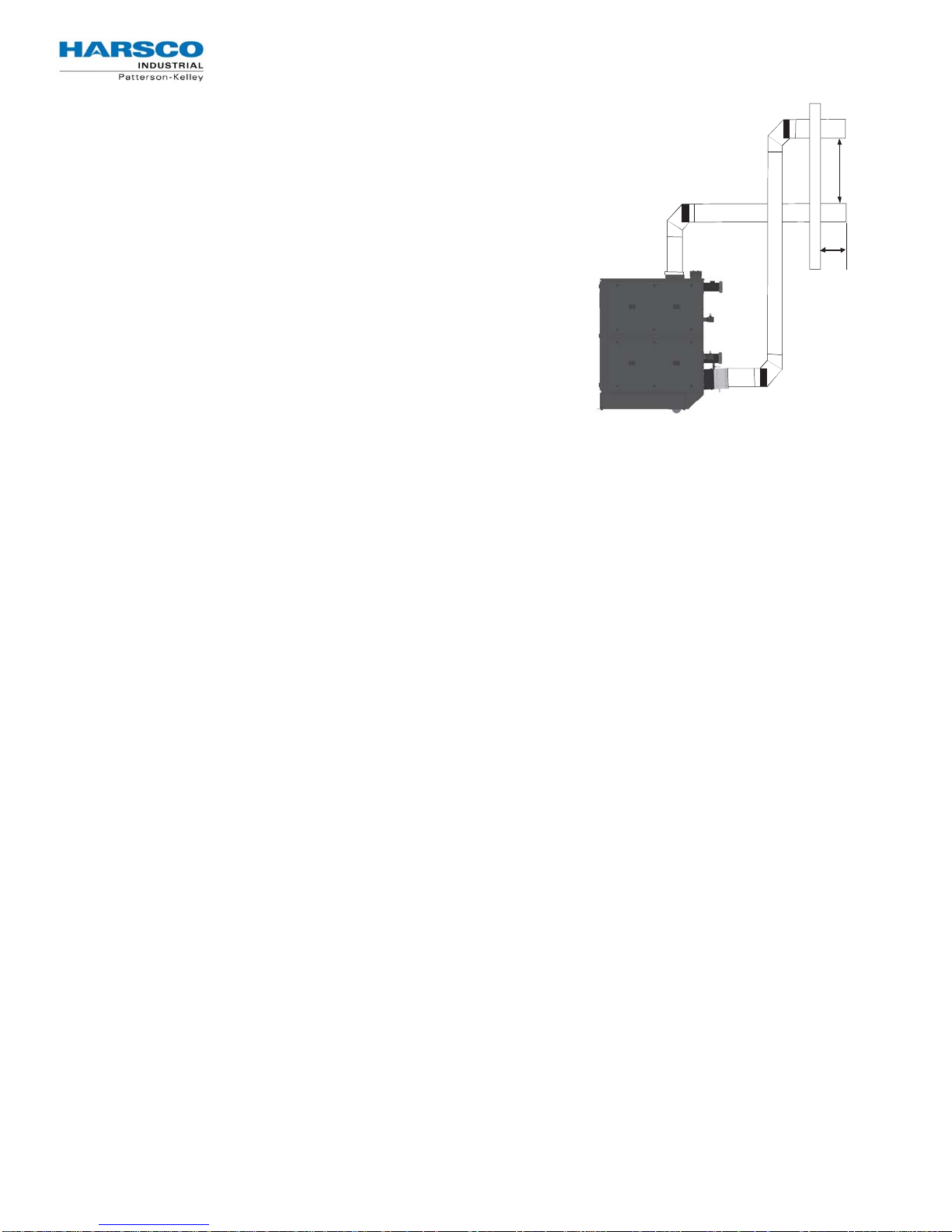
The vent shall extend at least three (3) feet above the roof, or at least two (2) feet above the highest part of any
structure within ten (10) feet of the vent. This is illustrated in the following diagram.
Additionally the boiler vent shall terminate
Figure 3.5.3.4
at least 3 ft above a forced air inlet located
within 10 ft.
To prevent the possible re-circulation of flue
gases, the vent designer must take into
consideration such things as prevailing
winds, eddy zones, building configurations,
etc. Harsco Industrial, Patterson-Kelley
cannot be responsible for the effects
such adverse conditions may have on
the operation of the boilers.
Dimensions listed above are minimums
and may not be sufficient for conditions at
a specific job site.
Vertical vents are allowed to be terminated
with a variety of ends, including plain
straight pipe, elbow or vent tee. Horizontal
vents must be terminated as illustrated in
Section 3.5.5. A bird screen with 1” x 1”
openings is recommended for the
termination. Harsco Industrial, PattersonKelley does not recommend using a vent
rain cap of any type.
Reference: NFPA 54/ANSI Z223.1 National Fuel Gas Code
3.5.4 Venting for Multiple Boilers
While the vent design parameters outlined in S ect ion 3.5.3 still apply, achieving those same parameters in a
combined vent system, adds a significant degree of complexity. Therefore, venting systems for multiple boilers
shall be designed by experienced and knowledgeable venting professionals. The venting system shall be
designed to prevent backflow of exhaust gas through idle boilers. For combined breeching installations, please
follow recommendations of a qualified venting engineer/manufacturer.
Harsco Industrial, Patterson-Kelley recommends that common venting systems be designed for a
maximum continuous exhaust pressure of -0.04” w.c. when measured in the common vent. Locking
inline dampers are recommended on the discharge of each boiler in order to maintain a slightly positive
exhaust pressure within the boiler and upstream of the damper. The -0.04” w.c. in the common flue will
help make sure the exhaust gases from an online boiler does not backflow through offline boiler(s). In
addition, Harsco Industrial, Patterson-Kelley also recommends the use of motorized dampers in the
combu s ti o n air int ake d uct to h elp prev en t the backflo w o f f l u e g as es f r om onli n e bo i lers t hr ough offline
boilers.
Harsco Industrial, Patterson-Kelley Technical Service 1.877.728.5351
25
r
Gas Fired Boile
3.5.5 Sealed Combustion/Direct Vent Systems
These boilers are also certified for operation with a sealed
Figure 3.5.5
combustion air and pressurized venting system. Such a system
employs a sealed combustion air intake duct leading from outdoors
and a sealed exhaust vent terminating outdoors. Air flow through the
36”
Minimum
system is maintained by the combustion air fan. Allowable
configurations of vent and air intake terminations are illustrated to the
right.
NOTE: Drains have been omitted for clarity.
12” Minimum
The combined pressure drop of the air supply duct and exhaust vent
must not exceed 0.44” wc. This pressure drop includes both the
inlet and exhaust duct friction loss.
NOTE: The inlet air duct loss should not exceed 0.22” w.c.
If the air inlet and the exhaust vent terminate on the same wall of the
building they must utilize the same type of termination fitting.
Allowable termination fittings are either 90° elbows or tees.
This boiler may be installed with sidewall vent using room air. (Refer to air inlet requirements Section 3.5.2.1)
Figure 3.5 .5 shows the sidewall penetration requirements. The exhaust vent must be at least 3 feet above the air
intake. The air intake and exhaust vent must extend 6" to 12" from the exterior wall and be offset.
3.5.5.1 Inlet Duct Connection to Boiler
Connect the air supply duct to the inlet air collar on the boiler. The air inlet collar is 11.875”
inlet duct to the collar with sheet metal screws at 90° angles and seal with aluminum tape or sealant.
3.5.5.2 Intake Duct Materials and Sizes
The air intake duct can be fabricated from
PVC, CPVC, single wall galvanized steel, or other suitable materials.
OD. Fasten the air
The duct must be rigid enough to maintain the full required cross sectional area under all operating conditions.
Proper sealing of the intake ductwork is necessary to prevent infiltration of air from conditioned space. Joints in
PVC or CPVC must be cemented. For galvanized duct, wrap each joint and seam with adhesive aluminum tape
or other sealant. The installation of a birdscreen on the intake termination is recommended. Ensure that the
screen does not become blocked with snow, ice, insects, etc.
3.5.6 Removing an Existing Boiler
When an existing boiler is removed from a common venting system, the common venting system is likely to be
too large for proper venting of the appliances remaining connected to it.
At the time of removal of an existing boiler, while the other appliances remaining connected to the common
venting system are not in operation, the following steps should be followed with each appliance remaining
connected to the common venting system placed in operation:
1. Seal any unused openings in the common venting system.
2. Visually inspect the venting system for proper size and horizontal pitch and determine that there is no blockage or
restriction, leakage, corrosion or other deficiency which could cause an unsafe condition.
3. Insofar as is practical, close all building doors and windows and all doors between the space in which the appliance
remaining connected to the common venting system are located and other spaces of the building. Turn on clothes
dryers and any appliances not connected to the common venting system. Turn on any exhaust fans, such as range
hoods and bathroom exhausts, so they will operate at maximum speed. Do not operate a summer exhaust fan. Close
fireplace dampers.
Harsco Industrial, Patterson-Kelley Technical Service 1.877.728.5351
26

r
4. Place the appliance being inspected in operation. Follow the lighting
instructions. Adjust the thermostat so that the appliance will operate
continuously.
5. Test for spillage at the draft hood relief opening after 5 minutes of main
burner operation. Use the flame of a match or candle or smoke from a
cigarette, cigar or pipe.
6. After it has been determined that each appliance remaining
connected to the common venting system properly vents when tested
as outlined above, return doors, windows, exhaust fans, fireplace
dampers and any other gas-burning appliance to their previous
conditions of use.
Any improper operation of the common venting system should be
corrected so the installation conforms to the National Fuel Gas
Code,
ANSI Z223.1 and CSA B149 Installation Code. When resizing
any portion of the common venting system, the common vent
system should be resized to approach the minimum size as
determined using the appropriate tables in part 11 of the National
Fuel Gas Code,
ANSI Z223.1/NFPA 54 and/or CAN/CSA B149.1
Natural Gas and Propane Installation Code.
3.6 Gas Piping
Before making the gas hook-up, make sure the boiler is being
supplied with the type of fuel shown on the boiler nameplate.
The boiler shall be installed such that the gas ignition
system components are protected from water (dripping,
spraying, rain, etc.) during appliance operation and
service (circulator replacement, control adjustment, etc.)
Figure 3.6: Simplified Gas Piping
Gas Fired Boile
All threaded connections must be
made using a pipe compound that
is resistant to the action of liquefied
petroleum gases. Do not use
Teflon tape on gas line threads!
N
OTICE
See Pipe Capacity for Natural Gas
chart on the following page for
required pipe size, based on
overall length of pipe from the
meter plus equivalent length of all
fittings. Approximate sizing may
be based on 1 cubic foot of natural
gas per 1,000 Btu per hour input,
i.e., 3,000,000 Btu/hr requires
about 3,000 cubic feet per hour.
(See “Typical Boiler Operating
Conditions,” Sec ti o n 4.4 for more
information.)
!
The boiler is factory fire-tested and adjusted for proper
combustion. The gas train components are certified to
handle a maximum inlet pressure of 14" w.c. (1/2 psig).
Typical gas pressure supply for natural gas is 7" w.c. (11"
w.c. for propane). If the available gas pressure exceeds
14" w.c., a suitable additional intermediate gas pressure
regulator of the "lock up" type must be provided to reduce
the pressure to less than 14" w.c. Refer to boiler label
for minimum inlet gas pressure.
Install a sediment trap (drip leg) and a union connection ahead of the primary manual shutoff valve on the boiler.
A gas piping schematic is shown above. Gas piping should be installed in accordance with National Fuel Gas
Code,
ANSI Z223.1, latest edition, and any other local codes which may apply; in Canada see CAN/CSA-B.149.1,
latest edition. In the Commonwealth of Massachusetts, the gas cock must be a “T-handle type.”
Table 3.6: Pipe Capacity for Natural Gas
Nominal
Iron Pipe
Size
(Inches)
2 2.067 5.17 10.3 2750 - - - - - -
2.5 2.469 6.16 12.3 4350 3000 2400 - - - -
3 3.068 7.67 15.3 7700 5300 4300 3700 - - -
Internal
Diameter
(Inches)
Equivalen t Pipe
Length
90o Ell
(Feet)
Tee
(Feet)
Maximum Capacity in Cubi c Feet of Natural Gas Per Hour Pressure
Drop of 0.5 inch Water Column/Equivalent Length of Pipe (in feet)
20 40 60 80 100 150 200
4 4.026 10.1 20.2 15800 10900 8800 7500 6700 5500 4600
Harsco Industrial, Patterson-Kelley Technical Service 1.877.728.5351
27

r
N
OTICE
The SC-2000 boiler is furnished
with 3” grooved connections and
Victaulic Style 75 couplings. The
SC-3000 and SC-4000 boilers are
furnished with 4” grooved
connections and Victaulic Style 75
couplings. These couplings must
be used with the EPDM Victaulic
seals. Isolating valves must be
installed in both the inlet and outlet
water connections.
N
OTICE
The Condensate Trap must be
piped to a drain in accordance with
all national, state and local codes.
If installed outdoors and the local
requires freeze protection, it must
be field heat traced.
!
!
Gas Fired Boile
3.6.1 Gas Supply Pipi ng by Ins taller
The boiler and all gas piping connections should be pressure-tested
and must be checked for leaks before being placed into service. Test
with compressed air or inert gas if possible.
The boiler must be disconnected at the boiler’s manual shut-off valve
(located at the end of the supplied gas train) from the gas supply piping
system during any pressure testing of the system at pressures in
excess of 1/2 psig (14" w.c.).
During any pressure testing of the gas supply piping system at
pressures equal to or less than 1/2 psig (14" w.c.), the boiler must be
isolated from the gas supply piping system by closing the manual shutoff.
Some leak test solutions, including soap and water, may cause
corrosion of the carbon steel gas pipe fittings. These leak test solutions
should be cleaned off after testing is complete.
3.7 Boiler Water Piping
3.7.1.1 Pi p ing wit h Ref r i g erat ion Lines
When installed in a two-pipe system that provides both chilled and hot
water, the control system should be configured so as to limit the time
rate of change of temperature at the boiler. Consult your authorized
Harsco Industrial, Patterson-Kelley boiler representative for application
guidance.
3.7.1.2 Piping with A ir Handling Units
The boiler piping system of a hot water heating boiler connected to heating coils located in air handling units,
where they may be exposed to refrigerated air circulation, must be equipped with flow control valves or other
automatic means to prevent gravity circulation of the boiler water during the cooling cycle.
3.7.2 Boiler Inlet and Outlet Connections
All water connections should be in compliance with national, state and local code requirements. Adapters from
Victaulic to NPT are available from Harsco Industrial, Patterson-Kelley. The bottom rear connection to the boiler is
the INLET and must be used for the return from the system. The top rear connection to the boiler is the OUTLET
and must be connected as the supply to the system. All water piping must be installed such that no stresses are
transmitted to the boiler. The boiler shall not be used as a pipe anchor.
Figure 3.7.2
Install Section IV Relief Valve Here
OUTLET ( Supply)
Possible installation location of
Section VIII Relief Valve
(SC-3000 & SC-4000 Only)
INLET (Return)
Harsco Industrial, Patterson-Kelley Technical Service 1.877.728.5351
28

r
Gas Fired Boile
3.7.3 Boiler Water Piping by Installer
Strainer
To avoid possible contamination of the boiler with dirt, rust or
sediment from the system, a strainer near the boiler inlet is strongly
recommended. Even new systems may contain sufficient foreign
material to eventually reduce the performance of the heat exchanger.
Adequate circulation of good clean water is essential for maximum
efficiency and long life of the boiler.
Relie f Valve Pipin g
Each boiler must be supplied with pressure-relief valves sized in
accordance with ASME requirements. The relief valves must be
piped to an acceptable drain. Reducing couplings or other
restrictions are not permitted in the discharge line.
The SC-2000, SC-3000 and SC-4000 boilers require an ASME
Section IV relief valve to be installed on the top of the OUTLET
(Supply) connection. The spindle of the relief valve must be vertical.
The ASME Section IV relief valves are available for purchase from
Harsco Industrial, Patterson-Kelley.
The SC-3000 and SC-4000 boilers also require an ASME Section
VIII relief valve to be installed somewhere on the boiler or connecting
piping before any isolation valve(s). A side port on the OUTLET
(Supply) connection is available for this purpose. The ASME
Section VIII relief valve is provided with the SC-3000 and SC-4000
boilers for convenience.
Low Water Cut-off
The boiler is furnished with a probe-type low water cut-off; no field
piping is required. If the water level in the boiler drops below the
probe, the boiler will shut down and
will be displayed on the control panel. The low water cutoff circuit
will automatically reset when the low water condition clears;
however the boiler controls will retain the lockout condition until the
reset button on the display is depressed. Installation of external limit
controls may be required by certain codes or in certain installations.
Review applicable local codes for details.
Drain Valve and Piping
A drain valve is factory installed in the boiler inlet (system return)
piping. Prior to draining the boiler, electrical power and gas supply
must be turned off to the boiler, and the boiler must be isolated from
the system at the supply and return connections.
Condensate Drain
The condensate is acidic (pH between 3.0 and 5.0) and may be
corrosive to some building drain systems. A condensate
neutralization system may be required and is available from Harsco
Industrial, Patterson-Kelley. If the condensate drainage system is
exposed to freezing temperatures, it must be field heat traced. The
boiler could generate up to one gallon of condensate per 100,000
BTU input. As an example, an
40 gallons per hour of condensate!
SC-4000 boiler at full fire can produce
LOCKOUT LOW WATER LEVEL
N
OTICE
The low water cutoff probe only
allows boiler operation when the
water level in the boiler is
sufficient. It does not detect low
water conditions in other parts of
the system. Installation of
additional low water safety devices
to protect the system should be
considered.
N
OTICE
This drain valve is factory installed
for draining the boiler water only,
not the entire system. Draining of
the system through the boiler will
result in depositing sediment from
the system in the boiler which will
result in poor heat transfer
characteristics of the boiler and
early boiler failure.
N
OTICE
Condensate Trap must be piped to
drain in accordance with all
national, state and local codes.
N
OTICE
Glycol or other treatment
chemicals added to the system
must be certified by the chemical
manufacturer for use in multi-metal
systems that include Stainless
Steel boilers.
N
OTICE
Under no circumstances should
petroleum based cleaning or
sealing compounds be used in the
boiler system.
N
OTICE
Under no circumstances should the
hydronic system be flushed while
the boiler is attached to the system
since the debris or corrosion
products could accumulate in the
boiler and plug the boiler’s heat
exchanger.
!
!
!
!
!
!
Harsco Industrial, Patterson-Kelley Technical Service 1.877.728.5351
29

r
3.7.4 Flushing and Filling
Water Quality
The boiler’s heat exchanger is made of stainless steel. The heat exchanger requires proper water conditions
to remain efficient and function properly. For information, please refer to Harsco Industrial Patterson Kelley
Multi- Metal Systems Water Quality Standards as it appears in Appendix 3 as this applies to the warranty of
your heat exchanger.
Never attempt to operate a boiler
that has failed to pass all the safety
checks described below.
Operating a boiler that has failed a
safety checks could result in injury.
Bypassing safety mechanisms will
result in unsafe boiler operation
which could result in injury or
death.
After checking controls by manual
adjustment, make sure they are
always reset to their proper
settings.
N
OTICE
If the expected error code(s) do not
appear, call for qualified service.
!
3.8 Pre-Start Checklist
Before attempting to start the boiler, make sure the following
items have been completed.
1. Inspect the gas train, blower, ignition electrode and boiler in general to
be sure there was no damage during shipment or installation.
2. Flue gas from the boiler is properly vented.
3. Gas connection has been made, pressure tested for leakage and the
line purged of air. Make sure all required vents have been installed.
4. Water connections are complete and the boiler and system have been
filled and purged of air.
5. The boiler is connected to the correct electrical power source listed on
the nameplate, a disconnect having adequate overload protection is
required.
6. Combustion air openings are not obstructed in any way and have
adequate capacity.
7. The boiler is placed the proper distance from any combustible walls.
8. Relief valves have been piped to an acceptable drain at a safe point of
discharge.
9. Condensate piping is properly connected.
10. Verify system water quality is within specifications.
Gas Fired Boile
3.9 Safety Checks
The following checks of safety systems must be made before putting
the boiler into normal operation.
Before firing the boiler refer to Section 4 for information on the use of
the controls, lighting, and shut-down procedures.
3.9.1 Ignition Safety System Test
Test the ignition system safety shutdown as follows:
1. Cycle the boiler on by generating a heat request. (The method for
this will depend on your boiler configuration.)
2. During the pre-purge cycle (before ignition), smoothly close the
downstream manual isolation valve (inside the boiler cabinet) to
reduce the gas flow.
3. Closing the manual isolation valve will prevent a successful
ignition, and the NURO will display either:
109: “Ignition Failed”
110: “Ignition Failure Occurred”
The user should become
thoroughly familiar with the
operation of the boiler and controls
before attempting to make any
adjustments.
Changing parameters requires an
understanding of the parameters
and the functionality of the boiler.
The boiler may not function
properly if parameters are changed
from the factory values.
These alarms indicate an ignition failure and the lockout will remain until the control is reset. After completing
this test, turn the boiler off, open the downstream manual isolation valve, then turn the boiler back on.
Harsco Industrial, Patterson-Kelley Technical Service 1.877.728.5351
30

r
Gas Fired Boile
3.9.2 Low Water Cut-out Test
The boiler is furnished with a probe-type low water cut-out. The probe is installed near the boiler’s outlet in order
to detect the presence of water at the highest possible location in the boiler and is connected to the low water cutout circuit board by a single wire. The low water cut-out circuit board is located inside the boiler’s front door, toward
the top of the control panel and is identified with a yellow label.
In order to test the low water cut-out, press and hold the red “Push to Test” button for at least 5 seconds. A manual
lockout reset error displaying 10010: “Low Water Limit” on the NURO touchscreen should occur. The red LED
indicator on the Low Water cut-off will no longer be illuminated.
Optional Test Me thod: First turn the boiler off, and then turn off the boiler’s circulating pump. Isolate the
boiler from the system. Drain the water level below the low water cut-off probe. Turn the boiler back on. It
should not operate, and a manual lockout reset error displaying 10010: “Low Water Limit”
touchscreen should occur. The red
LED indicator on the Low Water cut-off will no longer be illuminated.
on the NURO
Return the system to normal operation by refilling with water, restarting the boiler’s circulating pump, and then
turning the boiler back on.
3.9.3 Manual Reset High Temperature Limit Test
The boiler is furnished with a manual reset high temperature limit which features a probe installed near the
boiler’s outlet in order to measure the outgoing supply water temperature. This probe is connected to the manual
reset high temperature limit by a thin, metal capillary tube. The manual reset high temperature limit is located
inside the boiler’s front door, toward the top of the control panel and is identified with a yellow label.
Test the manual reset high temperature limit control as follows:
1. Cycle the boiler on by generating a heat request.
2. Allow the boiler to proceed through ignition until main flame is established.
3. Using a flathead screwdriver, turn down the setting on the manual reset high temperature limit to its
lowest value. Turning the screwdriver counter-clockwise decreases the temperature setting.
4. When the outgoing supply water temperature exceeds the setting on the manual reset high temperature
limit, the main burner will shut off.
The NURO touchscreen will display 10009: “High Temperature Limit”. Return the system to normal operation
by readjusting the setting on the manual reset high temperature limit to its default setting, press the reset button
on the manual reset high temperature limit, and finally touch any prompts from the NURO control.
3.9.4 Gas Pressure Switch Tests
Low Gas Pressure Switch
The boiler is furnished with a low gas pressure switch, installed near the boiler’s main gas shutoff/control valve.
The operation of this switch must be checked as follows:
1. Cycle the boiler on by generating a heat request.
2. Allow the boiler to proceed through ignition until main flame is established.
3. Slowly close the main gas cock while the burner is operating.
4. When the available gas pressure drops below the setting of the low gas pressure switch, the main
burner will shut off.
When the low gas pressure switch opens, the NURO touchscreen will display 10012: “Low Gas Limit”. Even
after re-opening the main gas cock, 10012: “Low Gas Limit” will remain on until the NURO display until the
boiler is manually reset.
Harsco Industrial, Patterson-Kelley Technical Service 1.877.728.5351
31

r
High Gas Pressure Switch
The boiler is furnished with a high gas pressure switch, installed near the boiler’s main gas shutoff/control valve.
The operation of this switch must be checked as follows:
1. Before starting the boiler, close the downstream gas cock located inside the boiler’s enclosure.
2. Cycle the boiler on by generating a heat request.
3. Allow the boiler to proceed to ignition.
4. When the gas pressure exceeds the setting of the high gas pressure switch, the main burner will shut
off.
When the high gas pressure switch opens, the NURO touchscreen will display 10011: “High Gas Limit”. Even
after re-opening the downstream gas cock inside the boiler, 10011: “High Gas Limit” will remain on the NURO
display until the boiler is manually reset.
Gas Fired Boile
3.10 Initial NURO Control Setup & Adjustment
This manual covers basic NURO control setup and adjustment. For a basic walkthrough of the control setup,
please refer to the NURO Getting Started Guide which is helpful for basic boiler installations. For more complex
boiler applications and more information on the parameters, please refer to the NURO Advanced User’s Guide.
Startup
When the boiler is powered on, the NURO touchscreen will display an initial Startup Screen and Rep Information
Screen (Fi gu re 3.10a & F ig ur e 3.1 0b ). After a brief time, the Rep Information Screen will timeout automatically
which will load the Home Screen (Figure 3.10c). The Home Screen shows a snapshot of the boiler’s current
operating conditions:
Outlet (Supply) Temperature
Inlet (Return) Temperature
Exhaust Temperature
Firing Rate, etc.
Figure3.10a:StartupScreen Figure3.10b:RepInformationScreen Figure3.10c:HomeScreen
Harsco Industrial, Patterson-Kelley Technical Service 1.877.728.5351
32

r
Figure3.10d:InformationScreen
Information Screen
Pressing the “Info” button in the lower left corner will load the Information Screen (Figure 3.10d). The Information
Screen contains real-time read-only boiler values such as temperatures, relay states, etc. Scroll through the
Information Screen by sliding your finger up or down.
Figure3.10e:MainMenuScreen
Figure3.10f:SetupWizard
Gas Fired Boile
This screen is helpful to determine the operating characteristics of the boiler. For more information on any value,
please refer to the NURO Getting Started Guide or the NURO Advanced User’s Guide.
Comfort Heat Setup Wizard
From the Home Screen, touch the “Settings” button in the lower right corner which will load the Main Menu
Screen (Figure 3.10e). Next, touch the “Comfort Heat Wizard” to launch the Setup Wizard (Figure 3.10f).
The first step of the Setup Wizard is to assign functionality to the user-configurable Relays A thru D. Touching
one of the Relay buttons will bring up the Relay Assignment Screen. This screen allows the user to assign
functions like “Boiler Pump”, “System Pump”, “Flame Detected” and “Air Damper” to the relays. NOTE: The
relay assignments must agree with the wiring to/from the boiler. For example, if Relay A is user-configured to
enable/disable the Boiler Pump, the control wires to operate the boiler pump must be properly wired to the Relay
A terminals in the High Voltage (TB2) terminal block. Press the “Next” button to continue.
The next step of the Setup Wizard is to define how the boiler is enabled. This will prompt the user to “Check All
That Apply”. Most installations may include a dry contact “Remote Enable” signal to the boiler. Other installations
may also use an “Outdoor Air Sensor”. Select the methods by which the boiler will be enabled or disabled for
operation. Press the “Next” button to continue.
Once the control strategy has been defined, the Setup Wizard steps through the temperature setpoints,
differentials, outdoor air reset curve (if applicable), etc. You can change these values in one of three ways:
1. Use the slider bar for quick, large temperature adjustments.
2. Use the UP or DOWN arrows for fine-tuning the temperature.
3. Touch the numeric value directly which will load a 10-digit keypad for precise control settings.
Harsco Industrial, Patterson-Kelley Technical Service 1.877.728.5351
33

r
Gas Fired Boile
Comfort Heat Operation
Once the desired temperature adjustments are complete, touch the “Home” button to return to the Home Screen.
The Home Screen will now show the temperature setpoint, and will announce the operating condition “Standby”,
“Prepurge”, “Ignition” at the top of the screen. Ensure that all external control equipment (Remote Enable,
Outdoor Air Temperature Sensor, etc.) selected during the Setup Wizard is installed and properly wired to the
boiler. The boiler is now programmed for Comfort Heat operation. For applications including Domestic Hot
Water (DHW), Cascade, etc., please refer to the NURO Getting Started Guide or NURO Advanced User’s Guide.
3.11 Fuel/Air Adjustment
The SC-2000, SC-3000 and SC-4000 boilers are equipped
with a gas/air ratio control valve and a gas safety shut off
control valve, combined into one valve assembly. The valve
functions in series with the variable speed combustion
blower to supply the correct gas/air mixture for optimum
firing performance and efficiency. The combustion blower
speed is controlled automatically by the boiler controller.
The blower speed determines the amount of air flow and the
amount of suction/negative pressure at the gas valves. The
gas valve adjusts gas flow to maintain the proper delivery
pressure at the outlet of the valve.
3.11.1 Gas Pressure Adjustment
See rating plate for the minimum and maximum gas
pressure of the boiler. The supply pressure during main
burner operation must be greater than the minimum
indicated on the rating plate. Nominal gas supply pressure
is 7” w.c. for natural gas. The gas pressure must not exceed
14” w.c. which is the maximum allowable pressure on the
gas train components. Each boiler is furnished with a
manual shut-off valve which has an integrated test port. This
port is located on the upstream side of the valve body for
measuring supply pressure. (Refer to Figure 3.11)
Figure 3.11
GasValvew/TestPort
The air flow is pre-set at the factory prior to shipment. Gas flow is dependent primarily on fan speed not upstream
gas pressure. The automatic gas valve may have to be adjusted to obtain proper combustion readings for specific
local conditions. A combustion analyzer must be used. Combustion must be set in accordance with Table 3.11.2.
3.11.2 Combustion Setup and Adjustment
To adjust/tune combustion, use the NURO’s “Manual Control Firing Rate” mode. To access, touch the “Info”
button in the lower left corner of the screen, and then touch “Service” in the lower left. Next, touch “Press to
Activate Manual Control” which will open the “Manual Control Firing Rate” mode. This test mode should be used
when adjusting or tuning the gas safety shut off/control valve on the
In this mode a heat request is required. Once the boiler cycles on and is running in “Manual Control Firing Rate”,
use the UP and DOWN arrow keys or the slider to force the boiler to operate at low fire or high fire (or anywhere
in-between). To prevent the boiler from cycling off prematurely during adjustment, ensure that any load devices
(air handlers, control valves, radiators, etc.) are in operation and able to shed/dump the heat load created by the
boiler.
Harsco Industrial, Patterson-Kelley Technical Service 1.877.728.5351
SC-2000, SC-3000 or SC-4000 boilers.
34

r
Table 3.11.2: Recommended Combustion Settings for SONIC Boilers
Fuel Nominal Gas PressureHigh Fire Setting Low Fire Sett ing
% O2 % CO2 % O2 % CO2
Natural Gas
Propane Gas
7" w.c.
11" w.c.
4.8
± 0.2
4.8
± 0.2 10.4 ± 0.3 5.0 ± 0.2 10.3 ± 0.3
9.2 ± 0.1
5.0 ± 0.2 9.1 ± 0.1
Gas Fired Boile
Adjusting High Fire
Required Tools: Flat head screwdriver and combustion analyzer
Start the boiler and observe proper operating parameters for
the system. Set boiler to the
“Manual Control Firing Rate”, as
described above, and increase the firing rate to 100%.
Check combustion readings using the combustion analyzer. If
combustion readings do not agree with Table 3.11.2, adjust as
follows:
Open the front panel of the boiler. Locate the automatic gas
valve. Turn the orifice adjusting screw, located on the
downstream side of the valve, in the direction indicated on the
sticker to increase or decrease the gas flow. Increasing the gas
flow decreases the combustion exhaust
the gas flow increases the combustion exhaust
O
, while decreasing
2
O
.
2
There will be a slight time delay between the adjustment and
the response of the
settings in small increments and allow
CO2 /O2 measuring instrument. Adjust the
the combustion readings
to stabilize before readjusting. When desired adjustments are
complete, check and adjust low fire if necessary.
Adjusting Low Fire
Required Tools: 2.5 mm hex wrench and combustion analyzer
Figure3.11.2
Start the boiler and observe proper operating parameters for
the system. Set boiler to the
“Manual Control Firing Rate”, as
described above, and decrease the firing rate to 1%. Once the
boiler has reached low fire operation, check combustion
readings using the combustion analyzer. If combustion
readings are not in accordance with Ta b l e 3 .11. 2, adjust as
follows:
Open the front panel of the boiler. Locate the automatic gas valve. Turn the offset screw, located in the bottom
center of the side of the valve, in the direction indicated on the label to increase or decrease the gas. Increasing
the gas concentration decreases the
There will be a slight time delay between the adjustment and the response of the
O
, while decreasing the gas concentration increases the O2.
2
CO2/O
measuring instrument.
2
Adjust the settings in small increments and allow the combustion readings to stabilize before readjusting. When
desired adjustments are complete, check and adjust High Fire if necessary.
3.11.3 Checking Flame Signal
Touch the “Info” button in the lower left corner of the NURO display to load the “Information” menu which
shows real-time read-only boiler values such as temperatures, relay states, etc. Scroll down the “Information”
menu to find the “Flame Signal” value. This value displays the strength of the combustion flame (units = V) as
measured by the ignition electrode/ionization probe. When the boiler is in standby, prepurge, or postpurge the
flame signal should read 0V. During main flame, a strong flame signal should read between 20-50V.
Harsco Industrial, Patterson-Kelley Technical Service 1.877.728.5351
35

6
r
Gas Fired Boile
4 Operations
4.1 General
4.1.2 NURO Control Panel
Once the boile r has been in stalled in comp liance with t his manual, it is
necessary to open the front door of the boile r in order to access the
power (on/off) switch located in the upper right hand corner of the
NURO control panel, as sho wn in Figure 4.1. 1a and Figure 4.1.1b:
Figure4.1.1a(SC‐2000) Figure4.1.2b(SC‐3000&SC‐4000)
Do not use this boiler if any part
has been under water.
Immediately call a qualified service
technician to inspect the boil er and
to replace any part of the control
system and any gas control which
has been under water. Failure to
do so could result in electrocution,
injury, or death.
If overheating occurs or the gas
supply fails to shut off, do not turn
off or disconnect the electrical
supply to the pump. Instead, shut
off the gas supply at a location
external to the boiler.
4.1.2 NURO Touch Screen Interface
Once the boiler is switched to the “ON” position, the SONIC boiler
can be programmed and operated with the NURO touch screen
interface located on the front door as shown in Figure 4.1.2. A
clear plastic cover protects the touch screen which can be opened
by pinchi ng th e clasp and swin gi n g op en to th e le ft.
4.1.3 Factory Tests
Safe lighting and other performance criteria were met with the gas
manifold and control assembly provided on this boiler when the
boiler underwent factory tests specified in
latest edition. (See "Fa c to ry
Firetest" label.)
ANSI Z21.13/CSA 4.9,
NOTICE!
The heat exc ha ng er is cons tructed
and stamp ed for 16 0 ps i g
maximum operating pressure and
210°F maximum temperature.
Figure4.1.2
Harsco Industrial, Patterson-Kelley Technical Service 1.877.728.5351
3

7
r
Gas Fired Boile
4.2 Normal Lighting and Shut-down Procedures
Normal Lighting Procedures
1. Make sure the system is filled with water and water is circulating in the system. Turn on electrical
supply and open the gas s upply valves to th e boiler.
2. Turn the on/off switch to the “On” posit ion. If an error is ind icated, refe r to the NURO Advanced User’s
Guide to troubleshoot the problem and take necessary corrective action before proceeding.
3. Set the desired high temperature limit and operating temperature. The NURO controller will now begin
the au tomatic firing sequence.
Normal Shut Down Procedures
1. Allow the boiler to turn off on its own once the
temperature satisfies, or remove the call for heat to
the bo i ler.
2. Once the boiler completes a successful “Post-
Purge” and “Post-Pump”, it will return to “St an dby”.
3. Once in standby, turn the on/off switch to the “Off”
position.
4. Close all manual gas valves (See Figure 4.3).
5. Turn off the el ectr i cal di sc o nn ec t to the boi ler .
Figure4.3
PropaneGas
4.3 Emergency Shut-Off
In cas e of emerg ency, shut off the gas supp ly at a va lve
external to the boiler. See Figure 4.3 for valve locations.
The upper shut off valve is for Propane Gas and the
lower valve for Natural Gas.
4.4 Typical Boi ler Oper ating Condition s
Table 4.4
Model
Number
SC-2000 2,000,000 208- 240 Single Less than 15
SC-3000 3,000,000
SC-4000 4,000,000
Input
(BTU/Hr)
Rating
Voltage
208-240 Three Less than 20
440-480 Three Less than 20
208-240 Three Less than 20
440-480 Three Less than 20
Phase Total
Amperage
Gas Flow Rate (CFH)
Natural
Gas
(1030 Btu/ft^3)
1942 800 1,920,000
2913 1200 2,880,000
3883 1600 3,840,000
Gas
(2500 Btu/ft^3)
LP
Output
Capacity
(Btu/hr)
NaturalGas
Harsco Industrial, Patterson-Kelley Technical Service 1.877.728.5351
3

8
r
p
Gas Fired Boile
5 Maintenance
Lockout/tagout procedure must be
employed when servicing this unit.
Failure to do so could result in
electrocution, injury, or death.
Label all wires prior to
disconnection when servicing
controls. Wiring errors can cause
improper an d da ng er ous operati o n.
Use care when reassembling main
gas line and ensure all co nn ec tions
are tight. Use a leak detector to
check for leaks before and after
servicing any compone nt of the
gas piping. Failure to do so could
result in injury or death.
Use care when servicing boiler to
prevent the ac cumulation of gas in
or around the combustion
chamber. Pockets of accumulated
gas are subj ect to combustion
and/or explosion which could result
in injury or death.
Determin e the c a us e o f any lockout
or errors before resetting the boiler.
If ab le to determine cause of
lockout, th en ap pr o pr i at e corr e c ti ve
action should be taken. If unable
to determine cause of the problem,
call a qualified service technician.
Verify prop er operation after
servicing.
Check daily to be sur e that the
boiler area is free and cle ar of any
combustible m ateria ls, including
flammable va
ors and liquids.
Harsco Industrial, Patterson-Kelley Technical Service 1.877.728.5351
5.1 Maintenance and Inspections Schedule
This schedule applies when the boiler is in use. Verify proper
operation after se rvicing. NOTE: The blower motor is permanently
lubricat ed and does no t re quir e per iodic lubr i c a ti o n.
5.1.1 Daily
Observe operating temperature and general conditions. Make
sure that the flow of combustion and ventilating air to the boiler is
not obstructed. Determine the cause of any service codes or
lockouts on the display panel. Observe any unusual noises or
operating conditions and make the necessary corrections. Notify
responsible individuals for required corrective action or repair.
5.1.2 Weekly
Observe the conditions of the main flame. A normal high fire flame
is mostly oran ge with a blue halo , while at low f ire the burner will
glow yellowish-orange.
Correct air adjustment is essential to the efficient operation of this
boiler. Ensure that the flow of combustion and ventilation air is not
obstructed.
If an adjustment in the combustion appears necessary, the flue
gas composition should be checked with a carbon dioxide (
oxygen (
3.1 1.2 of Section 3.11.2. If an adjustment to the combustion is
necessary, call a qualified and knowledgeable installer or service
agency that has been trained on the Harsco Industrial, PattersonKelley boilers.
5.1.3 Monthly
Install ation and serv i ce mu st be performe d by a qual ified and
knowledgeable installer or service agency that has been trained
on the Harsco Industrial, Patterson-Kelley boilers.
O
) analyzer and compared to the values stated in Table
2
1. Press the “Info” button on the NURO touch screen to load
the Information Screen and scroll down to view the flame signal
measured in Volts. Typical flame signals should read between
20-50V. If the flame signal is below 20V, the ignition electrode
may need to be replaced.
2. Test the low water level cut-off. Refer to Secti o n 3.9 . 2.
3. Test the manual r eset high-temp limit. Refer to Sectio n 3. 9. 3.
4. Test low gas pressure s wi tc h. Refer to Secti on 3 .9. 4.
5. Test operating temperature controls by reducing or
increasing temperature setting as necessary to check burner
operation.
6. Check the condensate drain system. Clean and flush as
necessary.
CO
) or
2
3

9
r
Gas Fired Boile
5.1.4 Semi-Annually (Required for Boilers Operated Year Round)
In addition to the recommended monthly service:
1. Clean burner of any acc um ulated dus t or li nt. Refer to Sec tion 5. 2 on "Cleaning the Burner."
2.
Inspect burner for any signs of deterioration or corrosion. Replace immediately if det eri or ation or corrosion is
evident.
3. Check the pH level of the system fluid. Verify the pH is in accordance wit h A ppendix 3.
4. Inspect and cl ean the condensate system and check for leaks. If a condensate neutrali zation kit is present, open
the lid and inspect the limestone rocks. If they are absent or have been significantl y worn away, replace them with new
limestone rocks. Use hi gh- c alcium (or pure)
limestone.
5.1.5 Annually
In addition to the recommended monthly and semi-annual service:
1. Inspect and clean the inlet screen of any accum ulated dust or lint.
2. Check burner and clean off any soot or foreign m aterial that may have accum ulated.
"Cleaning the Burner." Check for c or r osi on of the burner and its parts. If there is ev idence of deterioration or corrosion,
replace immediately. Inspect combustion chamber when the burner is removed for inspection. Note any signs of
deterioration. Clean as necessary.
3. Inspect and clean heat exchanger. Remove the vari ous cov ers to inspect the flue gas passageways. Clean t he
combustion side casting pins by flushing with clean water and blowing dry with compressed air. Do not use any
cleaning agent s or solvents. Do not use soap. A soft nylon brush may be used i n acces sibl e areas. Be sure t o i nspect
the condensate collection pan that is the lowest part of the heat ex c hanger.
4. Replace the ignition electrode and gasket .
5. Drain and flush the water side of t he heat exchanger as required ( separate f rom system fl ush) using clean water
only.
6. Inspect and clean the condensate system and check for leaks. If a condensate neutr aliz ation kit is present, open
the lid and inspect the limestone r oc k s. If they are absent or have been signif icantly worn away, replace them with new
limestone rocks. Use hi gh- c alcium (or pure) limestone.
7. Examine the venting system. Refer to the vent manufacturer's instr uctions for requir ements in addition to those
listed below.
a. Check all joints and pipe connections for tightness.
b. Check pipe for corrosi on or deterioration. If any piping needs replacing, do so immediately.
c. Inspect and clean any screens i n the vent terminal.
8. Qualified service personnel should thoroughly i nspect the heating system and correct any problem s prior to re-
starting t he boiler.
9. Qualified service personnel should thoroughly i nspect the heating system and correct any problem s prior to re-
starting t he boiler.
10. Perform combustion analysis and readjust as necessary according to Table 3.11.2 and Section 3.11.2. It is
recommended that a c opy of this report is filed for future reference.
11. P erform a leak test of the gas valves in accordance with the manufacturer' s instruc tions.
Refer to Se ction 5. 2 on
5.2 Cleaning the Burner & Combustion Chamber
Harsco Industrial, Patterson-Kelley r ec ommends cleaning the burner and combustion c ham ber at least once annually:
1. Lockout/tagout gas supply to the boiler .
2. Lockout/tagout electric al power to the boiler.
3. Disconnect the condensate neutralization tank piping in order to install a temporary drain hose into the
condensate drai n. Run the open end of this hose to a nearby floor drain.
4. Open the front and side doors of the boiler.
5. Protect the electrical and contr ol c om ponents from exposure to water with towels, a nylon t ar p, or plastic wrap.
6. Remove the wires/cables from the igniti on elec trode and flame/ionizati on r od.
7. Locate the blower and burner transition pieces located directly in the front of t he boiler. Refer to Section 6.2 for
an illustration of these components.
8. Remove the nuts and bolts connecting the blower trans ition piece to the burner transition piece. The blower
transition piece will remains supported in plac e.
9. Remove the nuts holding the burner transition piece to the studs on the front of the boil er.
10. Pull out the burner transiti on piec e with the 2 gaskets and set aside.
Harsco Industrial, Patterson-Kelley Technical Service 1.877.728.5351
3

r
11. Carefully remove the burner from the boiler and clean with pressurized water. NOTE: Do not attempt to wash the
burner while i nstalled in the boiler. When cleaning the burner, use a mild detergent such as Simple Green t o help
loosen built-up debris trapped in the burner mesh.
12. Now that t he bur ner is removed, the burner hole is open which provides access to the combustion chamber.
13. Use a pressuriz ed water hose with control noz zl e. Begin by spraying just a few seconds of water into the
combusti on chamber and then close off the nozzle.
14. Walk around to the rear of the boiler and ensure the wash water is draining into the temporar y dr ain hose off the
condensate drai n. Adjust the temporary drain hose if needed to hel p dr ain the wash water from the boiler.
15. Af ter inspecting the temporar y drain hose, continue washing the inter nal c om bustion chamber with pressurized
water for sev er al mi nutes. Spr ay as much of the internal surface area as possible. BE VERY CAREFUL when
cleaning to avoid spraying any of the electrical or cont rol c om ponents.
16. Some SONIC boiler models feature two small washout ports between the upper combusti on chamber and lower
economizer. T he plugs i n these ports can be r emoved for additional acc ess to t he fireside surfaces. If necessary,
continue washing the f ireside surfaces through these two washout por ts.
17. Af ter several minutes of washing, turn off the hose and allow all the wash water to drain f r om the boiler .
18. Rei nstall the plugs into the two washout ports (if applicable).
19. Reconnect the condensate tubing to the condensate neutralization tank.
20. Rei nstall the gasket over the boiler ’s thr eaded studs, and CAREFULLY insert the burner into the burner hole.
Support the burner so it r em ains horizontal while inserting.
21. Onc e the burner is installed, rei nstall the gasket over the burner’s flange.
22. Rei nstall the burner transition piece (and lower gasket) and bolt to t he bur ner flange.
23. Onc e secured to the burner flange, bolt t he bur ner transit ion piece to the blower transition piece. Ensure the
gasket between the burner transition piece and blower tr ansi tion piece is in place.
24.
Reinstall the i gnition electrode assembly (if previously removed).
25. Rei nstall the flame/ioniz ation rod assembly (if previously remov ed) .
26.
Reinstall t he wir es/c ables to the ignition electr ode and flame/ionization rod.
27.
Double check the tightness of all bolted joints.
Gas Fired Boile
5.3 After Repairs or Maintenance
Following any major repairs or preventative maintenance, follow the steps below before returning the boiler to
service.
1. Follow “Pre-Start Check List” (Refer to Sectio n 3.8) and all “Safety Checks” (Refer to Section 3.9).
2. Check the gas pressur e (Re f er to Section 3.11.2) and ensure proper operation of the boiler.
3. Perform combustion check (Refer to Sectio n 3.1 1. 2) and adjust air/gas mixtur e at hi gh fir e & low fir e i f
the O
NOTE: Installation and service must be performed by a qualified installer or service agency
that has been trained on the Harsco Industrial, Patterson-Kelley boiler.
% or CO2% are out of rang e.
2
Harsco Industrial, Patterson-Kelley Technical Service 1.877.728.5351
40

r
Gas Fired Boile
NOTICE!
Once the boiler begins the ignition
sequence, the firing sequence will
continu e until m ai n fl am e is
reac hed regardless of heat
request. The sequence can be
interrupted by turning the power
switch off.
If any “Manual Reset” limit device
trips, DO NOT reset without
dete r m ining and correcti ng the
cause. Manual Reset Limits
include: Flame safeguard, high or
low gas pressure, high
temperature limit, stack
temperature, low water level.
Attemptin g to op er at e a boi l er
without diagnosing the cause of
failure can result in unsafe
operation, increasing the risk of
injury. Neve r at te mpt to bypass a
safety limit device.
Figure5.4
5.4 Sequenc e of Op eration
1. When the Boiler On/Off switch i s turned on, power is provi ded thr ough
over-cur rent protection (fuse and/ or circuit br eaker) to the boil er control
and the combustion blower.
2. When the outlet water temperature drops below “CH SETPOINT”
minus “CH DIFFERE NTIAL O N”, a heat request is generated.
3. Provi ded all lim its are m ade and the r em ote enabl e signal ( if install ed)
is active, the boiler will attempt to start.
4. The NURO control c hecks to make sure air pressure switch i s open
indicati ng there is no airflow through t he boiler. The combustion blower
is then driv en towards the pre-start f an speed. When the air pr essure
switch closes, t he “PRE PURGE TIME” timer is started. Once the “PRE
PURGE TIME” timer expir es, the blower is driven to the ignition speed.
5. A trial for ignition begins and the sequence of events is illustrated
graphically below in Figure 5.4. A valid flame signal must be det ected
within 4 seconds after the gas valves open (elapsed tim e 7 seconds).
6. After a successful ignition, the fan is driven to low fire and the “CH
LOW FIRE HOLD TIME ” timer is started. Once t he “LOW FIRE HOLD
TIME” timer expires, the boiler is released to modulati on.
7. The NURO control modul ates the fi ring r ate bet ween l ow and high f i re
to maintain the desired outlet water temperature.
8. The burner will continue firing until the outlet water temperature
exceeds “CH SETPOINT” plus “CH DIFFERENTIAL OFF”. At this
temperature, the gas valves are closed com bustion air fan continues to
run until the “POST PURGE TI ME” timer has expired.
9. When the outlet water temperature is reduced by the load on the
system, a heat request is generated. The operating sequence will
recycle to
Step 3 .
Harsco Industrial, Patterson-Kelley Technical Service 1.877.728.5351
41

r
Gas Fired Boile
5.5 Troubleshooting
The NURO cont rol will d isplay graphical and/or text based erro r descriptions to announce any p roblems with
the boiler. There are two types of lockouts: manual reset lockouts which require the operator to physically
press the on-screen or device’s reset bu tton, and automatic reset lockouts which will self reset when the error
condition clears. For a comprehensive list of errors and potential resolutions, please refer to the NURO Advanced
User’s Guide.
Should the unit fail to operate, call a qualified service technician to troubleshoot the problem and implement
corrective actions.
5.5.1 Loss of Power
In the event of a power failu re, the NURO touch screen will go dark an d the entire boiler will de-energize.
The signal relays used to command auxiliary devices connected to the boiler (a ir dampers, pumps, etc.) will
also lose power, so these devices will deactivate. When power is restored, the sequence of operation will
resume a t Step 3 (Section 5.4). If any error/lock out errors were pre sent at the time of the powe r failure, the
NURO control will retain that error/lockout when power is resto red .
5.5.2 Loss of Water Level
The low water switch opens when there is an insufficient water level in the boiler. The NURO control will
display 10010: “Low Water Limit”, close the gas valve, and lock the boiler out. When the water level is
corrected and the on-screen reset button is pressed, the boiler will reset and resume the sequence of
operatio n at Step 3 (Section 5.4)
5.5. 3 Low Gas Pressure
The low gas pressure switch opens when there is (or has been) insufficient gas pressure available for proper
operation of the boiler. If an external gas-supply shut-off valve is closed for any reason, a low gas condition
will result. The NURO control will d isplay 10012: “Low Gas Limit”, close the gas valve, and lock the boiler
out. When proper gas pressure is restored, and the on-screen re set button is pressed, the boiler will reset
and resume the sequen ce o f oper ation at Step 3 (Section 5.4).
5.5.4 High Gas Pressu re
The high gas pressure switch opens when there is (or has been) excessive gas pressure for the proper
operation of the boile r. The NURO control will display 10011: “High Gas Limit”, close the gas valve, and
lock the boiler out. When proper gas pressure is restored, and the on-screen reset button is pressed, the
boiler will reset and resume the sequence of operation at Step 3 (Section 5.4).
5.5.5 Hi gh Water Temperature
When the boiler water has exceeded both the operating temperature limit and the manual reset hightemperature limit , the NURO cont rol will d isplay 10009: “High Temperature Limit”, close the gas valve, and
lock the boile r out. W hen the water te mperature falls b elow the high-limit te mperature set ting, the bo iler will
remain locked out until the water high-temperature limit switch is manually reset and the on-screen reset
button is pressed. Once reset, the control will resume the sequence of operat ion at Step 3 (Section 5.4)
5.5.6 Low Air
If the NURO control displays either 65: “Interrupted Airflow Switch OFF” or 66: “Interrupted Airflow
Switch ON”
when the boiler is in “Standby”, the blower should also be in standby.
, this indicates improper airflow through the boiler. First, verify proper standby blower operation –
Next, check for obstructions of the combustion air intake and/or exhaust (flue) piping. Next, check the hoses
leading to the air switches are not kinked or obstructed. An error related to the air switch does not
necessarily mean that the air switch is defective.
When 6 6: “ Inte rru pte d Airf lo w Sw itch ON” is displayed, check that the air switch is open when the blower
is offline. Ensure there is no air flow through the boiler when the blower is offline. An excessive negative
draft in the flue piping can cause air flow through the offline boiler which may be strong enough to maintain
closure of the air switch.
Harsco Industrial, Patterson-Kelley Technical Service 1.877.728.5351
42

3
r
When 65: “Interrupted Airflow Switch OFF” is displayed, check that the air switch is closed when the
blower is running. If the air switch does not close within 5 minutes during purge, the boiler locks out. Check
that the burner is clean ("Cleaning the Burner," S ecti o n 5. 2) and that there are no obstructions to airflow in the
intake or exhaust ducts.
5.5.7 Flame Failure
In the event of a flame failure, the NURO control may display one of the following error messages:
106: “Flame Lost in Main Flame Establish Period”
107: “Flame Lost Early in Run”
108: “Flame Lost in Run”
109: “Ignition Failed”
110: “Ignition Failure Occurred”
When 10 9: “Ignition Failed” or 110: “Ignition Failure Occurred” is displayed, the boiler did not light during
the trial for ignition. Check that the ignition electrode, ignition wire, and gas valve are functioning properly.
Check that the direct spark ignition is visible through the flame observation port during the trial for ignition.
When 106: “Flame Lost in Main Flame Establish Period”, 107: “Flame Lost Early in Run”, or 108: “Flame
Lost in Run”
properly, the gas pressure is correct, and the ignition electrode, ignition wire, and gas valve are functioning
properly.
5.5.8 Flame Error
is displayed, the boiler lost the flame signal during operation. Check that combustion is adjusted
Gas Fired Boile
In the event of a flame error (premature or late flame signal), the NURO control will display 105: “Flame
Detected Out of Sequence”. This may be caused by a failed/leaky gas valve or a flame rod or ionization
rod malfunction. If gas valve leakage is suspected, the unit must be isolated by turning off the main gas
supply line. Lockout/tagout the boiler until qualified and knowledgeable service personnel are available to
evaluate and repair or replace the failed parts. Check that the incoming gas pressures have not exceeded
14” w.c. (1/2 psig).
5.5.9 Flue Problem
When the no rmally-closed high e xhaust bac k pressure switch opens , the NURO cont rol will display 10013:
“High Back Pressure Limit”. This may be caused by an obstruction in the flue piping, an obstruction in the
combustion air intake, or a blocked condensate system. When the blockage is removed, the boiler will
automatically restart. If no blockage is found, it may be necessary to replace the high exhaust back pressure
switch.
Harsco Industrial, Patterson-Kelley Technical Service 1.877.728.5351
4

r
Gas Fired Boile
6 Parts/Tech Support
Use of Non-Factory Authorized
replacement parts are not
recommended for this equipment.
All control components are
engineered for safety and are
designed to work in unison with
each of the other components.
Use of non-factory authorized
replacement parts jeopardizes the
functionality of the safety features
as well as the performance of the
boiler.
Spare parts and replacement parts can be ordered from Harsco
Industrial, Patterson-Kelley by calling toll free (877) 728-5351.
Reach us by fax at (570) 476-7247.
Refer to the parts list shown on the assembly drawings provided in
this manual.
Technical information is also available by calling or visit the Harsco
Industrial, Patterson-Kelly website, www.harscopk.com.
When ordering replacement parts please have the model number
and serial number of your boiler available.
Typical schematic drawings are shown on the following pages.
Drawings specific to your particular boiler can also be supplied by
your local Harsco Industrial, Patterson-Kelley representative.
6.1 Wiring Diagrams
6.1.1 Terminal Block Assignments – Power Box (SC-3000 & SC-4000 Only)
The power box is located in the front of the boiler, at the lower left corner. This power box houses the control
transformer, fuses, the power box terminal strip circuit breakers, and the blower motor relay.
The three phase circuit breaker is mounted on
The terminals on the circuit breaker can accommodate maximum 10AWG wire. There is an additional terminal
on the
DIN rail for a ground connection. Refer to the Ratings Nameplate on the back surface of the boiler to verify
the required electrical supply prior to connection.
DIN rail and allows for direct connection of the three power leads.
Figure 6. 1.1 Power Box Wiring Diagram (240V Configuration Shown)
Harsco Industrial, Patterson-Kelley Technical Service 1.877.728.5351
44

r
6.1.2 Term i n al Bl o ck Assi gn ments — High Vol t ag e (TB2) Terminal Block
Gas Fired Boile
SC-2000
Terminal
Number
25 22
24 21
23 20
22 19
21 18
20 17
19 16
18 15
17 14
16 13
N/A 12
15 11
14 10
13 9
12 8
11 7
10 6
9 5
8 4
7 3
6 2
5 1
4 N/A
3 N/A
2 N/A
1 N/A
SC-3000
SC-4000
Terminal
Number
Label Description
MASTER ALARM RELAY
MASTER ALARM RELAY
RELAY A
RELAY A
RELAY B
RELAY B
RELAY C
RELAY C
RELAY D
RELAY D
GROUND
GROUND
[120V+] AIR DAMPER
AIR DAMPER INTERLOCK
[120V+] AUXILIARY #1
AUXILIARY INPUT #1
[120V+] AUXILIARY #2
AUXILIARY INPUT #2
START INTERLOCK #1
START INTERLOCK #1
START INTERLOCK #2
START INTERLOCK #2
GROUND G1 for 208-240VAC, Single phase, 60Hz
NEUTRAL N1 for 208-240VAC, Single phase, 60Hz
HOT L2 L2 for 208-240VAC, Single phase, 60Hz
HOT L1 L1 for 208-240VAC, Single phase, 60Hz
Normally-Open Dry Contact, Close on Alarm
(240VAC Max Voltage & 1/2Amp Max Current)
User-Configurable Normally-Open Dry Contact A
(240VAC Max Voltage & 1/2Amp Max Current)
User-Configurable Normally-Open Dry Contact B
(240VAC Max Voltage & 1/2Amp Max Current)
User-Configurable Normally-Open Dry Contact C
(240VAC Max Voltage & 1/2Amp Max Current)
User-Configurable Normally-Open Dry Contact D
(240VAC Max Voltage & 1/2Amp Max Current)
Ground Terminals for I/O Devices
120VAC Pilot-Duty for Air Damper End Limit Switch
Contact Closure When Air Damper Proven Open
Reserved for Future Use
Reserved for Future Use
External Interlock Circuit #1
External Interlock Circuit #2 (In Series w/ #1)
Harsco Industrial, Patterson-Kelley Technical Service 1.877.728.5351
45

r
6.1.3 Term i n al Bl o ck Assi gn ments — Low Voltage (TB1) T erminal Bl o ck
Terminal Number Label Description
Gas Fired Boile
27
26
25
24
23
22
21
20
19
18
17
16
15
14
13
12
11
10
9
8
7
6
5
4
3
2
1
ECOM 3
ECOM 2
ECOM 1
MODBUS SHIELD
MODBUS COM B
MODBUS COM A
MODBUS/CASCADE REF
CASCADE B TO B
CASCADE A TO A
CASCADE SHIELD
GROUND
ANALOG OUTPUT [-]
4-20mA ANALOG OUTPUT [+]
NIGHT SETBACK
NIGHT SETBACK
OUTDOOR TEMP SENSOR
OUTDOOR TEMP SENSOR
DHW STAT / SENSOR
DHW STAT / SENSOR
HDR TEMP SENSOR
HDR TEMP SENSOR
SPARE ANALOG INPUT
SPARE ANALOG INPUT
ANALOG INPUT [-]
4-20mA ANALOG INPUT [+]
ENABLE / DISABLE
ENABLE / DISABLE
Wireless Outdoor Air Receiver
2-Wire MODBUS RS485 & Shield Terminal
Reference Terminal (Application Dependent)
2-Wire Cascade & Shield Terminal
Ground Terminal for I/O Devices
4-20mA Analog Output Tracks Boiler Firing Rate
100% Firing Rate = 20mA, 1% Firing Rate = 4mA
Contact Closure Enables Night Setback Operation
Open Circuit Disables Night Setback Operation
Outdoor Air Temperature Sensor for ODA Reset
Configurable for 10kΩ or 12kΩ Sensor
DHW Enable Circuit Configurable for SPST Break-onrise Aquastat, or 10kΩ or 12kΩ Tank Sensor
Hydronic Supply Header Temperature Sensor
Configurable for 10kΩ or 12kΩ Sensor
Reserved for Future Use
4-20mA Analog Input
Configurable for Setpoint or Firing Rate Control
Contact Closure Enables Comfort Heat Operation
Open Circuit Disables Comfort Heat Operation
Harsco Industrial, Patterson-Kelley Technical Service 1.877.728.5351
46

r
6.1.4 SC-3000 & SC-4000 Control Transformer Diagrams
Gas Fired Boile
Figure 6. 1.4 a SC-3000 & SC-4000: 208 VAC, three phase, 60 hertz:
Before making any electrical
connections to the boiler, verify
that the control transformer is
properly configured for the
applicable incoming power supply
to the boiler:
208V, three phase, 60Hz
220-240V, three phase, 60Hz
440-480V, three phase, 60Hz
Improper configuration of the
control transformer could result in
serious injury or death.
Figure 6. 1.4b SC-300 0 & SC- 40 00 : 22 0- 2 40 VAC, three phas e, 60 hertz:
Harsco Industrial, Patterson-Kelley Technical Service 1.877.728.5351
47

r
Figure 6. 1.4 c SC-3000 & SC-4000: 440-480 VAC, three phase, 60 hertz:
Gas Fired Boile
Harsco Industrial, Patterson-Kelley Technical Service 1.877.728.5351
48

r
6.1.4 SC-2000 Wiring Diagram
Gas Fired Boile
Harsco Industrial, Patterson-Kelley Technical Service 1.877.728.5351
49

r
Gas Fired Boile
Harsco Industrial, Patterson-Kelley Technical Service 1.877.728.5351
50

r
6.1.5 SC-3000 & SC-4000 240V Wiring Diagram
Gas Fired Boile
Harsco Industrial, Patterson-Kelley Technical Service 1.877.728.5351
51

r
Gas Fired Boile
Harsco Industrial, Patterson-Kelley Technical Service 1.877.728.5351
52

r
6.1.6 SC-3000 & SC-4000 480V Wiring Diagram
Gas Fired Boile
Harsco Industrial, Patterson-Kelley Technical Service 1.877.728.5351
53

r
Gas Fired Boile
Harsco Industrial, Patterson-Kelley Technical Service 1.877.728.5351
54

r
Gas Fired Boile
6.2 Boiler Parts Identification (SC-2000)
6.2.1 Main Boiler Assembly (SC-2000)
7
1
2
3
4
6
5
Mark Description
1 HeatExchanger 5 FrontDoor/NUROTouchscreen
2 Burner/BlowerAssembly 6 NUROControlPanel
3 CabinetBase 7 SheetMetalCabinet
4 NaturalGasTrain
Mark Description
Harsco Industrial, Patterson-Kelley Technical Service 1.877.728.5351
55

r
r
r
6.2.2 NURO Control Panel (SC-2000)
1
2
Gas Fired Boile
3
4
7
5
6
12
8
11
10
9
Mark Description
1 PushtoTestLWCOButton 7 NUROTouchscreenAssembly
2 ManualResetHiTempLimit 8 ClearPlasticProtectiveCove
3 CircuitBreake
4 On/OffSwitch 10 LowVoltage(TB1)TerminalBlock
5 SOLAMainboard 11 TransformerXFMR2(40VA)
6 IgnitionCable 12 TransformerXFMR1(20VA)
Mark Description
9 HighVoltage(TB2)TerminalBlock
Harsco Industrial, Patterson-Kelley Technical Service 1.877.728.5351
56

r
6.2.3 Heat Exchanger Assembly (SC-2000)
Gas Fired Boile
1
14
13
15
2
3
4
5
6
7
12
11
10
8
9
Mark Description
1 OutletCoupling(3”Victaulic) 9 HighExhaustPressureSwitchPort
2 ReliefValvePort 10 HeatExchanger
3 SupplyTemperatureSensor 11 HeatExch.TemperatureSensor
4 InletCoupling(3”Victaulic) 12 BurnerFlange/Hole
5 ManualDrainValve 13 LowWaterCutoffProbe
6 10”FlueAdapter 14 ManualResetHighLimitProbe
7 CondensatePan 15 AutomaticAirVent
8 CondensateTrap
Harsco Industrial, Patterson-Kelley Technical Service 1.877.728.5351
Mark Description
57

r
6.2.4 Natural Gas Train, Burner & Blower Assembly (SC-2000)
12
11
10
9
Gas Fired Boile
1
15
2
14
8
7
5
6
13
3
4
Mark Description Mark Description
1 StainlessSteelMeshBurner 9 BlowerTransitionPiece
2 External(Upstream)GasCock 10 CombustionBlower/Fan
3 GasPiping&Supports 11 BurnerTransitionPiece
4 AirIntakeTransitionPiece 12 IgnitionElectrode&Gasket
5 LowGasPressureSwitch 13 Flame/IonizationRod&Gasket
6 HighGasPressureSwitch 14 OuterBurnerGasket
7 MainGasShutoff/ControlValve 15 InnerBurnerGasket
8 Internal(Downstream)GasCock
Harsco Industrial, Patterson-Kelley Technical Service 1.877.728.5351
58

r
Gas Fired Boile
6.3 Boiler Parts Identification (SC-3000 & SC-4000)
6.3.1 Main Boiler Assembly (SC-3000 & SC-4000)
8
1
2
3
4
7
5
6
Mark Description
1 HeatExchanger 5 MainPowerBox
2 Burner/BlowerAssembly 6 FrontDoor/NUROTouchscreen
3 CabinetBase 7 NUROControlPanel
4 NaturalGasTrain 8 SheetMetalCabinet
Mark Description
Harsco Industrial, Patterson-Kelley Technical Service 1.877.728.5351
59

r
r
T
T
6.3. 2 NURO Contr ol Panel (SC-3 000 & SC-4000)
1
Gas Fired Boile
12
2
3
4
5
6
7
11
8
10
9
Mark Description Mark Description
1 PushtoTestLWCOButton 7 NUROTouchscreenAssembly
2 ManualResetHiTempLimit 8 ClearPlasticProtectiveCove
3 FuseHolder&Fuse 9 HighVoltage(TB2)TerminalBlock
4 On/OffSwitch 10 LowVoltage(TB1)TerminalBlock
5 SOLAMainboard 11
6 IgnitionCable 12
ransformerXFMR2(40VA)
ransformerXFMR1(20VA)
Harsco Industrial, Patterson-Kelley Technical Service 1.877.728.5351
60

r
r
6.3.3 Main Power Box (S C-3000 & SC-4000)
1
2
3
4
Gas Fired Boile
5
Mark Description Mark Description
1 20AThreePhaseBreaker
(IncomingThreePhasePower)
2 GroundingTerminal 5 PowerLeadtoBlowerMotor
3 ControlTransformer 6 BlowerMotorRelay
6
4 FuseHolde
Harsco Industrial, Patterson-Kelley Technical Service 1.877.728.5351
61

r
6.3.4 Heat Exchanger Assembly (SC-3000 & SC-4000)
18
17
16
15
Gas Fired Boile
1
2
3
4
14
13
12
11
10
Mark Description
1 OutletCoupling(4”Victaulic) 10 HighExhaustPressureSwitchPort
2 ASMESectionVIIIReliefValve(150#) 11 SectionVIIIEconomizer
3 SupplyTemperatureSensor 12 InterconnectingElbows
4 Nuts/Bolts 13 InternalCouplings(2‐1/2”Victaulic)
5 InletCoupling(4”Victaulic) 14 BurnerFlange/Hole
6 ManualDrainValve 15 LowWaterCutoffProbe
7 10”FlueAdapter 16 SectionIVBoiler
8 CondensatePan 17 ManualResetHighLimitProbe
9 CondensateTrap 18 AutomaticAirVent
Mark Description
9
5
6
7
8
Harsco Industrial, Patterson-Kelley Technical Service 1.877.728.5351
62

r
6.3.5 Natural Gas Train, Burner & Blower Assembly (SC-3000 & SC-4000)
Gas Fired Boile
12
11
10
9
8
1
14
2
13
4
7
3
5
6
Mark Description Mark Description
1 StainlessSteelMeshBurner 8 HighGasPressureSwitch
2 External(Upstream)GasCock 9 BlowerTransitionPiece
3 GasPiping&Supports 10 BurnerTransition Piece
4 BlowerMotorSplashGuard 11 Flame/IonizationRod&Gasket
5 CombustionBlower/Fan 12 IgnitionElectrode&Gasket
6 LowGasPressureSwitch 13 OuterBurnerGasket
7 MainGasShutoff/ControlValve 14 InnerBurnerGasket
Harsco Industrial, Patterson-Kelley Technical Service 1.877.728.5351
63

r
6.3.6 Propane Gas Train (SC-30 00 & SC- 4 00 0)
Gas Fired Boile
1
7
6
2
4
3
5
Mark Description
1 External(Upstream)GasCock 5 Internal(Downstream)GasCock
2 GasPiping&Supports 6 HighGasPressureSwitch
3 FlexibleGasHose 7 MainGasShutoff/ControlValve
4 LowGasPressureSwitch
Harsco Industrial, Patterson-Kelley Technical Service 1.877.728.5351
Mark Description
64

r
Gas Fired Boile
7 Limited Warranty
Harsco Industrial, Patterson-Kelley Technical Service 1.877.728.5351
65

r
Gas Fired Boile
Boiler Fire-Test Report
Harsco Industrial, Patterson-Kelley Technical Service 1.877.728.5351
66

r
Gas Fired Boile
Appendix 1: Maintenance Log
Date
Hi Fire /
Low Fire
O2 CO CO2
Stack
Temp
pH Action By
Harsco Industrial, Patterson-Kelley Technical Service 1.877.728.5351
67

r
Gas Fired Boile
Appendix 2: Boiler Altitude Derate Schedule
For installations over 2000 ft. elevations, a derate schedule is applied. The boiler input rating must be reduced
by 4% per 1000 ft. which is illustrated in the graph below.
Derate procedure is as follows:
With the boiler at high fire, adjust the gas valves (as described in Section 3.10.4) to get 5% O2 in the flue gas. If
this cannot be achieved, perform the following steps:
•
If the O2% is too high, then the inlet gas pressure should be adjusted to the minimum pressure allowed,
typically 5” wc The gas valve should be adjusted to obtain approximately 5% O2. If the O2% is still too high,
the fan speed may be lowered. This procedure should only be performed by factory trained personnel.
•
If the O2% is too low, then the gas valve settings should be reduced. This procedure is also described in
Bulletin 06-08.
Harsco Industrial, Patterson-Kelley Technical Service 1.877.728.5351
68
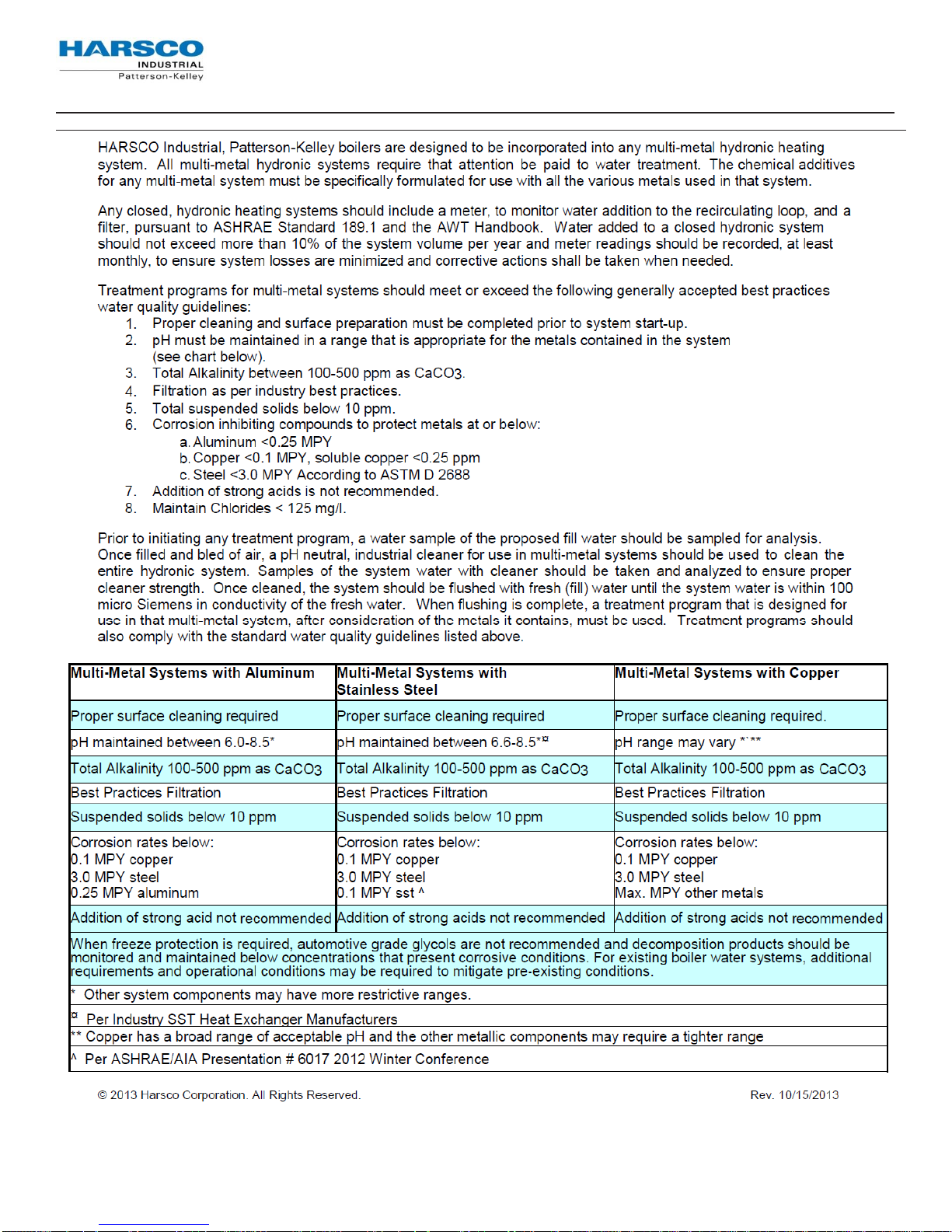
r
Gas Fired Boile
Appendix 3: Water Quality Standards for Hydronic Boilers in Multi-Metal Systems
Harsco Industrial, Patterson-Kelley Technical Service 1.877.728.5351
69
 Loading...