

Harsco Industrial SC-1500, SC-2000, SC-3000, SC-4000 Owner's Manual
INSTALLATION
&
O W N E R’S
P-K SONIC® / NURO® GAS FIRED BOILER
INSTALLATION
&
SC-1500/SC-2000
SC-3000/SC-4000
Natural Gas/Propane/Dual Fuel
Part # 1004905978
C.S.A Design-Certified
Complies with ANSI Z21.13/CSA 4.9
Gas-Fired Low Pressure Steam and Hot Water Boilers
ASME Code, Section IV
Certified by Patterson-Kelley
C.S.A Design-Certified
Complies with ANSI Z21.13/CSA 4.9
Gas-Fired Low Pressure Steam and Hot Water Boilers
Model Number:
Serial Number:
Start-Up Date:
Harsco Industrial, Patterson-Kelley
155 Burson Street
East Stroudsburg, PA 18301
Telephone: 570.476.7261
Toll Free: 877.728.5351
Fax: 570.476.7247 www.harscopk.com
HARSCO Industrial, Patterson-Kelley 2015: All Rights Reserved.
The information in this manual is the property of Harsco Industrial Patterson-Kelley. The descriptions and specifications contained in this manual were in
effect at the time this manual was approved for publication. While Harsco Industrial Patterson-Kelley will continue to support earlier model boilers to
within a reasonable time limit, we reserve the right to discontinue models and replacement parts at any time or change specifications or design without
notice and without incurring any obligation.
Revised August 1, 2015
INSTALLATION
&
INSTALLATION
&
INSTALLATION
&
INSTALLATION
&
INSTALLATION
&
INSTALLATION
&
MANUA
O W N E R’S
MANUA
O W N E R’S
MANUA
O W N E R’S
MANUA
O W N E R’S
MANUA
O W N E R’S
MANUA
O W N E R’S
MANUA
O W N E R’S
MANUA
L
L
L
L
L
L
L
L
P-K
SONIC
TM
Gas Fired Boiler
Safety
TTTTechnical Service 1.877.728.5351
echnical Service 1.877.728.5351
echnical Service 1.877.728.5351echnical Service 1.877.728.5351
General
P-K SONIC TM SC-1500, SC-2000, SC-3000 and SC-4000
All P-K SONIC TM SC-1500, SC-2000, SC-3000 and SC-4000
Gas-Fired Boilers must be:
• Installed, operated, and serviced in accordance with
• Installed by qualified personnel in accordance with designs
• Operated and serviced in accordance with a comprehensive
• Operated and serviced by experienced, qualified, and
Safety Precautions
Provide a suitable location for the boiler, away from normal
personnel traffic, with adequate working space, adequate
clearances, proper ventilation and lighting, with a structure
sufficiently strong and rigid to support the weight of the boiler, all
piping, and accessories.
instructions contained in this manual and other supplemental
manuals.
prepared by qualified facility engineers including: structural,
mechanical, electrical, and other applicable disciplines.
safety program determined and established by the customer.
Do not attempt to operate or service until such a program
has been established.
properly trained personnel in accordance with all applicable
codes, laws, and regulations.
N
OTICE
Each safety device must be
maintained and checked per the
recommended schedule. Refer to
Section 5 Maintenance.
S
AFETY FEATURES
It is the responsibility of the
customer to ensure external
safety provisions, such as but not
limited to: guards, safety labels,
safety controls, interlocks, lockout
devices are in place and operable.
S
AFETY LABELS
The following words are used in
this manual to denote the degree
of seriousness of the individual
hazards.
hazardous situation which,
if not avoided, will result in
death or serious injury. This
signal word is to be limited
!
Indicates an imminently
to the most extreme
situations.
Indicates a potentially
hazardous situation which, if
not avoided, could result in
death or serious injury.
N
Is the preferred signal word to
address practices not related to
personal injury. The safety alert
symbol is not used with this signal
word.
Indicates a potentially
hazardous situation which, if
not avoided, may result in
minor or moderate injury. It may
also be used to alert against
unsafe practices.
OTICE/NOTE - NOTICE
P-K
SONIC
TM
Gas Fired Boiler
N
OTICE
!
Training
TTTTechnical Service 1.877.728.5351
echnical Service 1.877.728.5351
echnical Service 1.877.728.5351echnical Service 1.877.728.5351
The safety labels shown below are
affixed to your boiler. Although the
labels are of high quality, they may
become dislodged or unreadable
over time. Contact Harsco Industrial,
Patterson-Kelley at 570.476.7261 or
toll-free at 877.728.5351 for
replacements.
Proper training is the best protection against accidents. It is
essential to read, understand, and follow the recommendations
of this manual before installing, operating, or servicing this
equipment. Failure to do so could result in fire or explosion and
serious injury, death, and/or property damage.
Operating and service personnel must be thoroughly familiar with
the basic construction of the SC-1500, SC-2000, SC-3000 and
SC-4000 boilers, the use and locations of the controls, the
operation of the boilers, adjustment of their various mechanisms,
and all applicable safety precautions. If any of the provisions of
this manual are not fully and completely understood, contact
Harsco Industrial, Patterson-Kelley Technical
570.476.7261 or toll free at 877.728.5351.
Electrical Hazards
Crush Hazards
Boiler Model Boiler Size Weight in Pounds
Gas may lose its odor. Proper gas
sensing equipment and procedures
should be used for leak checks.
Failure to detect gas leaks could
result in injury or death.
Bump Hazard from Overhead Ductwork and Piping
Injury Hazard! Install components with adequate vertical clearance.
Pressure Hazards
SC-1500 1,500,000 BTU 1,450 lbs
SC-2000 2,000,000 BTU 1,450 lbs
SC-3000 3,000,000 BTU 1,850 lbs
SC-4000 4,000,000 BTU 1,900 lbs
Service at
Hazard Warnings
Shock Hazard! Properly lockout/tagout the electrical
service and all other energy sources before working
on or near the boiler.
Shock Hazard! Do not spray water directly on this
boiler or any electrical components.
Electrical Hazard! Do not alter wiring connections.
Lifting Hazards! Use properly rated lifting
equipment to lift and position the boiler. The load is
unbalanced. Test the balance before lifting off the
floor. Do not allow personnel beneath the lifted
load. Refer to the approximate weights in the table.
Pressure Hazard! Hot fluids. Install isolation valves on boiler water inlet and outlet.
Make sure isolation valves are closed before servicing boiler.
Pressure Hazard! Hot fluids. Annually test safety relief valve(s) for proper operation.
Do not operate boiler with faulty relief valve(s).
P-K
SONIC
TM
Gas Fired Boiler
TTTTechnical Service 1.877.728.5351
echnical Service 1.877.728.5351
echnical Service 1.877.728.5351echnical Service 1.877.728.5351
Slip, Fall Hazards
Tripping Hazard! Do not install piping on floor surfaces. Maintain a clear path around the boiler.
Slip and Fall Hazard! Use a drip pan to catch water while draining the boiler. Maintain dry floor
surfaces.
Slip and Fall Hazard! Do not locate intake or exhaust terminations above a walkway; dripping of
condensate can cause icing of the walking surface. Refer to Section 2.4.6.
Fall Hazard! Do not stand on boiler.
Chemical Hazards
Chemical Hazards from Cleaning Products. Use
caution when cleaning the system. The use of professional
assistance is recommended. Use safe procedures for the
disposal of all cleaning solutions.
Combustion Condensate – An acidic pH of
approximately 3.0 to 5.0 can be expected. Use PVC, CPVC, or other corrosion resistant piping for
drainage. Collection and disposal must be in accordance with all applicable regulations. A condensate
neutralization kit is available. Please contact your local Harsco Industrial, Patterson-Kelley representative for
more information.
Burn, Fire and Explosion Hazards
Burn, fire, and explosion hazards! Installation must be in strict conformance to all applicable
and standards including NFPA 54, ANSI Z223.1 and CAN/CSA B.149. Install all required vent
codes
lines for gas devices. Refer to Section 3.3 and Section 3.4.
Hazard from Incorrect Fuels! Possible fire, explosion, overheating, and damage. Do not use any
fuels except the design fuels for the unit.
Overfire Hazards! High pressure in gas supply could result in overfiring of this or other devices
supplied from the same source.
Fire and Explosion Hazards! Close the main gas shutoff before servicing boiler.
Fire and Explosion Hazards! Do not store or use gasoline or other flammable vapors or liquids in
the vicinity of this or any other gas fired appliance.
Burn hazard! Possible hot surfaces. Do not touch gas vent during firing operation. Use only factory
recommended vent components.
Burn Hazard! Pipes, vents, and boiler components could be hot. Do not touch piping or stack surfaces during
operation or immediately after shutdown of the boiler.
Burn Hazard! Hot flue! Use caution when servicing or draining boiler.
Fire and Explosion Hazards! Use caution when servicing burner. Propane (LPG) is heavier than air and may linger
in the combustion chamber, vent lines, or elsewhere.
Gas Leak Hazard! Make sure the burner is installed correctly and blower/transition is securely fastened following
any maintenance performed on them. These connections may leak gas if assembled incorrectly.
Gas Leak Hazard! All threaded gas connections must be made using a pipe compound that is resistant to liquefied
petroleum gas. Do not use Teflon™ tape on threaded gas piping.
Gas Leak Hazard! Check entire gas train for leaks after installation. If there is a smell of gas, shut down the boiler
and obtain immediate assistance from trained service personnel and/or your local fire department.
Overfire Hazard! Possible fire and explosion from excess gas pressure. Make sure that gas inlet pressure does not
exceed 14 inches W.C.
Overfire Hazard! Possible fire and explosion. Possible malfunction of regulators and/or gas safety shut off/control
valves. Maintain all gas train components in good condition. Do not alter wiring connections. Annual inspection by
factory-trained personnel for proper set-up and operation is recommended.
Overfire and Underfire Hazards! Possible fire, explosion, overheating, and component failure. Do not attempt to
adjust firing rate of the boiler. The firing rate must be adjusted only by factory trained personnel.

P-K
SONIC
TM
Gas Fired Boiler
TTTTechnical Service 1.877.728.5351
echnical Service 1.877.728.5351
echnical Service 1.877.728.5351echnical Service 1.877.728.5351
Table of Contents
D
OCUMENT REVIEW AND ACCEPTANCE
R
EVISION HISTORY
................................................................ E
1 INTRODUCTION ..................................................... ERROR! BOOKMARK NOT DEFINED.
................................... E
RROR! BOOKMARK NOT DEFINED
RROR! BOOKMARK NOT DEFINED
.
.
1.1 P
1.2 U
1.3 HARSCO I
URPOSE OF THIS DOCUMENT
SING THIS MANUAL
NDUSTRIAL, PATTERSON-KELLEY PRODUCT ABBREVIATIONS
..................................................................................................... 5
....................................................................................... 5
.......................... 5
2 SITE PREPARATION......................................................................................................... 6
2.1 R
ECEIVING AND STORAGE
............................................................................................. 6
2.1.1 Initial Inspection ...................................................................................................... 6
2.1.2 Storage Prior to Installation ..................................................................................... 6
2.2 C
2.3 L
OMPLIANCE WITH CODES
OCATION SETUP
......................................................................................................... 7
............................................................................................ 6
2.3.1 Placement ............................................................................................................... 7
2.3.2 Clearances .............................................................................................................. 7
2.4
I
NLET AIR AND EXHAUST VENTING CONSIDERATIONS
....................................................... 8
2.4.1 Applicable Codes and Standards ............................................................................ 8
2.4.2 Gas Vent Category Planning ................................................................................... 9
2.4.3 Air Inlet Planning (United States and Canada Considerations) ................................ 9
2.4.4 Flue Venting Considerations ................................................................................... 9
2.4.5 Venting Materials for Flue/Exhaust Systems............................................................ 9
2.4.6 Required Clearances ............................................................................................ 10
2.4.6.1 Conventional Vent Systems Clearances ........................................................ 10
2.4.6.2 Direct Vent (Sealed Combustion) Systems Clearances ................................. 10
2.4.6.3 Interior Component Clearances ..................................................................... 11
2.4.6.4 Flue Connection ............................................................................................ 11
2.5 G
2.6 W
AS PIPING CONSIDERATIONS
ATER QUALITY STANDARD
........................................................................................ 11
.................................................................................... 11
3 INSTALLATION ............................................................................................................... 12
3.1 O
3.2 E
VERVIEW
LECTRICAL CONNECTIONS
................................................................................................................. 12
........................................................................................ 12
3.2.1 Power Requirements (CM300-CM399-CM500) ..................................................... 12
3.2.2 Single Phase Power Supply Connection (SC-1500 and SC-2000 Only) ................ 13
3.2.3 Three Phase Power Supply Connection (SC-3000 & SC-4000 Only) .................... 14
3.2.4 High Voltage (TB2) Terminal Block ........................................................................ 15
3.2.5 Low Voltage (TB1) Terminal Block ......................................................................... 16
3.3 C
OMBUSTION AIR
........................................................................................................ 17
3.3.1 Air Inlet Requirements ........................................................................................... 18
3.3.1.1 United States Considerations ........................................................................ 18
3.3.1.2 US Requirements .......................................................................................... 18
3.3.1.3 Canadian Considerations .............................................................................. 19
3.3.2 Flue Venting Installation ........................................................................................ 20
3.3.2.1 Vent Sizing .................................................................................................... 20
3.4 V
ENT TERMINATION
..................................................................................................... 21
3.4.1 Venting for Multiple Boilers .................................................................................... 22
3.4.2 Sealed Combustion/Direct Vent Systems .............................................................. 22
3.4.3 Inlet Duct Connection to Boiler .............................................................................. 23
3.4.4 Intake Duct Materials and Sizes ............................................................................ 23

P-K
SONIC
TM
Gas Fired Boiler
TTTTechnical Service 1.877.728.5351
echnical Service 1.877.728.5351
echnical Service 1.877.728.5351echnical Service 1.877.728.5351
3.4.5 Category II Installations ......................................................................................... 23
3.4.6 Category IV Installations ....................................................................................... 25
3.4.7 Stainless Steel Venting ......................................................................................... 25
3.4.8 CPVC Vent System Installation ............................................................................. 25
3.5 R
3.6 P
EMOVING AN EXISTING BOILER
IPING
....................................................................................................................... 27
.................................................................................. 26
3.6.1 Gas Piping Overview............................................................................................. 27
3.6.2 Gas Supply Piping for Installer ............................................................................... 27
3.7 B
OILER WATER PIPING
............................................................................................... 28
3.7.1 Boiler Inlet and Outlet Connections ....................................................................... 28
3.7.2 Boiler Water Piping (for Installer) .......................................................................... 28
3.7.2.1 Strainer ......................................................................................................... 28
3.7.2.2 Relief Valve Piping ........................................................................................ 29
3.7.2.3 Low Water Cut-Off ......................................................................................... 29
3.7.2.4 Drain Valve and Piping .................................................................................. 29
3.7.2.5 Condensate Drain ......................................................................................... 29
3.8 W
3.9 PRE-S
3.10 S
ATER QUALITY
TART CHECKLIST
AFETY CHECKS
......................................................................................................... 29
.............................................................................................. 30
........................................................................................................ 30
3.10.1 Ignition Safety System Test ............................................................................... 31
3.10.2 Low Water Cut-out Test ..................................................................................... 31
3.10.3 Manual Reset High Temperature Limit Test ......................................................... 32
3.10.4 Gas Pressure Switch Tests ............................................................................... 32
3.10.4.1 Low Gas Pressure Switch .......................................................................... 32
3.10.4.2 High Gas Pressure Switch ......................................................................... 32
3.11 I
NITIAL
NURO C
ONTROL SETUP AND ADJUSTMENT
...................................................... 33
3.11.1 Introduction ....................................................................................................... 33
3.11.2 Startup .............................................................................................................. 33
3.11.3 Home Screen .................................................................................................... 33
3.11.4 Information Screen ............................................................................................ 34
3.11.5 Comfort Heat Setup Wizard............................................................................... 34
3.11.5.1 Comfort Heat Operation ............................................................................ 35
3.12 F
UEL/AIR ADJUSTMENTS
............................................................................................. 35
3.12.1 Gas Pressure Adjustment ................................................................................. 35
3.12.2 Combustion Setup and Adjustment .................................................................... 36
3.12.3 Adjusting High Fire ............................................................................................ 36
3.12.4 Adjusting Low Fire ............................................................................................. 37
3.12.5 Checking Flame Signal ..................................................................................... 37
4 OPERATIONS .................................................................................................................. 38
4.1 NURO T
OUCHSCREEN CONTROL SYSTEM
4.1.1 NURO Control Panel ............................................................................................. 38
4.1.2 NURO Touch Screen Interface ............................................................................. 38
4.1.3 Factory Tests ........................................................................................................ 38
4.2 N
ORMAL LIGHTING AND SHUT-DOWN PROCEDURES
4.2.1 Normal Lighting Procedures .................................................................................. 39
4.2.2 Normal Shut Down Procedures ............................................................................. 39
4.3 E
4.4
MERGENCY SHUT-OFF
T
YPICAL BOILER OPERATING CONDITIONS
5 MAINTENANCE ............................................................................................................... 40
................................................................... 38
...................................................... 39
.............................................................................................. 39
................................................................... 39

P-K
SONIC
TM
Gas Fired Boiler
TTTTechnical Service 1.877.728.5351
echnical Service 1.877.728.5351
echnical Service 1.877.728.5351echnical Service 1.877.728.5351
5.1 M
AINTENANCE AND INSPECTION SCHEDULE
................................................................. 40
5.1.1 Semi-Annually ....................................................................................................... 40
5.1.2 Annually ................................................................................................................ 40
5.2 P
REVENTIVE MAINTENANCE
........................................................................................ 41
5.2.1 Daily Preventive Maintenance ............................................................................... 41
5.2.2 Weekly Preventive Maintenance ........................................................................... 41
5.2.3 Monthly Preventive Maintenance .......................................................................... 42
5.3 C
5.4 A
5.5 S
5.6 T
LEANING THE BURNER & COMBUSTION CHAMBER
FTER REPAIRS OR MAINTENANCE
EQUENCE OF OPERATIONS
ROUBLESHOOTING
.................................................................................................... 45
........................................................................................ 44
.............................................................................. 43
...................................................... 42
5.6.1 Loss of Power ....................................................................................................... 45
5.6.2 Loss of Water Level .............................................................................................. 45
5.6.3 Low Gas Pressure................................................................................................. 45
5.6.4 High Gas Pressure ................................................................................................ 45
5.6.5 High Water Temperature ....................................................................................... 45
5.6.6 Low Air .................................................................................................................. 45
5.6.7 Flame Failure ........................................................................................................ 46
5.6.8 Flame Error ........................................................................................................... 46
5.6.9 Flue Problem ........................................................................................................ 46
6 PARTS/TECHNICAL SUPPORT ...................................................................................... 46
6.1 T
ERMINAL BLOCK ASSIGNMENTS AND WIRING DIAGRAMS
............................................. 47
6.1.1 Wiring Diagram – Power Box (SC-3000 and SC-4000 Only .................................. 47
6.1.2 Terminal Block Assignments — High Voltage (TB2) Terminal Block ...................... 48
6.1.3 Terminal Block Assignments — Low Voltage (TB1) Terminal Block ....................... 49
6.1.4 SC-3000 & SC-4000 Control Transformer Diagrams ............................................. 50
6.1.4.1 SC-3000 & SC-4000: 208 VAC, Three Phase, 60 Hertz ................................ 50
6.1.4.2 SC-3000 & SC-4000: 220-240 VAC, Three Phase, 60 Hertz ......................... 50
6.1.4.3 SC-3000 & SC-4000: 440-480 VAC, Three Phase, 60 Hertz ......................... 51
6.1.5 SC-1500 & SC-2000 Wiring Diagram .................................................................... 52
6.1.6 SC-3000 & SC-4000 480V Wiring Diagram ........................................................... 56
6.1.7 Main Boiler Assembly (SC-1500 & SC-2000) ........................................................ 58
6.1.8 NURO Control Panel (SC-1500 & SC-2000) ......................................................... 59
6.1.9 Heat Exchanger Assembly (SC-1500 & SC-2000) ................................................ 60
6.1.10 Natural Gas Train, Burner & Blower Assembly (SC-1500 & SC-2000) .............. 61
6.2 B
OILER PARTS IDENTIFICATION
(SC-3000 & SC-4000) ................................................. 62
6.2.1 Main Boiler Assembly (SC-3000 & SC-4000) ........................................................ 62
6.2.2 NURO Control Panel (SC-3000 & SC-4000) ......................................................... 63
6.2.3 Main Power Box (SC-3000 & SC-4000) ................................................................ 64
6.2.4 Heat Exchanger Assembly (SC-3000 & SC-4000) ................................................ 65
6.2.5 Natural Gas Train, Burner & Blower Assembly (SC-3000 & SC-4000) .................. 66
6.2.6 Propane Gas Train (SC-3000 & SC-4000) ............................................................ 67
7 LIMITED WARRANTY ..................................................................................................... 68
8 BOILER FIRE-TEST REPORT ......................................................................................... 69
APPENDIX A – MAINTENANCE LOG..................................................................................... 70
APPENDIX B – BOILER ALTITUDE DERATE SCHEDULE .................................................... 71
APPENDIX C – WATER QUALITY STANDARDS QUALITY STANDARDS FOR HYDRONIC BOILERS IN
MULTI-METAL SYSTEMS ....................................................................................................... 72

P-K
SONIC
TM
Gas Fired Boiler
TTTTechnical Service 1.877.728.5351
echnical Service 1.877.728.5351
echnical Service 1.877.728.5351echnical Service 1.877.728.5351
APPENDIX D – INSTALLATION AND QUICK REFERENCE .................................................. 73
F
UEL/GAS SUPPLY
E
LECTRICAL/POWER SUPPLY
E
XHAUST VENTING
H
YDRONICS/WATER FLOW
H
YDRONICS/WATER FLOW
................................................................................................................. 73
.................................................................................................. 73
................................................................................................................. 73
(SC-1500 / SC-2000) .................................................................... 74
(SC-3000 / SC-4000) .................................................................... 75
P-K
SONIC
TM
Gas Fired Boiler
1.1 Purpose of this Document
TTTTechnical Service 1.877.728.5351
echnical Service 1.877.728.5351
echnical Service 1.877.728.5351echnical Service 1.877.728.5351
It is the purpose of this Installation and Owner’s Manual is to provide complete documentation support for P-K
SONIC
TM
boilers featuring NURO controls. HARSCO Industrial, Patterson-Kelley is constantly seeking ways
to produce high quality HVAC products. Our operation is based on the premium quality control program and
insures that HARSCO Industrial manufactures quality products.
1.2 Using This Manual
The primary concern of all HARSCO Industrial, Patterson-Kelley equipment installation procedures is Safety.
Following a title page Safety instructions and considerations are presented and repeated throughout the
document as needed. If you have any questions on the information contained within, or do not fully and
completely understand the content, please contact Harsco Industrial, Patterson-Kelley Technical Service at
570.476.7261 or toll free at 877.728.5351.
1.3 HARSCO Industrial, Patterson-Kelley Product Abbreviations
Abbreviation Description
AMP Ampere or Amperage
ANSI American National Standards Institute
ASME American Society of Mechanical Engineers
AWG American Wire Gauge
BTU British Thermal Unit
CH Comfort Heat
CO2 Carbon Dioxide
CSA Canadian Standards Association
CSD-1 Controls and Safety Devices
CPVC Chlorinated Polyvinyl Chloride
DHW Domestic Hot Water
ID Inside Diameter
MODBUS A serial communication protocol (not an abbreviation)
NFPA National Fire and Protection Agency
NTC Negative Temperature Coefficient
O2 Oxygen
OD Outside Diameter
OEM Original Equipment Manufacturer
SCFM Standard Cubic Feet per Minute
SMACNA Sheet Metal and Thermoplastic Duct Construction Manual Air Conditioning
Contractors National Association
TB<#> Terminal Block (1, 2, 3 etc. depending on how many)
VAC Volts Alternating Current
VDC Volts Direct Current
P-K
SONIC
TM
Gas Fired Boiler
Installation and service must be
performed by a qualified
installer, service agency, or gas
supplier. Failure to install the
equipment in accordance with
this manual could result in an
unsafe operating condition.
N
OTICE
Controls and other equipment that
are damaged or fail due to weather
exposure are not covered by
warranty.
requires additional technicians
to support and move the unit(s)
during installation. Use extreme
caution to avoid dropping the
injury while lifting or handling.
maintain positive control of it at
heed this warning could result
N
OTICE
The boiler may be installed on a
combustible floor; however, the
boiler must never be installed on
carpeting.
Bumping hazard from overhead
service access, increasing the
!
The boiler is heavy and
boiler or cause any bodily
When positioning this boiler,
all times. Do not attempt to
move the boiler on surfaces
that are not level. Failure to
in personal injury or death.
!
ducts! Install all components
with adequate vertical
clearances. Insufficient
clearance can restrict the
possibility of injury.
TTTTechnical Service 1.877.728.5351
echnical Service 1.877.728.5351
echnical Service 1.877.728.5351echnical Service 1.877.728.5351
2 Site Preparation
2.1 Receiving and Storage
2.1.1 Initial Inspection
Upon receiving the boiler, inspect it for signs of shipping damage.
Some damage may be hidden. Unpack the boiler, open the front
and side doors and inspect the boiler. Verify that the total number
of pieces shown on the packing slip agrees with those actually
received.
2.1.2 Storage Prior to Installation
If the boiler is not installed immediately, it must be stored in a
location adequately protected from the weather, preferably
indoors. If this is not possible, then it should remain in the
shipping container and be covered by a tarpaulin or other
waterproof covering.
2.2 Compliance with Codes
The boiler with standard components complies with American
National Standard/CSA Standard ANSI Z21.13/CSA 4.9, latest
edition, Gas-Fired Low Pressure Steam and Hot Water Boilers.
The P-K SONIC TM SC-1500, SC-2000, SC-3000 and SC-4000
heat exchangers are constructed and stamped in accordance with
ASME Boiler and Pressure Vessel Code, Section IV.
Installation of the boiler must conform to all the requirements of all
national, state and local codes established by the authorities
having jurisdiction or, in the absence of such requirements, to the
National Fuel Gas Code, ANSI Z223.1/NFPA 54 latest edition in
the U.S. In Canada, the equipment shall be installed in
accordance with the current Installation Code for Gas Burning
Appliances and Equipment, CAN/CSA-B.149, latest edition, and
applicable Provincial Regulations for the class, which should be
carefully followed in all cases. Authorities having jurisdiction
should be consulted before making any installation.
Where required by local codes, the installation must conform to
American Society of Mechanical Engineers Safety Code for
Controls and Safety Devices for Automatically Fired Boilers
(ASME CSD-1).
In the Commonwealth of Massachusetts (a) this unit must be
installed by
cocks must be “T” handle type, (c) piping of condensate shall
conform to the State Plumbing Code, and (d) refer to the
Massachusetts Supplement for further details.
a licensed pipe fitter/plumber, (b) field installed gas
P-K
SONIC
TM
Gas Fired Boiler
TTTTechnical Service 1.877.728.5351
echnical Service 1.877.728.5351
echnical Service 1.877.728.5351echnical Service 1.877.728.5351
2.3 Location Setup
2.3.1 Placement
The boiler must be level to function properly.
Six 9/16” holes in the base may be used for 3/8” anchor bolts.
1. Ensure the boiler is securely connected to the floor.
2. The boiler may be installed on a combustible floor (except carpeting) or a non-combustible surface
such as a concrete housekeeping pad.
NOTE
Never install boiler on carpeting.
3. Once the boiler is situated, use a bubble level to make sure the boiler is completely level.
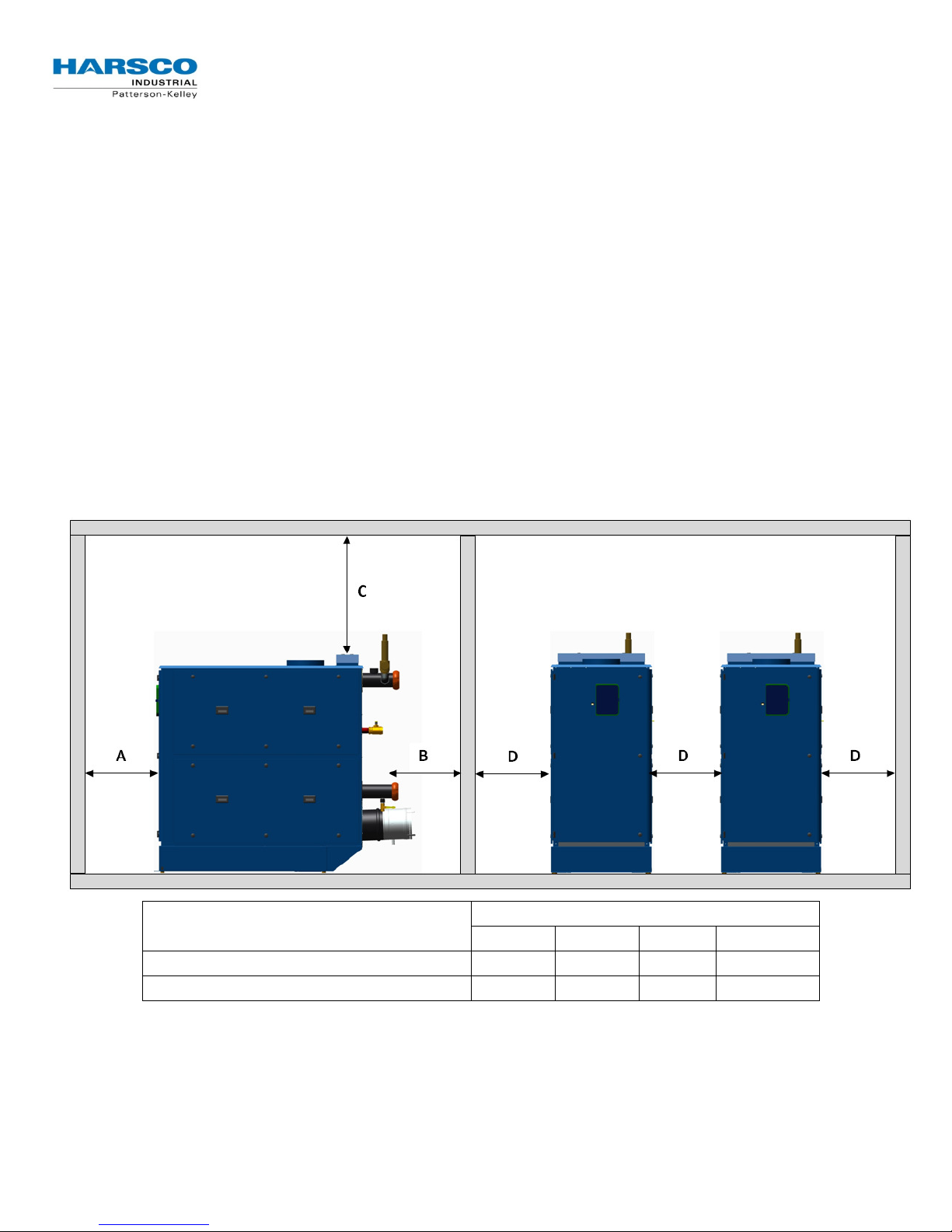
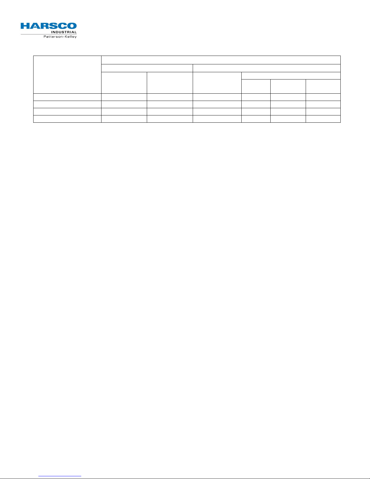
2.3.2 Clearances
If the boiler is to be installed near combustible surfaces, the inches minimum clearances are shown in the
illustration below. Failure to provide adequate service clearances, even with non-combustible surfaces, may
present problems during routine maintenance of the boiler. Maintain a clearance from the vent to combustible
surfaces of 24” or as specified in the vent manufacturer’s listed installation instructions. The boiler must be
installed in a space large in comparison to the boiler as described in the National Fuel Gas Code, NFPA
54/ANSI Z223.1, Latest Edition.
Type of Surface
CSA Minimum Clearances to Combustibles
Recommended Service Clearances
* “B” Clearance depends upon exhaust vent configuration.
† “C” Space required for pipes, ducts, etc. in this area above the boiler.
** Do not put pipes, ducts, vents, etc in this space. Electrical conduit must be installed vertically so that the side
doors can be opened.
Dimensions (inches)
A B C† D
30 12* 24† 12**
30 12* 24† 12**
P-K
SONIC
TM
Gas Fired Boiler
Boiler
Size Nom. vent
Stainless
V
ent
Boiler
Combustion
air
Size
Design and installation of
venting systems should be
done only be qualified and
knowledgeable venting systems
personnel and in accordance
with vent system
manufacturer’s installation
instructions. Installing a boiler
or vent system using improper
installation methods or
materials can result in serious
injury or death due to fire or
asphyxiation.
Before connecting a boiler to a
venting system, it must be
determined whether the boiler
is to be installed in a
conventional or direct vent
configuration. In the US,
provisions for combustion air
must be in accordance with
NFPA 54/ANSI Z223.1, National
Fuel Gas Code, latest edition,
or applicable provisions of
local building codes. In
Canada, combustion and
ventilation air openings shall
comply with CAN/CSA B-149.1
Natural Gas and Propane
Installation Code.
TTTTechnical Service 1.877.728.5351
echnical Service 1.877.728.5351
echnical Service 1.877.728.5351echnical Service 1.877.728.5351
2.4
Inlet Air and Exhaust Venting Considerations
2.4.1 Applicable Codes and Standards
United States:
NFPA 54/ANSI Z223.1 National Fuel Gas Code
NFPA/ANSI 211 Chimneys, Fireplaces, Vents and Solid Fuel Burning
Appliances
Canada:
CAN/CSA B149.1 Installation Codes for Gas Burning Equipment
Standards:
UL 1738 Venting Systems for Gas-Burning Appliances,
Categories II, III and IV
ULC S636-95 Standard for Type BH Venting System
Sheet Metal and Thermoplastic Duct Construction
Manual Air Conditioning Contractors National
Association (SMACNA)
These codes and standards contain information for the venting of gas
fired appliances, including, but not limited to vent sizing, location,
clearance to combustibles, and safe installation practices. The installation
must comply with both the above Federal Codes and with state, provincial
and local codes.
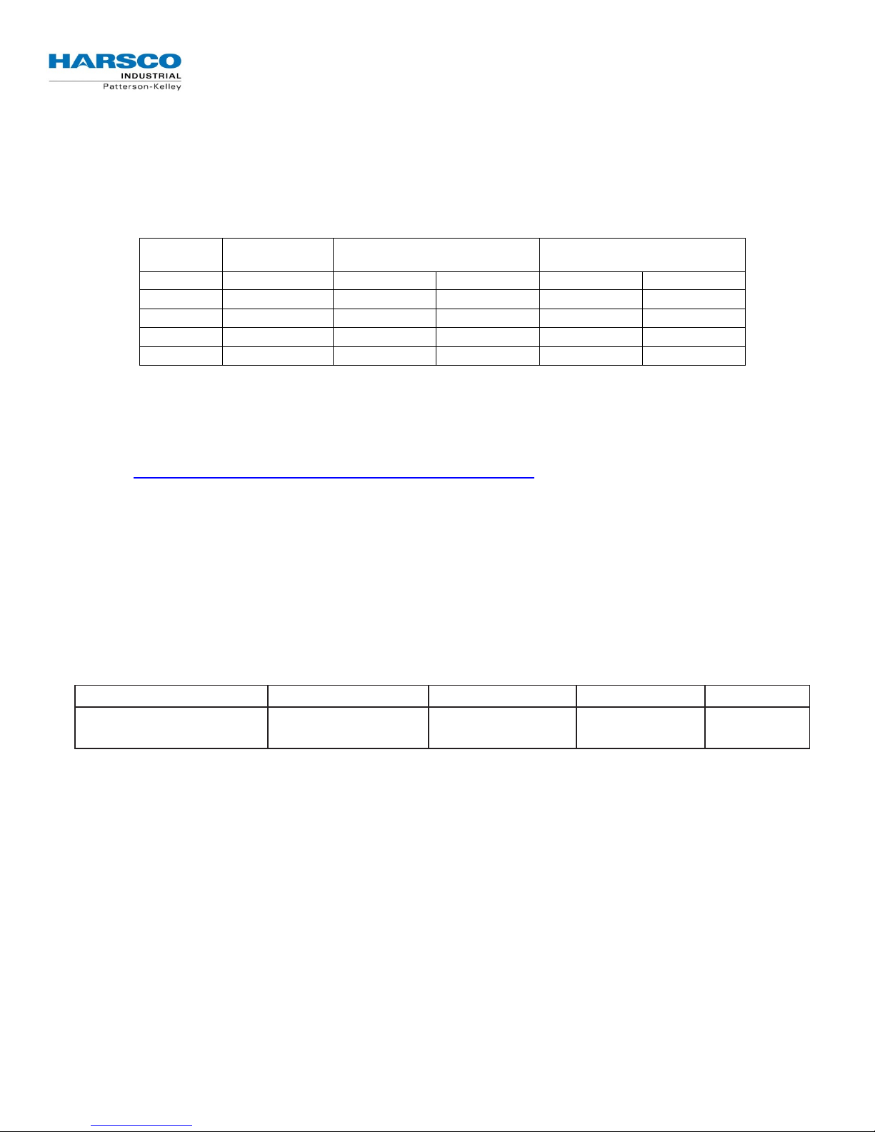
This table is for information only. Combustion air dampers
and vent adapters are listed for use of design and may or
may not be specific to your application.
Required Stainless Steel Vent Adapters and Category II Motorized Dampers
NOTE
Boiler Vent and Adapter Sizes
For correct installation of vent
system, read all of these
instructions and refer to vent
manufacturer’s instructions.
Failure to use a proper vent
system (types and materials),
as described in this manual will
void the boiler warranty and
may result in rapid deterioration
of the venting system, creating
a health or life safety hazard.
Faulty vent installation can
allow toxic fumes to be
released into living areas. This
may cause property damage,
injury or death.
Size
SC-1500 10” 2640000133
SC-2000 10” 2640000133
SC-3000 10” 2640000133
SC-4000 10” 2640000133
Vent Adapter
adapter
size
10” 12” 1004906946 12”
10” 12” 1004906946 12”
10” 12” 1004906946 12”
10” 12” 1004906989 14”
Combustion
Air inlet
N.C. Motorized
Damper
P-K
SONIC
TM
Gas Fired Boiler
TTTTechnical Service 1.877.728.5351
echnical Service 1.877.728.5351
echnical Service 1.877.728.5351echnical Service 1.877.728.5351
2.4.2 Gas Vent Category Planning
Several codes and standards have categorized appliances in accordance with the flue gas temperature and
pressure produced by the appliance. The applicable categories are defined as follows:
• Category II: An appliance that operates with a non-positive vent static pressure and with a vent
temperature that may cause excessive condensate production in the vent.
• Category IV: An appliance that operates with a positive vent static pressure and with a vent
temperature that may cause excessive condensate production in the vent.
• Direct Vent: An appliance that is constructed and installed so that all air for combustion is derived
directly from outdoors and all flue gases are discharged to the outdoors.
2.4.3 Air Inlet Planning (United States and Canada Considerations)
• Air inlet considerations for the United States are established by NFPA 54/ANSI Z223.1 & NFPA/ANSI
211.
• Air inlet requirements for the Canada States are established by CAN/CSA B149.1.
For details on the US air inlet requirements see Section 3.3.1 Air Inlet Requirements for more details.
2.4.4 Flue Venting Considerations
P-K SONIC TM boilers are dual certified as a Category II and Category IV appliances, as defined in ANSI
Z21.13/CSA 4.9, latest edition. The vent material to be used for US and Canada is listed in the Table of
Acceptable Materials for Venting Systems located in Section 2.4.5 Venting Materials for Flue/Exhaust
Systems. The exhaust vent can be run horizontally or vertically.
Vent installations shall be in accordance with NFPA54/ANSI Z223.1, the National Fuel Gas Code, or
CAN/
CSA-B149.1, the Natural Gas and Propane Installation Code, or applicable provisions of the local
building codes.
2.4.5 Venting Materials for Flue/Exhaust Systems
The P-K SONIC
appliances, which vents with a temperature that is likely to cause condensation
in the vent. Therefore, any venting system used with the P-K SONIC
must comply with the requirements for either Category II or Category IV venting
systems as specified in the latest edition of
the latest edition of
CPVC Venting
US: CPVC pipe conforming to ASTM F441. Sch 80 fittings
conforming to ASTM F439. Joints are to be sealed with solvent
conforming ASTM 493.
Canada: CPVC Pipe, Fitting and Sealant listed and
labeled to ULC S-636 Standard for Type BH Venting
Systems.
Polypropylene Venting
US and Canada: Polypropylene such as InnoFlue from
Centrotherm or PolyPro from DuraVent or other listed
manufacturers. When used, the same manufacturer's material
must be used throughout the system. It is not permissible to use
material from different manufacturers within the same system.
TM
boilers are dual certified as a Category II and Category IV
TM
CAN/CSA B-149.1
NFPA 54/ANSI Z223.1
in Canada.
in the US or
boiler
The venting materials listed are
intended for the venting of gas
burning appliances only. Do
not use these venting materials
for venting liquid or solid fuel
(such as oil, kerosene, wood or
coal) appliances.
Maintain clearances to
combustibles as listed in the
vent manufacturer’s
installation instructions or as
set forth in the codes and
standards listed in this section.
Do not use these vent pipes for
incinerators of any sort!
This boiler is not certified for
use with PVC venting. Use of
PVC venting may result in vent
failure and possible serious
injury or death.
P-K
SONIC
TM
Gas Fired Boiler
TTTTechnical Service 1.877.728.5351
NOTE 1:
echnical Service 1.877.728.5351
echnical Service 1.877.728.5351echnical Service 1.877.728.5351
As per ANSI Z21.13b-2012 * CSA 4.9b-2012:
• The use of cellular core PVC, CPVC and Radel as venting materials is prohibited.
• The use of external insulation on plastic vent pipe is prohibited.
Model Country AL29-4C 316L SS PVC CPVC POLYPROPYLENE
SC-1500 US Yes Yes No Yes Note 2
SC-2000 US Yes Yes No Yes Note 2
SC-3000 US Yes Yes No Yes Note 2
SC-4000 US Yes Yes No Yes Note 2
SC-1500 Canada Yes Yes No Note 1 Note 1
SC-2000 Canada Yes Yes No Note 1 Note 1
SC-3000 Canada Yes Yes No Note 1 Note 1
SC-4000 Canada Yes Yes No Note 1 Note 1
NOTE 2: When this material is
When this material is
used for venting, it must
be listed to ULC-S636.
used for venting, it must
be listed to UL-1738.
2.4.6 Required Clearances
2.4.6.1 Conventional Vent Systems Clearances
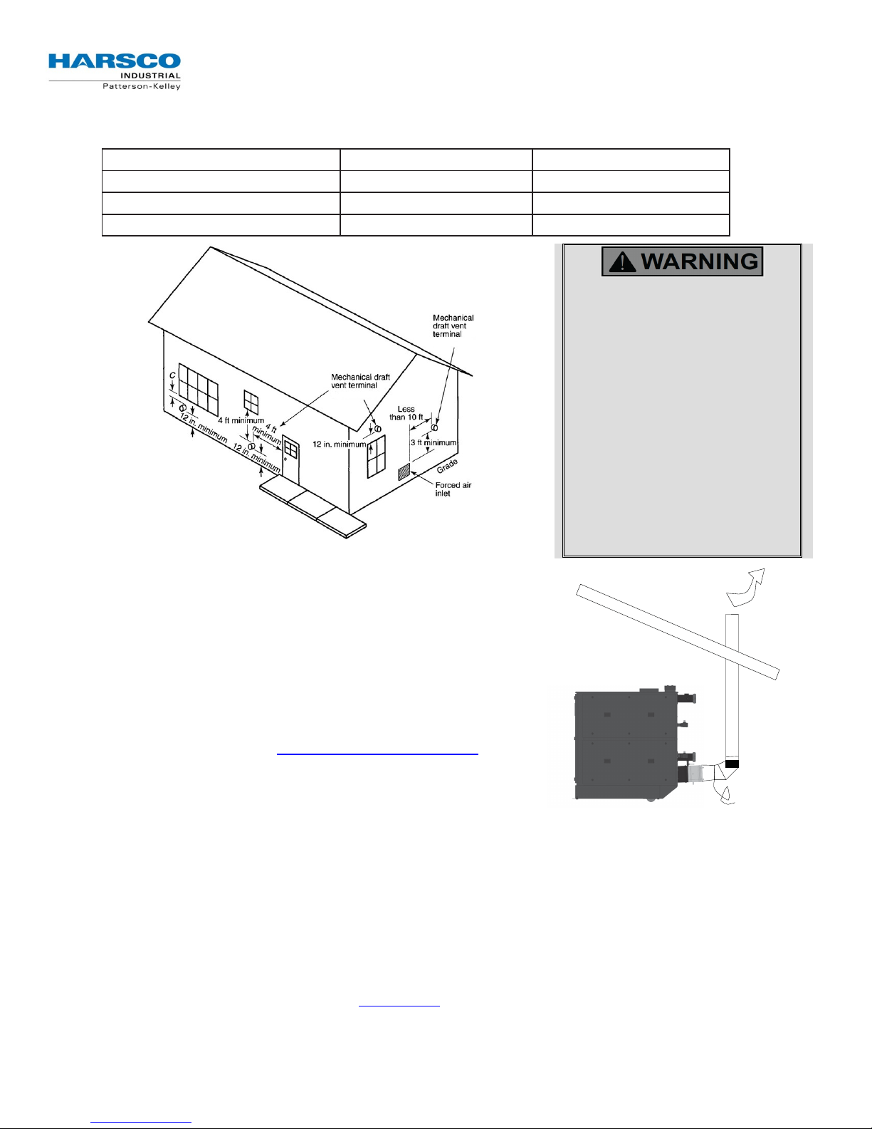
The following termination clearance requirements are for conventional non direct vent installations:
• The vent system shall terminate at least 3 ft. above a forced air inlet located within 10 ft. horizontally.
• The vent system shall terminate at least 4 ft . below, 4 ft. horizontally from or 1 ft. above any door,
operable window or gravity inlet into any building. The bottom of the vent terminal shall be at least 12
in. above grade or highest expected snow line (if applicable).
• Through the wall terminations shall not terminate over public walkways or over an area where
condensate or vapor could create a nuisance or hazard or could be detrimental to the operation of
regulators, relief valves or other equipment.
Acceptable Venting Materials
2.4.6.2 Direct Vent (Sealed Combustion) Systems Clearances
• The vent terminal shall be located at least 12 in. from any air opening into a building. The bottom of
the vent terminal shall be at least 12 in. above grade. Both the vent and air intake terminals must be
at least 12 in. above the highest expected snow line.
• Through the wall terminations shall not terminate over public walkways or over an area where
condensate or vapor could create a nuisance or hazard or could be detrimental to the operation of
regulators, relief valves or other equipment.
• When multiple direct vent appliances are adjacent, the exhaust must terminate at least 10 ft.
horizontally or 3 ft. vertically from the air intake of another appliance.
P-K
SONIC
TM
Gas Fired Boiler
TTTTechnical Service 1.877.728.5351
Material
echnical Service 1.877.728.5351
echnical Service 1.877.728.5351echnical Service 1.877.728.5351
2.4.6.3 Interior Component Clearances
All vent system components shall be installed so as to maintain the following required minimum clearances:
Combustible Non-Combustibles
Unlisted single wall metal pipe Do NOT Use Do NOT Use
Single wall PVC pipe Do NOT Use Do NOT Use
UL 1738 listed Category IV vent Per manufacturer’s listing Per manufacturer’s listing
Reference: NFPA 54/ANSI Z223.1 National Fuel Gas Code
NOTE
The condensate formed from combustion flue gases
are acidic. The condensate shall be drained in
accordance with local code. A condensate
neutralizer may be required by local code.
2.4.6.4 Flue Connection
The connection from the boiler to the vent should be as direct
as possible and the upward slope of any horizontal breaching
should be at least 1/4 inch per linear foot. The complete
exhaust with drain system is Section 3.4 Vent Termination.
The appliance connector should incorporate provisions to
drain condensate formed in the vent system. The connector
should include an appropriate drain section (not provided).
The boiler vent should not be
connected into any portion of
another mechanical draft system
without consulting the vent
manufacturer. The boiler shall
not be connected to any part of
a vent system serving a
Category I appliance, nor shall a
Category I appliance be
connected to any part of the
vent system serving this
appliance. For Category II
common venting, refer to local
venting codes. Improper
interconnection of venting
systems may result in leakage of
flue gases into occupied spaces.
2.5 Gas Piping Considerations
Before making the gas hook-up, make sure boiler is being supplied with the type of fuel shown on the boiler
nameplate. The boiler shall be installed such that gas ignition system components are protected from water
(dripping, spraying, rain, etc.) during appliance operation and service (circulator replacement, control
adjustment, etc.).
2.6 Water Quality Standard
The boiler’s heat exchanger is made of stainless steel. The heat exchanger requires proper water conditions
to remain efficient and function properly. For information refer to Harsco Industrial, Patterson-Kelley MultiMetal Systems Water Quality Standards in Appendix C, this applies to the warranty of your heat exchanger.

P-K
SONIC
TM
Gas Fired Boiler
TTTTechnical Service 1.877.728.5351
echnical Service 1.877.728.5351
echnical Service 1.877.728.5351echnical Service 1.877.728.5351
3 Installation
3.1 Overview
For site preparation follow the guidelines established in Section 2 Site Preparation. The information in this
section will partially copy some of the information in that section as a reminder of how important site
preparation is in the installation of the P-K SONIC
3.2 Electrical Connections
3.2.1 Power Requirements (CM300-CM399-CM500)
The SC-1500 and
operating amperage is indicated on the rating nameplate and the SC-1500 and SC-2000 requires less than
15 Amps at full load. Before starting the boiler, check to ensure that the proper electrical service is connected
to the boiler.
The
SC-3000
service OR
440-480VAC
the rating nameplate and the
the boiler, check to ensure that the proper electrical service is connected to the boiler.
and
SC-2000
SC-4000
boiler requires
208-240 VAC
boilers can be manufactured for
, three phase, 60 hertz electrical service. The total operating amperage is indicated on
SC-3000 & SC-4000
TM
boilers with NURO controls.
, single phase, 60 hertz electrical service. The total
208-240 VAC
, three phase, 60 hertz electrical
boilers require less than 20 Amps at full load. Before starting
NOTE
The SC-3000 & SC-4000 MUST be ordered to the correct voltage! IT IS NOT
POSSIBLE to convert an SC-3000 or SC-4000 between the 240V and 480V
configurations in the field.
An external electrical disconnect and overload protection (not supplied with the boiler) are required. Refer to
Section 6.1 for proper wiring and configuration of the electrical connections. The boiler electrical service must
be installed and grounded in accordance with local codes or in the absence of such requirements, in the U.S.
with National Electrical Codes, ANSI/NFPA No. 70 latest edition or, in Canada, to the current Canadian
Electrical Code, Part I, CSA C22.1 latest edition. Installed conduit must not block any of the boiler’s openings
and must allow the front door to be opened.
P-K
SONIC
TM
Gas Fired Boiler
TTTTechnical Service 1.877.728.5351
echnical Service 1.877.728.5351
echnical Service 1.877.728.5351echnical Service 1.877.728.5351
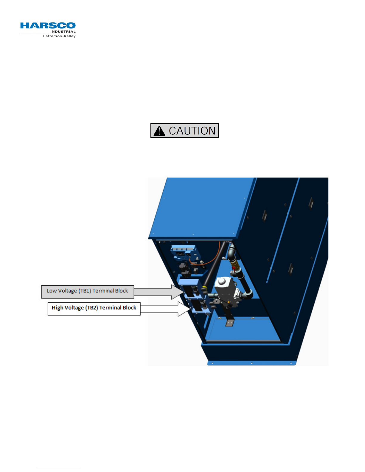
3.2.2 Single Phase Power Supply Connection (SC-1500 and SC-2000 Only)
The SC-1500 and SC-2000 must be supplied with 208-240VAC, single phase, 60 hertz electrical service. The
SC-1500 and SC-2000 feature four dedicated power terminals on the High Voltage (TB2) terminal block.
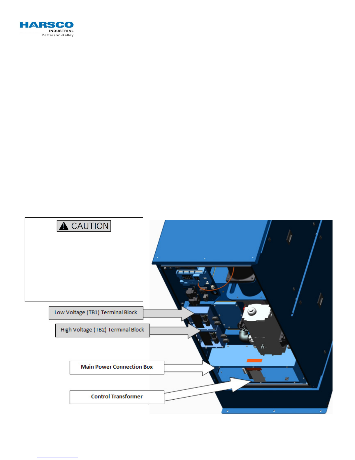
The illustration below shows the Low Voltage (TB1) and High Voltage (TB2) terminal blocks on the SC-
1500 and SC-2000 with the front door hidden for clarity:
• TB2 Terminal 1 = HOT L1
• TB2 Terminal 2 = HOT L2
• TB2 Terminal 3 = NEUTRAL
• TB2 Terminal 4 = GROUND
Do not over-tighten the terminal screws. Maximum tightening torque = 6 in-lbs!
NOTE
These terminals can accommodate maximum 10AWG wire.
P-K
SONIC
TM
Gas Fired Boiler
TTTTechnical Service 1.877.728.5351
echnical Service 1.877.728.5351
echnical Service 1.877.728.5351echnical Service 1.877.728.5351
3.2.3 Three Phase Power Supply Connection (SC-3000 & SC-4000 Only)
Main Power Connection Box
Check the rating nameplate of the SC-3000 or SC-4000 boiler to determine the required electrical service:
• 208-240VAC, three phase, 60 hertz
• 440-480VAC, three phase, 60 hertz
The incoming three phase power for the SC-3000 & SC-4000 boilers is connected to the over-current safety
device (rated for 20 Amps) and the Ground terminal located in the main power connection box. The
illustration below shows the Low Voltage (TB1) and High Voltage (TB2) terminal blocks, plus the Main Power
Connection Box on the SC-3000 & SC-4000 with the front door hidden for clarity:
• Terminal 1 = HOT L1
• Terminal 3 = HOT L2
• Terminal 5 = HOT L3
• Terminal G = GROUND
The Main Power Connection Box features a Control Transformer which steps down two hot leads from
the incoming three-phase power in order to supply 110-120VAC single phase power to the boiler’s control
system. Be aware that SC-3000 & SC-4000 boilers ordered in the 240V configuration, are pre-wired from the
factory for operation with 240 VAC three phase incoming power.
If 208 VAC three phase power is supplied to the boiler, the internal control transformer must be re-wired for
operation at this lower voltage. The wire in terminal X3 on the load side of the internal control transformer
must be moved to terminal X4. This supplies the 120 VAC power to the controls from the 208 VAC main
voltage. Refer to Section 6.1 for proper wiring and configuration of the internal control transformer.
Do not over-tighten the hot lead
terminal screws. Maximum tightening
torque = 13 in-lbs!
NOTE
The hot lead terminals can
accommodate maximum 12AWG wire.
The ground terminal can
accommodate maximum 8 AWG wire.
P-K
SONIC
TM
Gas Fired Boiler
TTTTechnical Service 1.877.728.5351
3.2.4
High
Voltage
(TB2)
T
erminal
Block
echnical Service 1.877.728.5351
echnical Service 1.877.728.5351echnical Service 1.877.728.5351
Be sure to check the
nameplate on the boiler
before connecting the
electrical supply.
N
OTICE!
A dedicated earth ground
(green wire) is required to avoid
nuisance shutdowns. Do not
ground through the conduit!
The high voltage (TB2)
terminal block on the SONIC
SC-1500 and SC-2000 with
NURO controls contains two
hot leads (HOT L1 & HOT L2),
a neutral lead (NEUTRAL) and
a ground lead (GROUND) for
208- 240 VAC, single phase
60Hz electrical supply. This
terminal block (TB2) also
contains dry-contact relays
with a maximum voltage
rating of 240VAC and 1/2 Amp
maximum current capacity.
Incorrect wiring can result in
equipment damage, injury or
death.
The high voltage (TB2)
terminal block on the SONIC
SC-3000 & SC-4000 with
NURO controls contains dry-
contact relays with a
maximum voltage rating of
240VAC and 1/2 Amp
maximum current capacity.
Incorrect wiring can result in
equipment damage, injury or
death.
Start Interlock #2 –
The Start Interlock #1 terminals can be used for
auxiliary safety devices such as damper end limit switches, control valve
end limit switches, emergency stop buttons, and low water cutoff devices.
This circuit is energized with
safety devices must be rated for a minimum of
Start Interlock #1 –
The Start Interlock #2 terminals are in series with
120VAC
, so the contacts on any auxiliary
120VAC
.
Start Interlock #1 and provide additional connection points for auxiliary
safety devices. This circuit is energized with
any auxiliary safety devices must be rated for minimum
120VAC
, so the contacts on
120VAC
.
The boiler ships with a factory-installed jumper across Start Interlock #1
and Start Interlock #2 terminals. Remove the jumper(s) if using any
auxiliary safety devices
.
NOTE
Both the Start Interlock #1 and Start Interlock #2 circuits
must close within 5 minutes of a call for heat. Failure to
close the Start Interlock circuit will cause the boiler to
lockout on alarm
Auxiliary Input #2 –
circuit is energized with
Auxiliary Input #1 –
circuit is energized with
.
These terminals are reserved for future use. This
120VAC
.
These terminals are reserved for future use. This
120VAC
.
Air Damper Interlock – The Air Damper Interlock provides dedicated
terminals for proof of open end limit switch on a motorized air damper.
This circuit is energized with 120VAC, so the contacts on the end limit
switch must be rated for minimum 120VAC.
The boiler ships with a factory-installed jumper across the Air
Damper Interlock terminals. Remove the jumper if connecting a
motorized air damper with end limit switch.
Relay A – User-configurable relay output #1. The normally-open contacts
on this relay have a maximum voltage rating of 240VAC and maximum
current capacity of 1/2 Amp.
Relay B – User-configurable relay output #2. The normally-open contacts
on this relay have a maximum voltage rating of 240VAC and maximum
current capacity of 1/2 Amp.
Relay C –
User-configurable relay output #3. The normally-open contacts
on this relay have a maximum voltage rating of 240VAC and maximum
current capacity of 1/2 Amp.
Relay D –
User-configurable relay output #4. The normally-open contacts on this relay have a maximum
voltage rating of 240VAC and maximum current capacity of 1/2 Amp.

P-K
SONIC
TM
Gas Fired Boiler
TTTTechnical Service 1.877.728.5351
echnical Service 1.877.728.5351
echnical Service 1.877.728.5351echnical Service 1.877.728.5351
NOTE
Refer to Section 6 Parts and Tech Support for proper wiring and configuration of
the electrical connections.
Relays A thru D can be user-configured through the NURO touch screen
interface to control devices such the Comfort Heat (CH) Pump, Domestic Hot
Water (DHW) Pump, Air Damper, System Pump, etc.
Master Alarm Relay – The Master Alarm Relay terminals are normally-open dry contacts that close in the
event of an alarm output from the boiler control.
3.2.5 Low Voltage (TB1) Terminal Block
Enable/Disable –
TB1-1
and
TB1-2
can be used to remotely enable or disable the boiler. The functionality of
these terminals is user-configurable through the NURO controls, but generally closure of the Enable/Disable
circuit provides a call for heat to the boiler. Opening this circuit prevents the boiler from running.
The boiler ships with a factory-installed jumper across the Enable/Disable terminals. This circuit is energized
with a
4-20mA Analog Input –
24VAC
potential, so the contacts on any remote enable devices must be rated for minimum
TB1-3
and
TB1-4
can be used to provide a remote analog 4-20mA control signal to
24VAC
.
the boiler. This analog signal can be used to change the boiler’s operating setpoint or firing rate.
Spare Analog Input –
HDR Temp Sensor –
TB1-5
TB1-7
and
and
TB1-6
TB1-8
are reserved for future use.
can be used to connect a remote header temperature sensor,
installed in the primary hydronic system piping, downstream of all the boilers. This temperature sensor must
be a 2-wire 12kΩ NTC thermistor. This circuit is energized by the boiler with a
DHW Stat/Sensor –
TB1-9
and
TB1-10
can be used to connect either an aquastat or remote DHW
5VDC
potential.
temperature sensor installed in a domestic hot water storage tank. If using an aquastat, use a SPST
normally-closed, break on rise type with either a fixed or adjustable deadband above and below the setpoint.
Alternatively, if using a temperature sensor, it must be a 2-wire 12kΩ NTC thermistor and be of sufficient
length to measure an accurate storage tank temperature. This circuit is energized by the boiler with a
5VDC
potential.
Outdoor Temp Sensor –
TB1-11
and
TB1-12
can be used to connect an outdoor air temperature sensor which
allows the NURO control to be programmed to run an outdoor air schedule. The outdoor air temperature sensor
must be a 2-wire 12kΩ NTC thermistor and should be installed on the North face of the building and shielded
from direct sunlight exposure. This circuit is energized by the boiler with a
5VDC
potential.
Night Setback –
TB1-13
and
TB1-14
Night Setback circuit enables the Night Setback mode which reduces the boiler’s operating setpoint. Opening
this circuit resumes normal operation. This circuit is energized by the boiler with a
contacts on the day/night timer must be rated for minimum
4-20mA Analog Output –
TB1-15
firing rate. When operating at full power (maximum firing rate), the boiler will provide a 20mA output. When
operating at minimum power (minimum firing rate), the boiler will provide a 4mA output.
Ground –
TB1-17
provides an equipment (frame) ground connection for input, output, or communication
connections. For independently powered control devices, it may be necessary to create a common ground.
can be used to connect a day/night or occupancy timer. Closure of the
5VDC
potential, so the
5VDC
.
and
TB1-16
provide a 4-20mA analog output signal which tracks the boiler’s
P-K
SONIC
TM
Gas Fired Boiler
TTTTechnical Service 1.877.728.5351
Cascade Shield & Cascade –
multiple SONIC boilers with NURO controls. Terminals
TB1-18, TB1-19
and
TB1-20
TB1-19
can be used to setup a cascade system with
and
communication between the master and member boilers. Terminal
echnical Service 1.877.728.5351
echnical Service 1.877.728.5351echnical Service 1.877.728.5351
TB1-20
TB1-18
are reserved for the cascade
should be used to connect the
cascade communication wiring shield between all boilers. The cascade and shielding must be wired from the
master boiler to each individual member boiler in a daisy-chain fashion. NOTE: Only ground the shield at the
master boiler.
MODBUS COM & MODBUS Shield –
TB1-22, TB1-23
and
TB1-24
can be used to integrate the boiler with a
Building Management System (BMS), Protocol Converter, or other device capable of RS-485 2-wire
MODBUS communication. Terminals
TB1-22
and
TB1-23
are reserved for MODBUS and terminal
TB1-18
provides a connection for the MODDBUS communication wire shield. NOTE: Only ground the shield at the
master boiler.
ECOM 1, 2 & 3 –
TB1-25, TB1-26
and
TB1-27
can be used to connect a wireless outdoor air temperature
sensor. The wireless receiver should be installed at or near the boiler, and the wireless temperature sensor
should be installed on the North face of the building and shielded from direct sunlight exposure.
3.3 Combustion Air
The air intake duct can be fabricated from PVC, CPVC, single wall galvanized steel, or other suitable
materials. The duct must be rigid enough to maintain the full required cross sectional area under all operating
conditions. Proper sealing of the intake ductwork is necessary to prevent infiltration of air from conditioned
space. Joints in PVC or CPVC must be cemented. For galvanized duct, wrap each joint and seam with
adhesive aluminum tape or other sealant. The installation of a bird screen on the intake termination is
recommended. Ensure that the screen does not become blocked with snow, ice, insects etc. Combustion air
duct should be designed with maximum 0.22” w.c. friction loss.
Combustion air must be free from dust, lint, etc. The presence of such materials in the air supplied to the
burner could cause nuisance "Low Air" shutdowns or premature burner failure. The boiler should not be
operated during construction while the possibility of drywall dust, demolition dust, etc. exists.
The combustion air supply must be completely free of chemical fumes which may be corrosive when burned
in the boiler. Common chemicals which must be avoided are fluorocarbons and other halogenated
compounds, most commonly present as refrigerants or solvents, such as Freon®, trichloroethylene,
perchloroethylene, chlorine, etc. These chemicals, when burned, form acids which quickly attack the boiler
and the boiler stack. The result is improper combustion and premature boiler failure.
Refer to the table below which summarizes the combustion air requirements for the SONIC boilers. Ensure
the combustion air piping is of sufficient size (and acceptable equivalent length) in order to carry the required
SCFM with a maximum friction loss of 0.22”
P-K SONIC™
Boiler Model
SC-1500
SC-2000
SC-3000
SC-4000
W.C.
Required SCFM
350
467
629
839
Acceptable Materials for Venting Systems
Manufactured Venting Systems
US and Canada:
AL29-4C Stainless Steel Vent Systems listed and labeled to UL1738 Venting Systems for GasBurning Appliances, Categories II, III, and IV
316L Stainless Steel where certified and warranted by the vent manufacturer for venting of Category
II, III, or IV appliances
P-K
SONIC
TM
Gas Fired Boiler
TTTTechnical Service 1.877.728.5351
3.3.1.2
US Requirements
echnical Service 1.877.728.5351
echnical Service 1.877.728.5351echnical Service 1.877.728.5351
3.3.1 Air Inlet Requirements
3.3.1.1 United States Considerations
When air is supplied from inside the building, the total required volume shall be the sum of the required volume
for all the appliances located in the mechanical room. Adjacent rooms furnished with fixed openings
communicating directly with the mechanical room are considered part of the required volume. The minimum
volume is 50 ft
Openings used to connect indoor spaces to obtain the required minimum volume shall be sized as follows:
• When rooms are on the same floor, each opening shall have an area equal to 1 square inch for each 1000
Btu/hr (2200 mm2/kW) of installed appliance input capacity, but not less than 100 square inches. One
opening should commence less than 12 inches above the floor and the other less than 12 inches below
the ceiling. The minimum dimension of air openings shall be 3 inches.
• When rooms are on different floors, each opening shall have an area equal to 2 square inches for each
1000 Btu/hr (4400 mm2/kW) of installed appliance input capacity.
When combustion air is supplied from outside the building, the boiler room shall be provided with one or two
openings to ensure adequate combustion air and proper ventilation.
When using one permanent opening, the opening shall commence within 12 inches of the ceiling and shall
communicate directly with the outdoors or through a vertical or horizontal duct that communicates to the outdoors.
Minimum free area of the opening is 1 square inch for each 3000 Btu/hr (700 mm2/kW) of installed appliance input
capacity, and not less than the sum of the areas of all vent connectors in the room.
3
per 1000 Btu/hr (4.8 m3/kW) of installed appliance input capacity.
Under no circumstances
shall the boiler room ever
be under a negative
pressure.
Particular care should be
taken when exhaust fans,
compressors, air-handling
units or other equipment
may rob air from the boiler.
Note that this equipment
might be in rooms other
than the boiler room. This
applies to both sealed
combustion and
atmospheric room
combustion air applications.
Air inlet requirements for the United States are established by NFPA
54/ANSI Z223.1 & NFPA/ANSI 211.
openings, one opening shall commence within
When using two permanent
12 inches above the floor
and the other within 12 inches below the ceiling, preferably on opposite
walls. The openings shall communicate directly, or by way of ducts, with
free outdoor air. The minimum net free area of the openings shall be
calculated in accordance with the following:
• When air is taken directly from outside the building, each
opening (minimum of two, as outlined above), 1 square inch for
each 4,000 Btu per hour (550 mm2/kW) of total boiler input is
required.
• When air is taken from the outdoors through a vertical duct into
the mechanical room, 1 square inch per 4,000 Btu per hour (550
mm2/kW) of total boiler input is required.
• When air is taken from the outdoors through a horizontal duct
into the mechanical room, 1 square inch per 2,000 Btu per hour
(1100 mm2/kW) of total boiler input is required.
P-K
SONIC
TM
Gas Fired Boiler
TTTTechnical Service 1.877.728.5351
TWO OPENINGS
DIRECT
VERT
HORIZ
echnical Service 1.877.728.5351
echnical Service 1.877.728.5351echnical Service 1.877.728.5351
US Minimum Area of Ventilation Openings per Boiler (Sq In)
AIR SOURCE
SONIC TM Boiler
MODEL
SC-1500 1500 3000 500 375 375 750
SC-2000 2000 4000 667 500 500 1000
SC-3000 3000 6000 1000 750 750 1500
SC-4000 4000 8000 1334 1000 1000 2000
INDOOR AIR SUPPLY OUTDOOR AIR SUPPLY
SAME
FLOOR
DIFF
FLOORS
ONE
OPENING
3.3.1.3 Canadian Considerations
Air inlet requirements for the Canada States are established by CAN/CSA B149.1.
NOTE
1. The free area of a combustion air supply opening is calculated by deducting the
blockage area of any fixed louvers, grilles or screens from the total area of the
opening.
2. Screens shall be not smaller than ¼ inch.
3. Motorized louvers shall be interlocked with the appliance so that they are proven
open prior to main burner ignition and operation.
DUCT
DUCT
A. A. Ventilation of the space occupied by fuel burning appliance(s) or equipment shall be supplied by a
ventilation opening at the highest practicable point communicating with the outdoors. The total cross
sectional area of the ventilation opening must be either 10% of the net free area required for
combustion air or 10 sq. in. (6500 mm2), whichever is greater.
B. Use the following opening calculation for P-K SONIC TM boilers:
When combustion air is supplied for a forced draft burner by natural airflow from the outdoors and
there is no draft regulator or draft hood in the same space, there shall be a permanent opening with a
cross sectional area not less than 1 sq. in/30,000 Btu/Hr (70 mm2/kW) of the total rated input to the
burner(s). This opening must not interfere with the ventilation air opening defined in paragraph A.
C. Use the following opening calculation for
P-K THERMIFIC®
boilers or other natural draft or fan-assist
appliances:
When combustion air is supplied for natural or fan-assisted burners by natural airflow from the
outdoors, there shall be a permanent opening with a cross sectional area not less than 1 sq. in/7000
Btu/Hr (321 mm2/kW) up to and including 1,000,000 Btu/Hr plus 1 sq. in./14,000 Btu/Hr (155 mm2/kW)
in excess of 1,000,000 Btu/Hr. This opening must be either located at or ducted to a point not more
than 18 in. (450 mm) or less than 6 in. (150 mm) above floor level. This opening is in addition to the
ventilation air opening defined in paragraph A.
D. When combustion air is supplied by natural airflow into a space containing both types of appliance
described in paragraphs B and C, the cross sectional area of the opening shall not be less than the
sum of the cross sectional areas for all appliances in the space as calculated by the applicable
method. This opening is in addition to the ventilation air opening defined in paragraph A.
E. When a duct is used to meet the requirement for combustion air supply, as described in paragraphs A
through D, above, the opening of the duct shall be located so there is no possibility of cold air
affecting steam or water piping, electrical equipment or mechanical equipment.
P-K
SONIC
TM
Gas Fired Boiler
TTTTechnical Service 1.877.728.5351
SONIC
TM
Required Combustion Air
CO2 Natural Gas
echnical Service 1.877.728.5351
echnical Service 1.877.728.5351echnical Service 1.877.728.5351
F. When combustion air is supplied by mechanical means, an airflow-sensing device must be installed. It
must be wired into the pre-ignition limit c to prevent the burner from starting or to stop an operating
burner in case of air supply failure.
G. When all combustion air is supplied through a make-up air heater, and the appliance is interlocked to
the heater, the requirements of paragraphs A through F do not apply.
Canadian Minimum Area of Combustion and Ventilation Air Openings
Boiler
Model # Input in2 mm2 in2 mm2
SC-1500 1,500,000
SC-2000 2,000,000
SC-3000 3,000,000
SC-4000 4,000,000
BTU/Hr
Opening
50 32,258 10 6,452
67 43,226 10 6,452
100 64,516 10 6,452
134 86,451 13.4 6,452
Ventilation Air Opening
3.3.2 Flue Venting Installation
This boiler is not certified for use with Type "B" vent nor with
certified as a Category II and Category IV appliances, as defined in
PVC
venting. All P-K SONIC
ANSI Z21.13/CSA 4.9
vent material to be used for US and Canada is listed in the Table of Acceptable Materials for Venting Systems
located in Section 2.4.5 Venting Materials for Flue/Exhaust Systems. The exhaust vent can be run
horizontally or vertically.
Vent installations shall be in accordance with NFPA54/ANSI Z223.1, the National Fuel Gas Code, or CAN/
CSA-B149.1, the Natural Gas and Propane Installation Code, or applicable provisions of the local building
codes.
3.3.2.1 Vent Sizing
The vent must be sized in accordance with the
ASHRAE
Systems and Equipment handbook, Chapter 30 or
according to the vent manufacturer’s recommendations. When using manufactured venting systems, consult
your vent supplier for correct sizing and structural support requirements. See the below table for vent design
parameters
TM
boilers are dual
, latest edition. The
P-K SONIC™ Boiler Model Frictional Resistance Stack Temperature
SC-1500, SC-2000, SC3000, SC-4000
0.22” wc 220 °F 9.2% 10.4%
CO2 LP Gas
 Loading...