

Harsco Industrial P-K THERMIFIC N700, P-K THERMIFIC N1000, P-K THERMIFIC N1500, P-K THERMIFIC N1700, P-K THERMIFIC N2000 Installation & Owners Manual

P-K THERMIFIC®
GAS-FIRED BOILER
Model#: __________________________
Serial#: __________________________
Start-up Date: __________________________
Harsco Industrial, Patterson-Kelley
100 Burson Street
East Stroudsburg, PA 18301
Telephone: (570) 476-7261
Fax: (570) 476-7247
www.harscopk.com
©1989-2012 Harsco Industrial, Patterson-Kelley
Printed 11/4/2011
THERM201_2-19-12

P-K THERMIFIC
®
Gas-Fired Boiler
2

P-K THERMIFIC
®
1 INTRODUCTION ....................................................................................... 5
2 SAFETY ..................................................................................................... 5
2.1 General ....................................................................................................... 5
2.2 Training ....................................................................................................... 5
2.3 Safety Features ........................................................................................... 6
2.4 Safety Labels .............................................................................................. 6
2.5 Safety Precautions ...................................................................................... 7
3 INSTALLATION ......................................................................................... 9
3.1 Receiving and Storage ................................................................................ 9
3.2 Compliance with Codes .............................................................................. 9
3.3 Setup ......................................................................................................... 10
3.4 Electrical Connections .............................................................................. 11
3.5 Inlet Air and Exhaust Venting .................................................................... 11
3.6 Gas Piping ................................................................................................ 26
3.7 Boiler Water Piping ................................................................................... 29
3.8 Pre-Start Check List .................................................................................. 33
3.9 Safety Checks ........................................................................................... 34
3.10 Initial Adjustments ..................................................................................... 35
Gas-Fired Boiler
4 OPERATION ............................................................................................ 43
4.1 General ..................................................................................................... 43
4.2 Lighting and Shut-Down Procedures ........................................................ 43
4.3 Typical Boiler Operating Conditions .......................................................... 44
5 MAINTENANCE ....................................................................................... 45
5.1 Maintenance and Inspection Schedule ..................................................... 45
5.2 Cleaning the Burner .................................................................................. 47
5.3 Removing the Exchanger .......................................................................... 48
5.4 After All Repairs or Maintenance .............................................................. 48
5.5 Sequence Of Operation ............................................................................ 49
5.6 Troubleshooting ........................................................................................ 50
6 PARTS/TECHNICAL SUPPORT ............................................................. 51
6.1 Wiring Diagrams ....................................................................................... 51
6.2 Boiler Parts List ......................................................................................... 59
7 LIMITED WARRANTY ............................................................................. 63
3
P-K THERMIFIC
®
Gas-Fired Boiler
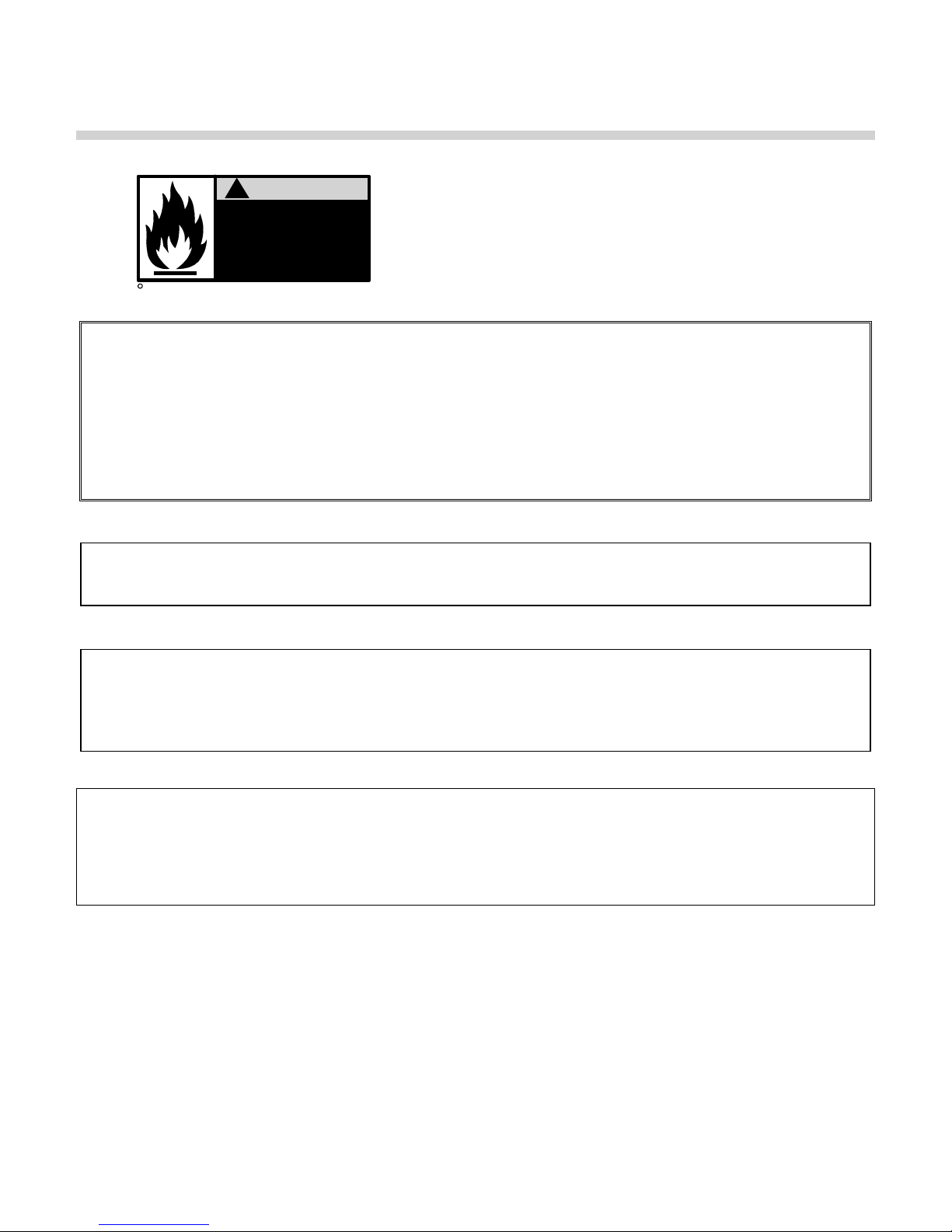
!
WARNING
Improper use may
result in fire or injury.
Read instructions/safety
manual before installing,
c
1998 HCS, Inc. 800-748-0241
If the information in this manual is not followed exactly, a fire or explosion may result causing property
damage, personal injury or loss of life.
Do not store or use gasoline or other flammable vapors or liquids in the vicinity of this or any other
appliance.
Installation and service must be performed by a qualified installer, service agency, or the gas supplier.
operating or servicing boiler.
Reorder No. 6020-V2WHPK
It is essential to read, understand, and follow the recommendations of this
manual before installing, operating, or servicing this equipment.
Installation and service must be performed by a qualified and knowledgeable
individual who has been trained on the P-K THERMIFIC® boiler. The same features which permit this
boiler to achieve high-efficiency performance make it unlike most other boilers of this general size, so it
is important to understand how this boiler operates.
What to do if you smell gas:
Do not try to light any appliance.
Do not touch any electrical switch; do not use any phone in your building.
Immediately call your gas supplier from a neighbor's phone. Follow the gas supplier's instructions.
If you cannot reach your gas supplier, call the fire department.
4

P-K THERMIFIC
®
Gas-Fired Boiler
1 INTRODUCTION
The P-K THERMIFIC® gas-fired boiler combines a radial pre-mix fan-assisted burner with a compact,
finned-tube heat exchanger to provide maximum efficiency in a minimum of space. The high-quality
materials and thoroughly tested design of the boiler should provide years of trouble-free, hot-water
service, if the instructions in this manual are followed carefully.
This manual covers installation of P-K THERMIFIC
®
boilers. The model numbers may be followed by a
prefix or suffix letter in some cases to indicate special features or different options.
While details may differ slightly, basic operation is the same for all models. Boilers may be built to
operate with natural gas or liquefied petroleum gas (propane). Check the rating plate for correct fuel
usage and gas pressures.
The boiler is only a part of the complete heating system. This boiler may be fully operational and yet
because of poor circulation, control or other operating characteristics, not deliver heat to the desired
location. Additional equipment such as temperature sensors, pumps, flow switches, balancing valves
and check valves will be required for satisfactory operation of any system. Harsco Industrial,
Patterson-Kelley cannot be responsible for the design or operation of such systems and a qualified
engineer or contractor must be consulted.
2 SAFETY
2.1 GENERAL
The P-K THERMIFIC gas-fired boiler must be:
Installed, operated, and serviced in accordance with instructions contained in this manual.
Installed by qualified personnel in accordance with designs prepared by qualified engineers including:
structural, mechanical, electrical, and other applicable disciplines.
Operated and serviced in accordance with a comprehensive safety program determined and estab-
lished by the customer. Do not attempt to operate or service until such a program has been estab-
lished.
Operated and serviced by experienced, qualified, properly trained personnel in accordance with all
applicable codes, laws, and regulations.
NOTICE! Each safety device must be maintained and checked per the recommended schedule. Refer
to Section 5.1 of this manual.
2.2 T
RAINING
It is essential to read, understand, and follow the
recommendations of this manual before installing,
operating, or servicing this equipment. Failure to do
so could result in fire or explosion and serious injury,
death, and/or property damage. Proper training is
the best protection against accidents.
5
P-K THERMIFIC
®
Gas-Fired Boiler
Operating and service personnel must be thoroughly familiar with the basic construction of the
P-K THERMIFIC
its various mechanisms, and all applicable safety precautions. If any of the provisions of this manual are
not fully and completely understood, contact the Harsco Industrial, Patterson-Kelley Technical Service
Department toll-free at (877) 728-5351 for assistance.
2.3 S
AFETY FEATURES
It is the responsibility of the customer to maintain the safety features of this appliance, such as but not
limited to: guards, safety labels, safety controls, interlocks and lockout devices.
2.4 S
AFETY LABELS
The following words are used in this manual to denote the degree of seriousness of the individual
hazards.
in death or serious injury. This signal word is to be limited to the most extreme situations.
boiler, the use and locations of the controls, the operation of the boiler, adjustment of
indicates an imminently hazardous situation which, if not avoided, will result
indicates a potentially hazardous situation which, if not avoided, could result
in death or serious injury.
indicates a potentially hazardous situation which, if not avoided, may result in
minor or moderate injury. It may also be used to alert against unsafe practices.
NOTICE/NOTE: - NOTICE is the preferred signal word to address practices not related to personal
injury. The safety alert symbol is not used with this signal word.
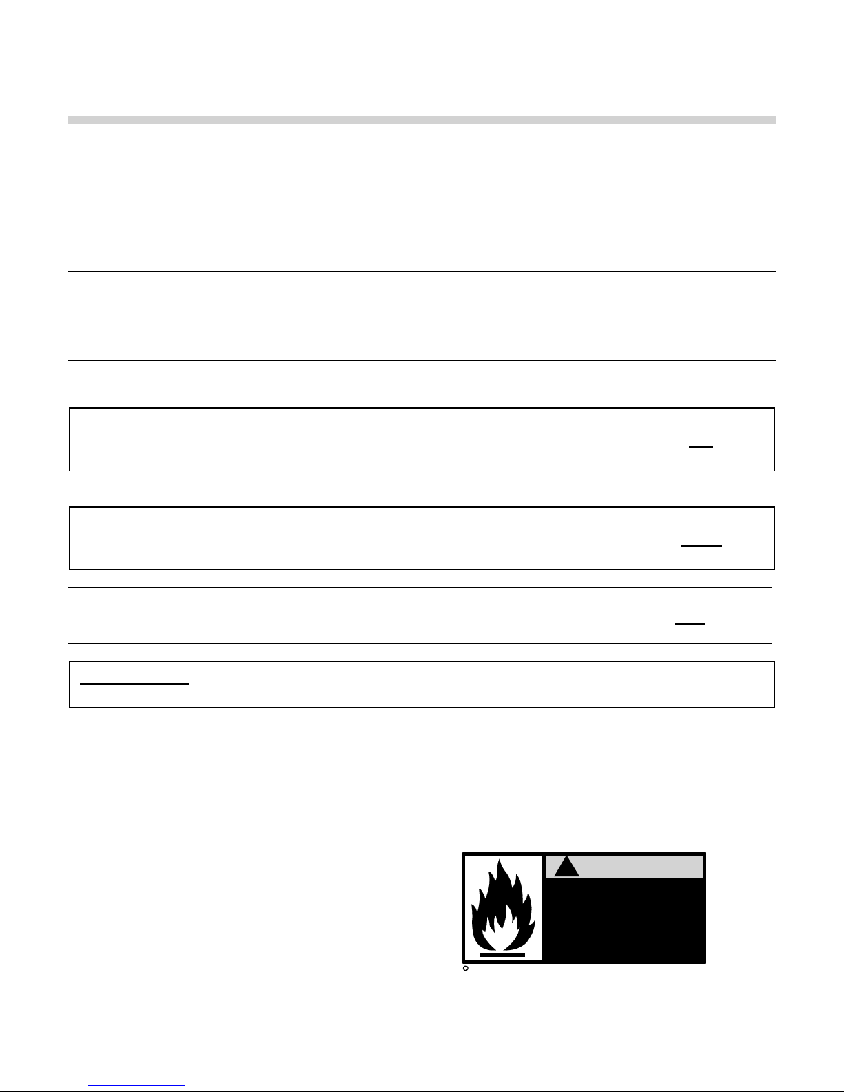
!
c
1998 HCS, Inc. 800-748-0241
WARNING
Improper use may
result in fire or injury.
Read instructions/safety
manual before installing,
operating or servicing boiler.
Reorder No. 6020-V2WHPK
6
P-K THERMIFIC
®
Gas-Fired Boiler
The safety labels shown above are affixed to your boiler. Although the labels are of high quality, they
may become dislodged or unreadable over time. Contact Harsco Industrial, Patterson-Kelley toll-free at
(877) 728-5351 for replacement labels.
2.5 S
Provide a suitable location for the boiler, away from normal personnel traffic, with adequate working
space, adequate clearances, proper ventilation and lighting, with a structure sufficiently strong and rigid
to support the weight of the boiler, all piping, and accessories.
2.5.1 Electrical Hazards
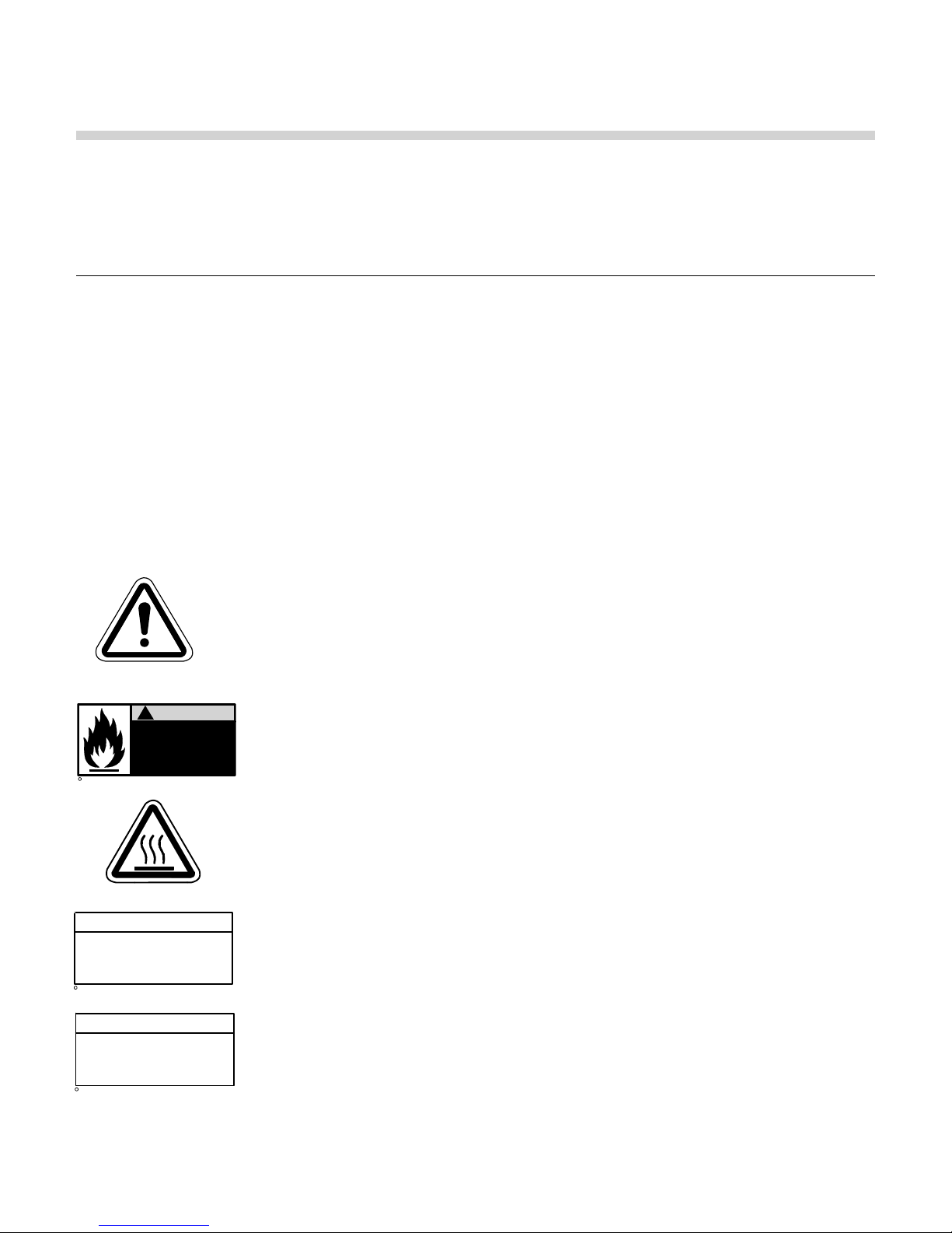
2.5.2 Burn, Fire, and Explosion Hazards
c
1998 HCS, Inc. 800-748-0241
AFETY PRECAUTIONS
General Warning
!
WARNING
Improper use may
result in fire or injury.
Read instructions/safety
manual before installing,
operating or servicing boiler.
Reorder No. 6020-V2WHPK
Shock hazard! Properly lockout/tagout the electrical service and
all other energy sources before working on or near the boiler.
Shock hazard! Boiler is not rated for wash-down service. Do not
spray water directly on this boiler or on any electrical components.
Electrical Hazard! Do not alter wiring connections.
Burn, fire, and explosion hazards! Installation must be in strict conformance to
all applicable codes and standards including NFPA 54, ANSI Z223.1 and
CAN/CGA B.149, latest edition. Install all required vent lines for gas devices.
Refer to Section 3.6.2 below.
Hazard from incorrect fuels! Possible fire, explosion, overheating, and
damage. Do not use any fuels except the design fuel for the unit.
Over fire hazards! High pressure in gas or propane supply could result in over
firing of other devices supplied from the same source.
Fire and explosion hazards! Close the main gas shutoff before servicing
boiler.
Fire and explosion hazards! Do not store or use gasoline or other flammable
vapors or liquids in the vicinity of this or any other gas fired appliance.
Hot Surface
NOTE
Make sure this union is
tight before closing cabinet
cover after servicing boiler.
c
1998 HCS, Inc. 800-748-0241
Reorder No. 8032-02NHAK
Burn hazard! Possible hot surfaces. Do not touch the exhaust vent during
firing operation. Use only factory recommended vent components.
Burn hazard! Pipes, vents, and boiler components could be hot. Do not touch
piping or exhaust vent surfaces during operation or immediately after
shutdown of the boiler.
Burn hazard! Hot fluids. Allow boiler to cool before servicing or draining
NOTE
When opening leak test valves,
always follow instructions in
operation and safety manual.
c
1998 HCS, Inc. 800-748-0241
Reorder No. 8032-01NHPK
boiler.
Fire and explosion hazards! Use caution when servicing burner. Propane
(LPG) is heavier than air and may linger in the combustion chamber, vent
lines, or elsewhere.
7
P-K THERMIFIC
®
Gas-Fired Boiler
Gas leak hazard! Make sure all connections and unions to main burner are tight when reassembling
the burner. These connections cannot be tested after the burner is assembled.
Gas leak hazard! All threaded gas connections must be made using a pipe compound that is
resistant to liquefied petroleum. Do not use Teflon tape on threaded gas piping.
Gas leak hazard! If there is a smell of gas, shut down the boiler and obtain immediate assistance
from trained service personnel and/or your local fire department.
Gas may lose its odor. Proper gas sensing equipment and procedures
should be used for leak checks.
Overfire hazard! Possible fire and explosion from excess gas pressure. Make sure the gas inlet
pressure does not exceed 14” W.C. to the regulator.
Overfire hazard! Possible fire and explosion. Possible malfunction of regulators and/or motorized
gas valves. Maintain all gas train components in good condition. Do not alter wiring connections.
Annual inspection by factory-trained personnel for proper set-up and operation is recommended.
Overfire and underfire hazards! Possible fire, explosion, overheating, and component failure. Do not
attempt to adjust firing rate of the boiler. The firing rate must be adjusted only by factory trained
personnel.
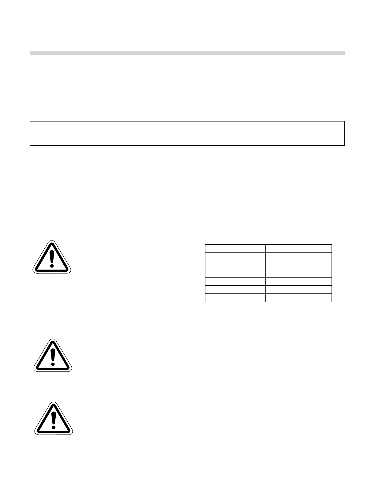
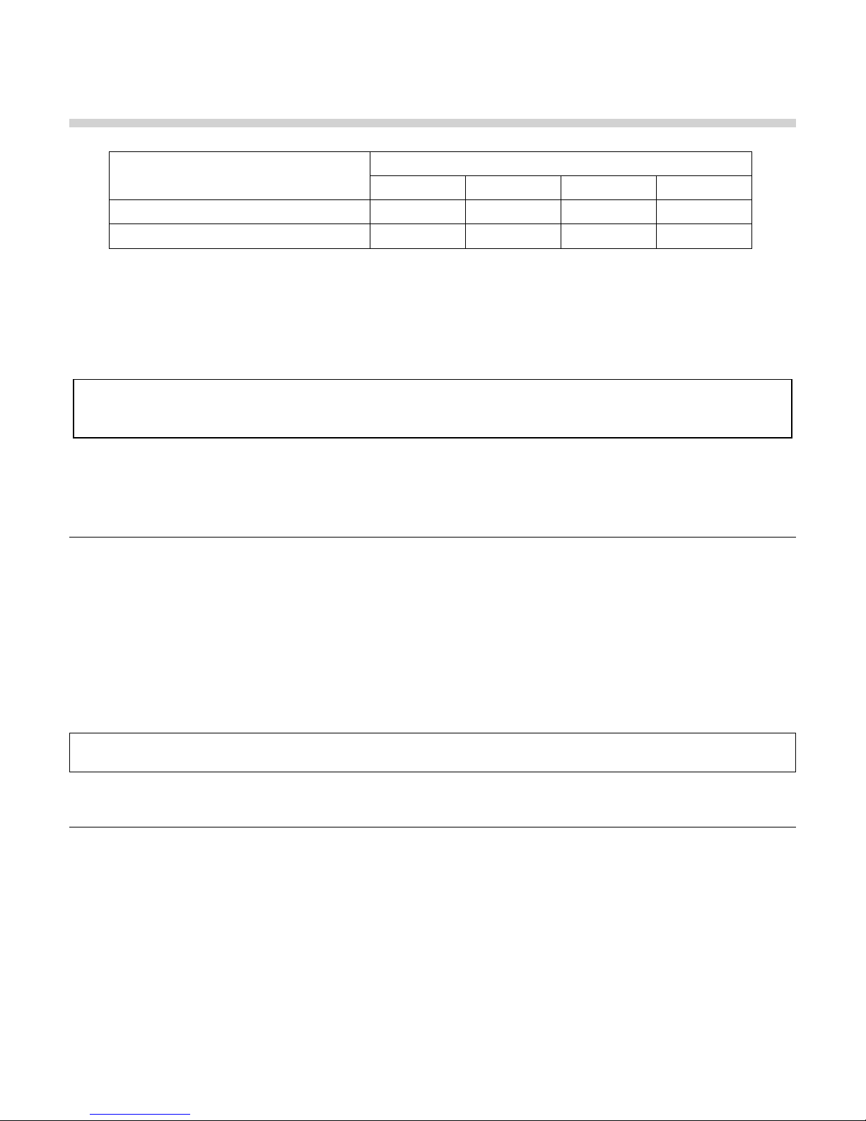
2.5.3 Crush Hazards
Lifting hazards! Use properly rated
lifting equipment to lift and position
the boiler. The load is unbalanced.
General Warning
Test balance before lifting 3 ft. above
the floor. Do not allow personnel beneath the lifted
load. Refer to approximate weights in the table at
right:
Boiler Size Weight in Pounds
700,000 Btu 595
1,000,000 Btu 595
1,200,000 Btu 685
1,500,000 Btu 985
1,700,000 Btu 990
2,000,000 Btu 1,025
Bump hazard from overhead piping. Install piping with adequate vertical clearance.
2.5.4 Chemical Hazards
Environmental hazard! The motorized gas valves may contain hydraulic oil. Use
safe procedures for the disposal of all lubricants.
Chemical hazards from cleaning products. Use caution when cleaning the system.
General Warning
The use of professional assistance is recommended. Use safe procedures for the
disposal of all cleaning solutions.
2.5.5 Pressure Hazards
Pressure hazard! Hot fluids. Install isolation valves on boiler water inlet and outlet.
Make sure isolation valves are closed before servicing boiler.
Pressure hazard! Hot fluids. Annually test safety relief valve for proper operation.
General Warning
Do not operate boiler with faulty relief valve.
8
P-K THERMIFIC
®
Gas-Fired Boiler
2.5.6 Slip, Fall Hazards
Tripping hazard! Do not install piping on floor surfaces. Maintain clear path around
boiler.
Slip and fall hazard! Use drip pan to catch water while draining the boiler. Maintain
dry floor surfaces.
General Warning
Slip and fall hazard! Do not locate intake or exhaust terminations directly above a
walkway; dripping of condensation can cause icing of the walking surface.
3 INSTALLATION
3.1 RECEIVING AND STORAGE
3.1.1 Initial Inspection
Upon receiving the boiler, inspect it for signs of shipping damage.
hidden, we recommend unpacking the boiler, removing the top and front covers to inspect the boiler.
Pay particular attention to the control panel on the top of the boiler and the components mounted on the
back, which may show damage from mishandling. Verify that the total number of pieces shown on the
packing slip agrees with those actually received.
Since some damage may be
NOTICE! Note any damage, suspected potential damage, or shortage of materials on the freight bill
and immediately notify the carrier. File all claims for shortage or damage with the carrier. Claims for
hidden damages must be filed with your carrier within 7 days. The boiler carton is equipped with a “Tip
(N) Tell”. If "Tip (N) Tell” arrow point is blue, that indicates that the package has been on its side or
tipped over in transit.
The exterior cabinet must be reasonably air-tight for the burner to operate correctly. Leaks caused by
dents in the sheet metal or panels out of position may cause the limit control to illuminate the Low Air
indicator light. Check to be sure that the mixer core in the top burner is centered and has not moved in
shipment (see Section 5.2 "Cleaning the Burner" for proper location).
3.1.2 Storage Prior to Installation
If the boiler is not installed immediately, it must be stored in a location adequately protected from the
weather, preferably indoors. If this is not possible, then it should remain in the shipping container and be
covered by a tarpaulin or other waterproof covering.
NOTICE! Controls and other equipment that are damaged or fail due to weather exposure are not covered by warranty.
3.2 C
OMPLIANCE WITH CODES
The P-K THERMIFIC® boiler with standard components and many options complies with American
National Standard/CSA Standard ANSI Z21.13/CSA 4.9, Gas-Fired Low Pressure Steam and Hot Water
Boilers, latest edition.
The heat exchanger is constructed and stamped in accordance with ASME Boiler and Pressure Vessel
Code, Section IV for 160 psig maximum operating pressure and/or 250º F maximum operating
temperature.
9

P-K THERMIFIC
®
Gas-Fired Boiler
Installation of the boiler must conform to all the requirements of all national, state and local codes
established by the authorities having jurisdiction or, in the absence of such requirements, in the U.S. to
the National Fuel Gas Code, ANSI Z223.1/NFPA 54, latest edition. In Canada, the equipment shall be
installed in accordance with the current Installation Code for Gas Burning Appliances and Equipment,
CAN/CGA-B.149, and applicable Provincial Regulations, which should be carefully followed in all cases.
Authorities having jurisdiction should be consulted before installations are made.
Where required by local codes, the installation must conform to American Society of Mechanical
Engineers Safety Code for Controls and Safety Devices for Automatically Fired Boilers (ASME CSD-1).
In the Commonwealth of Massachusetts, see Massachusetts Installation & Owner’s Manual Supplement.
3.3 S
3.3.1 Foundation
Provide a firm, level foundation, preferably of concrete.
NOTICE! The boiler may be installed on a combustible floor; however,
the boiler must never be installed on carpeting.
3.3.2 Placement
ETUP
The boiler must be level to function properly. To assist in leveling the
boiler, the four (4) leg bolts (1/2"- 13 NC) holding the boiler to the shipping
skid must be reinstalled in the threaded legs on the bottom. The
adjustable legs are also necessary to provide adequate floor clearance
and prevent distortion of the cabinet, (twisting, etc.) in addition to leveling.
Adjustable Legs for Leveling and Floor Clearance
3.3.3 Clearances
If the boiler is to be installed near combustible surfaces, the minimum clearances shown in the table
below must be maintained. Failure to provide for the service access clearances, even with noncombustible surfaces, may cause future problems servicing the boiler. The boiler must be installed in a
space large in comparison to the boiler as described in Section 6.3 of the National Fuel Gas Code, ANSI
Z223.1, latest edition.
DD
Minimum Clearances from Adjacent Walls, Ceiling, and Obstructions
10
P-K THERMIFIC
®
Gas-Fired Boiler
Type of Surface Dimensions (inches)
A B C† D
Combustible Surfaces 30 24* 30 24
Recommended Service Clearance 30 24 30 24**
† "C" dimension includes clearance to remove the burner. Do not put pipes, ducts, etc. in this area above the boiler.
* CSA minimum. Actual clearance depends upon venting requirements.
** Service access need be only on one side of a boiler or row of boilers.
Boilers may be installed immediately adjacent to each other. However, Harsco Industrial, PattersonKelley recommends this clearance between each boiler when there is insufficient access at the rear to
allow for service and adjustment.
Bumping hazard from overhead ducts! Install all components with adequate
vertical clearances.
In Canada: The boilers are approved for installation with zero clearance to combustible surfaces, but 24
inch service clearances are recommended.
3.4 E
LECTRICAL CONNECTIONS
The boiler is wired for 120 volts, single phase, 60 hertz. The electrical connections should be made in
the junction box on the rear of the boiler. The total operating amperage is indicated on the rating
nameplate. The 700 and 1000 series require less than 8 amps; while the 1500, 1700, 2000 series
requires less than 12 amps. Before starting the boiler, check to ensure that the proper voltage and
amperage is connected to the boiler.
An external electrical disconnect (not supplied with the boiler) with adequate overload protection is
required. The boiler must be grounded in accordance with local codes or in the absence of such
requirements, in the U.S. with National Electrical Codes, ANSI/NFPA No. 70, latest edition and in
Canada, wire according to the current Canadian Electrical Code, Part I, CSA C22.1.
NOTICE! A dedicated earth ground (green wire) is required to avoid nuisance shutdowns. Do not
ground through the conduit. It is also important that proper polarity be maintained.
3.5 I
NLET AIR AND EXHAUST VENTING
3.5.1 Applicable Codes & Standards
CODES
United States:
NFPA 54/ANSI Z223.1 National Fuel Gas Code
NFPA/ANSI 211 Chimneys, Fireplaces, Vents and Solid Fuel Burning Appliances
Canada
CAN/CSA B149.1 Installation Codes for Gas Burning Equipment
STANDARDS
11

P-K THERMIFIC
®
Gas-Fired Boiler
UL CUL 441 Type B Gas Vent (Category I)
These codes and standards contain information for the venting of gas fired appliances, including, but not
limited to vent sizing, location, clearance to combustibles, and safe installation practices. The installation
must comply with all applicable national, state, provincial and local codes.
Design and installation of venting systems should be done only by qualified
and knowledgeable venting systems personnel and in accordance with vent system manufacturer’s
installation instructions. Installing a boiler or vent system using improper installation methods or
materials can result in serious injury or death due to fire or asphyxiation.
Before connecting a boiler to a venting system, it must be determined whether the boiler is to be
installed in a conventional or Direct Vent configuration
Use of imp roper vent material may result in rapid deterioration of the venting
system. Improper vent installations may allow toxic fumes to be released into the living area. This may
cause property damage, serious bodily injury or death.
NOTICE! Failure to use a proper vent system (types and materials), as described in this manual may
void the boiler warranty.
3.5.1.1 Gas Vent Categories
Several codes and standards have categorized appliances in accordance with the flue gas temperature
and pressure produced by the appliance. Categories are defined as follows:
Category I An appliance that operates with a non-positive vent static pressure and with a vent
temperature that avoids excessive condensate production in the vent.
Category II An appliance that operates with a non-positive vent static pressure and with a vent
temperature that may cause excessive condensate production in the vent.
Category III An appliance that operates with a positive vent static pressure and with a vent tem-
perature that avoids excessive condensate production in the vent.
Category IV An appliance that operates with a positive vent static pressure and with a vent tem-
perature that may cause excessive condensate production in the vent.
Direct Vent An appliance that is constructed and installed so that all air for combustion is derived
directly from outdoors and all flue gases are discharged to the outdoors.
3.5.1.2 Venting Materials for Flue/Exhaust Systems
P-K THERMIFIC® boilers are Category I appliances, as it is defined in NFPA 54/ANSI Z223.1. The P-K
THERMIFIC
®
boiler may be vented in accordance with NFPA 54/ANSI Z223.1. Venting material may
include Type “B” gas vent, chimney, single-wall metal pipe, listed chimney lining system for gas venting,
or special gas vent listed for Category I appliances.
Use of plastic vent will result in vent failure and may cause serious injury or
death. This boiler is not suitable for use with any type of plastic or non-metallic venting.
In Canada, the boiler is certified for installation with a "Power Venter" by the Canadian Gas Association
when installed with the "listed accessories." Consult your local distributor for information on proper
selection.
12
P-K THERMIFIC
®
Gas-Fired Boiler
The venting materials listed below are intended for the venting of gas burning
appliances only. Do not use these venting materials for venting liquid or solid fuel (such as oil,
kerosene, wood or coal) appliances
Maintain clearances to combustibles as listed in the vent manufacturer’s installation instructions or as
set forth in the codes and standards listed in this section.
Do not use these vent pipes for incinerators of any sort.
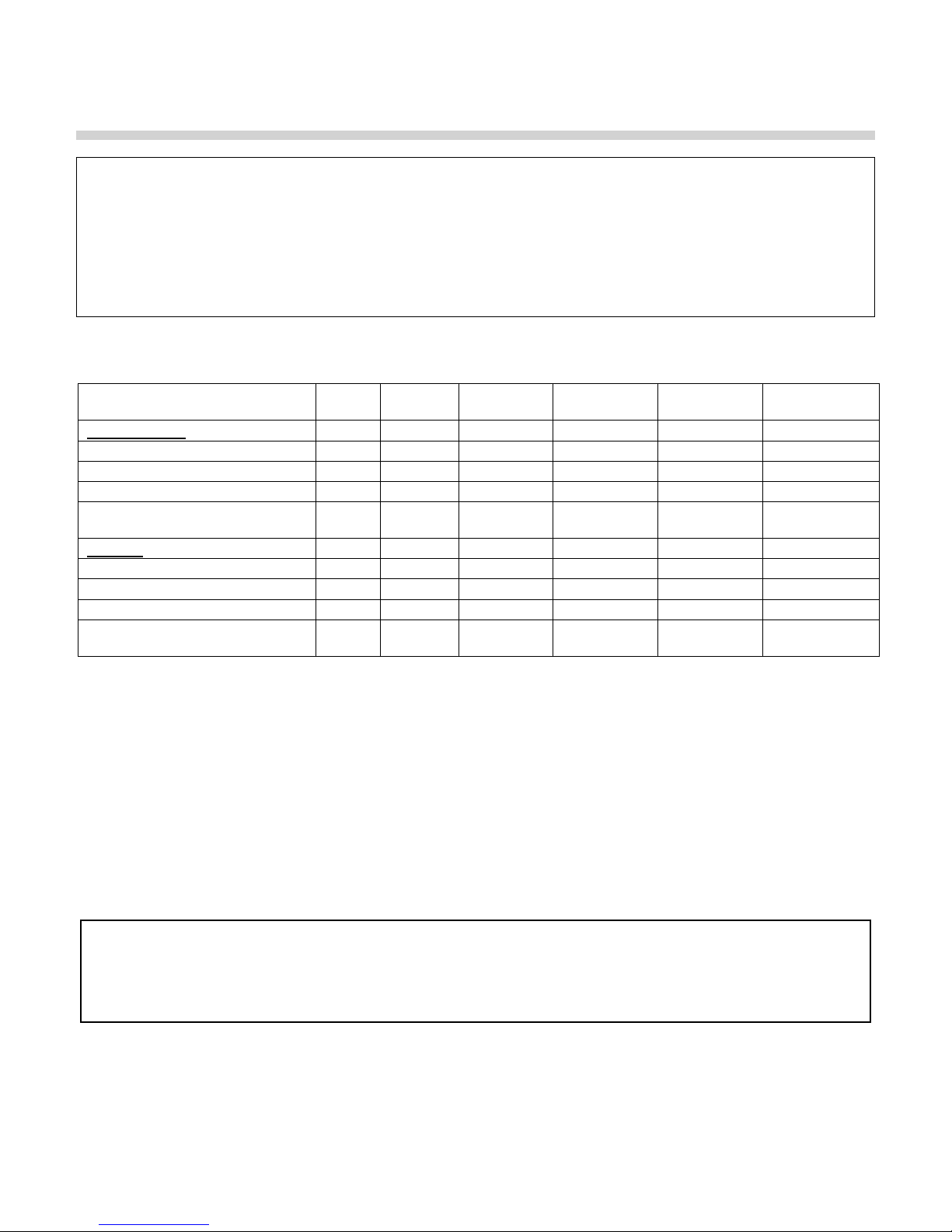
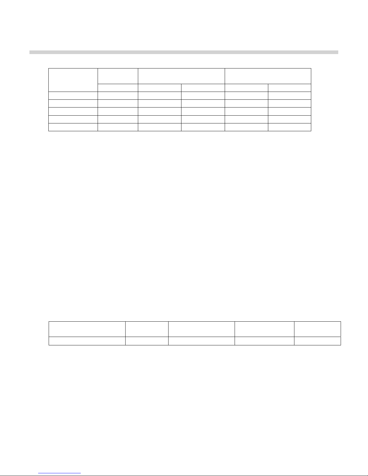
Table of Applicable Vent Materials by P-K THERMIFIC
Model B-Vent Chimney
United States
N700-N1000 X X X X X
N1500-N2000 On-Off X X X X X
N1500-N2000 LHL X X X X X
N700-N2000 Sealed Combus-
tion
Canada
N700-N1000 X X X X X
N1500-N2000 On-Off X X X X X
N1500-N2000 LHL X X X X X
N700-N2000 Sealed Combus-
tion
No No No No No X
No No No No No X
®
Boiler Model
Single Wall
Metal Pipe
Listed Gas
Vent System
Special Gas
Vent System
UL 1738 listed
Cat II/III/IV
3.5.2 Combustion Air
Combustion air must be free from dust, lint, etc. The presence of such materials in the air supplied to the
burner could cause nuisance "Low Air" shutdowns or premature burner failure. The boiler should not be
operated during construction while the possibility of drywall dust, demolition dust, etc. exists.
The combustion air supply must be completely free of chemical fumes which may be corrosive when
burned in the boiler. Common chemicals which must be avoided are fluorocarbons and other
halogenated compounds, most commonly present as refrigerants or solvents, such as freon,
trichloroethylene, perchloroethylene, chlorine, etc. These chemicals, when burned, form acids which
quickly attack the boiler and the boiler stack. The result is improper combustion and premature boiler
failure.
Under no circumstances shall the boiler room ever be under a negative
pressure. Particular care should be taken when exhaust fans, compressors, air-handling units or other
equipment may rob air from the boiler. Note that this equipment might be in rooms other than the boiler
room.
3.5.2.1 Air Inlet Requirements – United States (NFPA 54/ANSI Z223.1 & NFPA/ANSI 211)
When air is supplied from inside the building, the total required volume shall be the sum of the required
volume for all the appliances located in the mechanical room. Adjacent rooms furnished with fixed
openings communicating directly with the mechanical room are considered part of the required volume.
The minimum volume is 50 ft
3
per 1000 Btu/hr (4.8 m3/kW) of installed appliance input capacity.
13
P-K THERMIFIC
®
Gas-Fired Boiler
Openings used to connect indoor spaces to obtain the required minimum volume shall be sized as
follows:
When rooms are on the same floor, each opening shall have an area equal to 1 square inch for each
1000 Btu/hr (2200 mm
inches. One opening should commence less than 12 inches above the floor and the other less than
12 inches below the ceiling. The minimum dimension of air openings shall be 3 inches.
When rooms are on different floors, each opening shall have an area equal to 2 square inches for
each 1000 Btu/hr (4400 mm
When combustion air is supplied from outside the building, the boiler room shall be provided with one or
two openings to ensure adequate combustion air and proper ventilation.
When using one permanent opening, the opening shall commence within 12 inches of the ceiling and
shall communicate directly with the outdoors or through a vertical or horizontal duct that communicates to
the outdoors.
Minimum free area of the opening is 1 square inch for each 3000 Btu/hr (700 mm
appliance input capacity, and
Not less than the sum of the areas of all vent connectors in the room.
When using two permanent openings, one opening shall commence within 12 inches above the floor and
the other within 12 inches below the ceiling, preferably on opposite walls. The openings shall
communicate directly, or by way of ducts, with free outdoor air. The minimum net free area of the
openings shall be calculated in accordance with the following:
2
/ kW) of installed appliance input capacity, but not less than 100 square
2
/ kW) of installed appliance input capacity.
2
/ kW) of installed
When air is taken directly from outside the building, each opening (minimum of two, as outlined
above), 1 square inch for each 4,000 Btu per hour (550 mm
When air is taken from the outdoors through a vertical duct into the mechanical room, 1 square inch
per 4,000 Btu per hour (550 mm
When air is taken from the outdoors through a horizontal duct into the mechanical room, 1 square
inch per 2,000 Btu per hour (1100 mm
NOTICE!
2
/kW) of total boiler input is required.
2
/kW) of total boiler input is required.
2
/kW) of total boiler input is required.
1.The required size of openings for combustion and ventilation air shall be based on the net free area of
the opening.
2.Screens shall be not smaller than ¼”
3.Motorized louvers shall be interlocked with the appliance so that they are proven open prior to main
burner ignition and operation.
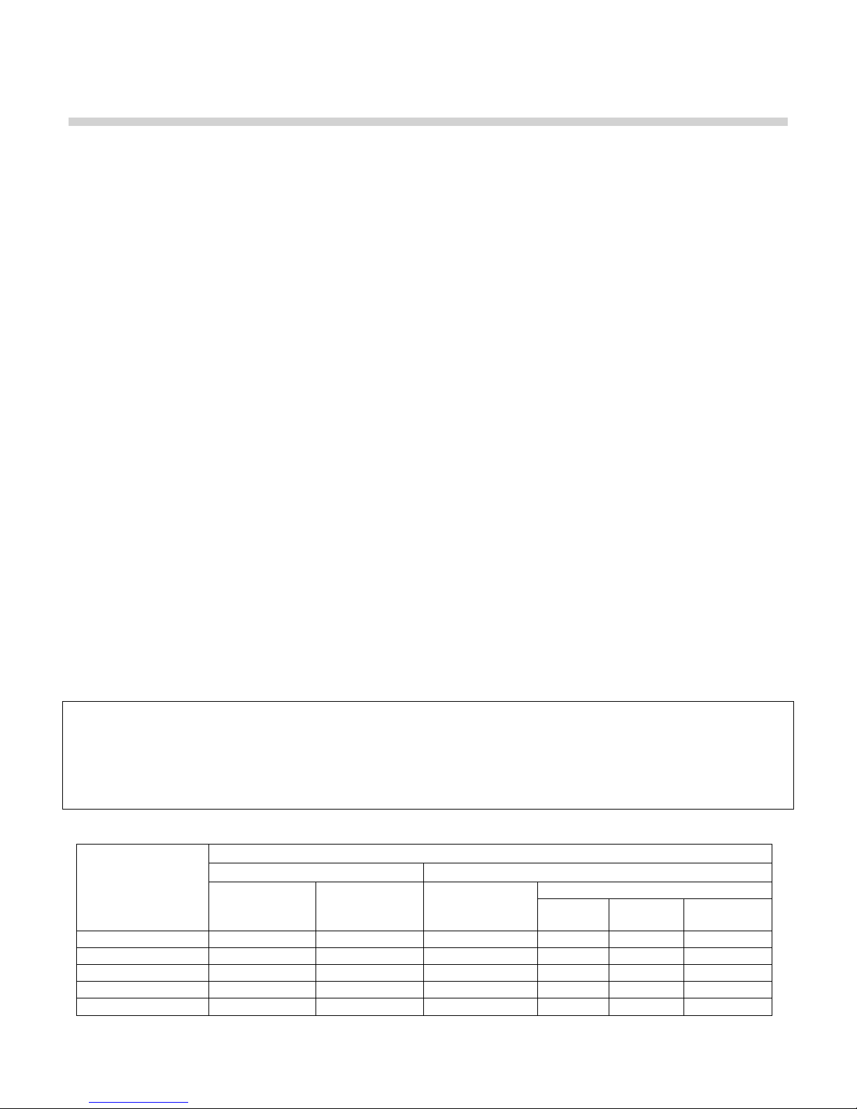
Table of US Minimum area of ventilation openings per boiler (sq inches)
AIR SOURCE
INDOOR AIR SUPPLY OUTDOOR AIR SUPPLY
®
SAME FLOOR DIFF FLOORS ONE OPENING
P-K THERMIFIC
MODEL
N700 700 1400 234 175 175 350
N1000 1000 2000 333 250 250 500
N1500 1500 3000 500 375 375 750
N1700 1700 3400 567 425 425 850
N2000 2000 4000 668 500 500 1000
DIRECT
TWO OPENINGS
VERT
DUCT
HORIZ
DUCT
14

P-K THERMIFIC
®
Gas-Fired Boiler
3.5.2.2 Air Inlet Requirements – Canada (CAN/CSA B149.1)
A. Ventilation of the space occupied by fuel burning appliance(s) or equipment shall be supplied by a
ventilation opening at the highest practicable point communicating with the outdoors. The total cross
sectional area of the ventilation opening must be either 10% of the net free area required for
combustion air or 10 sq. in. (6500 mm
B. Use the following opening calculation for MACH
boilers:
When combustion air is supplied for a forced draft burner by natural airflow from the outdoors and
there is no draft regulator or draft hood in the same space, there shall be a permanent opening with a
cross sectional area not less than 1 sq. in/ 30,000 Btu/Hr (70 mm
burner(s). This opening must not interfere with the ventilation air opening defined in paragraph A.
C. Use the following opening calculation for P-K THERMIFIC
appliances:
When combustion air is supplied for natural or fan-assisted burners by natural airflow from the
outdoors, there shall be a permanent opening with a cross sectional area not less than 1 sq. in/ 7000
Btu/Hr (321 mm
2
mm
/kW) in excess 1,000,000 Btu/Hr. This opening must be either located at or ducted to a point not
2
/kW) up to and including 1,000,000 Btu/Hr plus 1 sq. in. / 14,000 Btu/Hr (155
more than 18 in. (450 mm) or less than 6 in. (150 mm) above floor level. This opening is in addition
to the ventilation air opening defined in paragraph A.
2
), whichever is greater.
®
condensing boilers or MODU-FIRE® Forced Draft
®
boilers or other natural draft or fan-assist
2
/kW) of the total rated input to the
D. When combustion air is supplied by natural airflow into a space containing both types of appliance
described in paragraphs B and C, the cross sectional area of the opening shall be not less than the
sum of the cross sectional areas for all appliances in the space as calculated by the applicable
method . This opening is in addition to the ventilation air opening defined in paragraph A.
E. When a duct is used to meet the requirement for combustion air supply, as described in paragraphs
A through D, above, the opening of the duct shall be located so there is no possibility of cold air
affecting steam or water piping, electrical equipment or mechanical equipment.
F. When combustion air is supplied by mechanical means, an airflow-sensing device must be installed.
It must be wired into the pre-ignition limit string to prevent the burner from starting or to stop an
operating burner in case of air supply failure.
G. When all combustion air is supplied through a make-up air heater, and the appliance is interlocked to
the heater, the requirements of paragraphs A through F do not apply.
NOTICE!
1. The free area of a combustion air supply opening is calculated by deducting the blockage area of any
fixed louvers, grilles or screens from the total area of the opening.
2. Screens shall be not smaller than ¼”
3. Motorized louvers shall be interlocked with the appliance so that they are proven open prior to main
burner ignition and operation
15
P-K THERMIFIC
®
Gas-Fired Boiler
Table of Canadian Minimum Area of Combustion and Ventilation Air Openings
P-K
THERMIFIC
Model #
®
Input
Btu/Hr in2 mm2 in2 mm2
N700 700,000 100 64,516 10 6,452
N1000 1,000,000 143 92,257 14.3 9,226
N1500 1,500,000 179 115,484 17.9 11,548
N1700 1,700,000 193 124,516 19.3 12,452
N2000 2,000,000 214 138,064 21.4 13,806
3.5.3 Flue Venting
P-K THERMIFIC
The P-K THERMIFIC
®
boilers are Category I appliances, as defined in ANSI Z21.13/CSA 4.9, latest edition.
®
boiler may be vented with any venting systems meeting the requirements of
Category I venting systems as specified in the latest edition of NFPA 54/ANSI Z223.1 in the US or the
latest edition of CAN/CSA B-149.1 in Canada.
This boiler is suitable for use with Type "B" vent.
The exhaust vent can be run horizontally or vertically.
Vent installations shall be in accordance with NFPA54/ANSI Z223.1, the National Fuel Gas Code, or
CAN/CSA-B149.1, the Natural Gas and Propane Installation Code, or applicable provisions of the local
building codes.
Required Combustion Air
Opening
Ventilation Air Opening
If the boiler is installed using sealed combustion / direct vent, see Section 3.5.5.
3.5.3.1 Vent Sizing
The vent must be sized in accordance with the ASHRAE Systems and Equipment handbook, Chapter 30
or according to the vent manufacturer’s recommendations. When using manufactured venting systems,
consult your vent supplier for correct sizing and structural support requirements. Vent diameter is
dictated by the length and height of horizontal and vertical portions of the vent installation and materials
of construction.
Table of Vent Design Parameters
P-K THERMIFIC® Mod-
el
Stack Draft Stack Temperature CO
Natural Gas CO2 LP Gas
2
N700-N2000 -0.04” 325°F 7.6% 8.9%
Design calculations should be based on a negative 0.04” W.C. with a stack temperature of 325º F (gross)
and a CO
level of 7.6%; (these values are to be used for vent sizing calculations.) The maximum
2
allowable length of the vent duct, including the boot tee/135º tee (not a standard tee) and the termination
is 100 equivalent feet. See the table below for the equivalent length of fittings used in the venting system
16
P-K THERMIFIC
®
Gas-Fired Boiler
Approximate Equivalent Length of Fittings
Fitting Description Equivalent Length
90º Elbow 10 feet
45º Elbow 5 feet
Rain Cap* 10 feet
Open Termination 10 feet
Boot Tee/135º Tee 10 feet
Standard Tee used as a Vent Termination 10 feet
* Low loss rain cap (see illustration in Section 3.5.3.5)
3.5.3.2 Exhaust Vent Connection at the Boiler
The connection from the boiler to the vent should be as direct as possible and the upward slope of any
horizontal breeching should be at least 1/4 inch per linear foot. This boiler should not be connected into
any portion of a mechanical draft system operating under positive pressure. Provisions must be made to
maintain required clearances to combustibles.
NOTICE! The collar is not designed to support the weight of the vent. Assure that the weight of the
vent is not supported by the boiler vent collar.
NOTICE! If using manufactured vent, assure that it is supported in accordance with the vent
manufacturer's requirements.
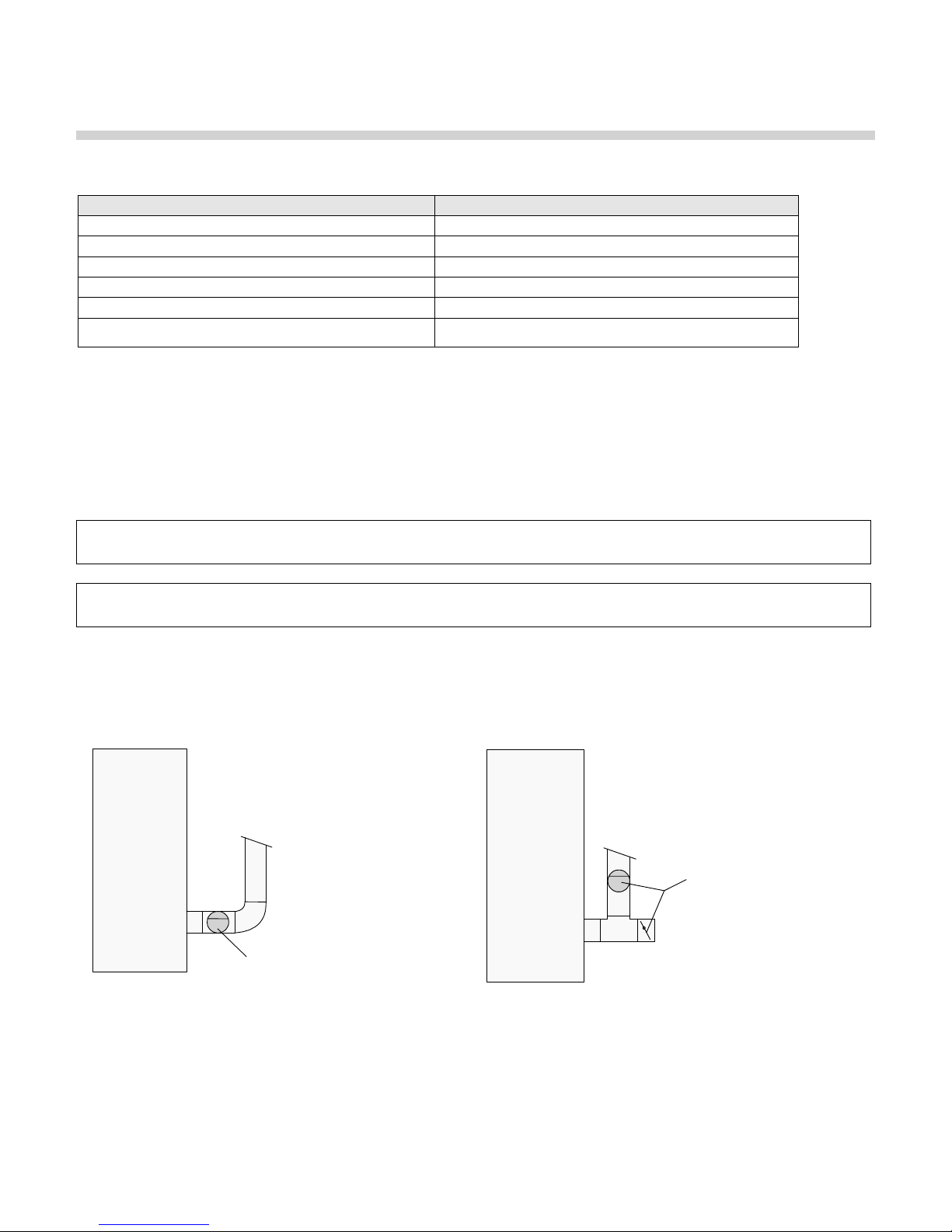
3.5.3.3 Barometric Damper
Venting installations may require a barometric damper for smooth operation. A barometric damper is
supplied with each boiler, and when used, should be installed according to the following guidelines.
Boiler
Barometric
Damper
Boiler
Barometric
Damper,
(
incorrect
locations)
Correct Damper Location Incorrect Damper Locations
1. The barometric damper must be located immediately after the flue connector (left drawing above).
2. The damper may be located in either the left or right side of the horizontal section of stack.
3. In a multiple boiler installation, one barometric damper must be installed with each boiler.
17
(
)
P-K THERMIFIC
®
Gas-Fired Boiler
Be sure that the damper is mounted horizontally (never vertically). Be sure to remove all three red stops
from the damper before start-up. The damper door should swing freely. Carefully follow all the
instructions provided with the barometric damper.
To avoid spillage into the boiler room of dangerous flue gas containing carbon
monoxide, the opening in the damper (draft control gate) must never face against the flow of flue gas.
3.5.3.4 Horizontal to Vertical Transitions
The turn from horizontal to vertical should be made with two 45º ells, a long radius 90º ell, or a 135° boot
tee. Do not use "short radius" ells.
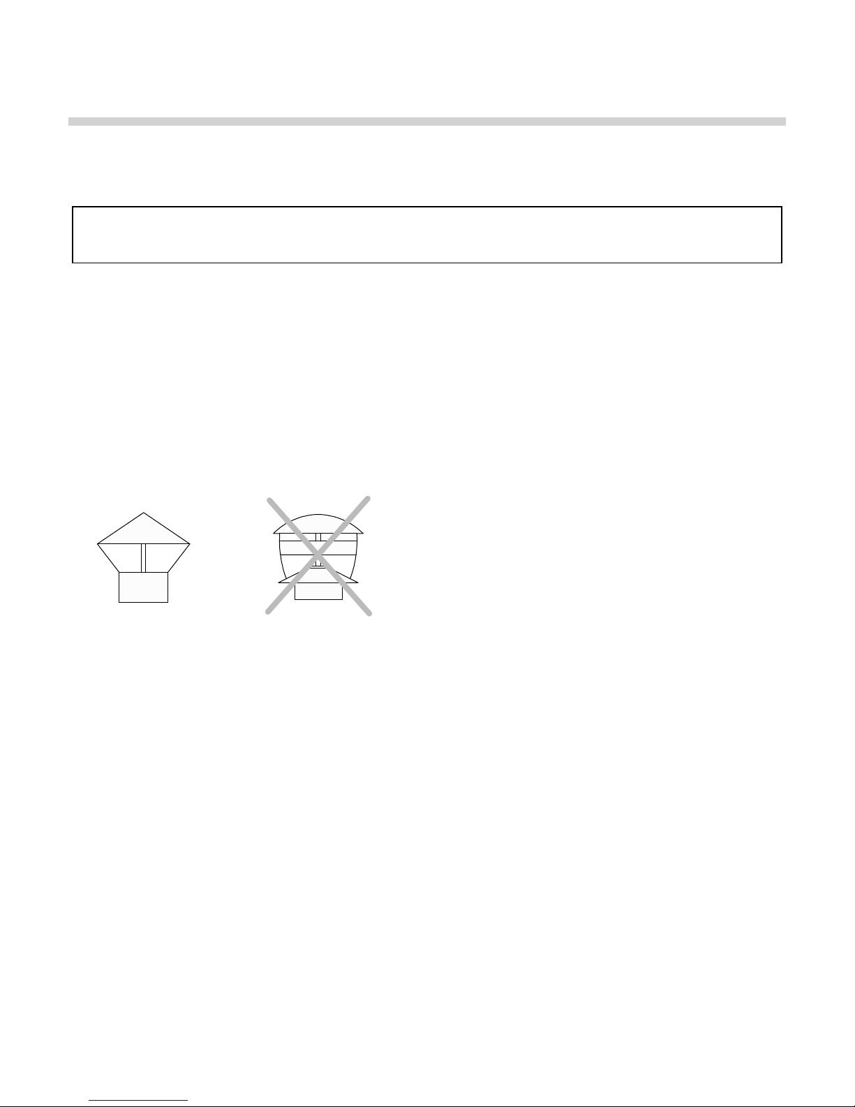
3.5.3.5 Vent Termination
The vent may be terminated with either no cap or a low-loss (non-restrictive) cap of adequate capacity.
The cap must be approved by the vent manufacturer for use with their product.
Correct Listed
Termination
Incorrect
Termination
too restrictive
3.5.3.6 Required Clearances
The vent must extend at least three (3) feet above the roof, or at least two (2) feet above the highest part
of any structure within ten (10) feet of the vent (see diagram below):
Reference: NFPA 54/ANSI Z223.1
National Fuel Gas Code
18

P-K THERMIFIC
®
Gas-Fired Boiler
To prevent the possible re-circulation of flue gases, the vent designer must take into consideration such
things as prevailing winds, eddy zones, building configurations, etc. Harsco Industrial, Patterson-Kelley
cannot be responsible for the effects such adverse conditions may have on the operation of the boilers.
Dimensions listed above are minimums and may not be sufficient for conditions at a specific job site.
Provide clearances between combustion air intake, exhaust vent, roof and wall surfaces, doors and
window as illustrated below. Also, provide clearances at least 2 feet above the expected snow line.
Exit Terminals of Mechanical Draft and Direct Vent Venting Systems
Reference: NFPA 54/ANSI Z223.1 National Fuel Gas Code
3.5.4 Fresh Air System (Ducted Combustion Air)
In some instances compliance with ANSI Z21.13 may not be required, in which case a "fresh air system"
may be used. Consultation with qualified professionals is required to determine whether a "fresh air
system" is suitable for any particular application and in compliance with all applicable codes and
regulations.
All flue gas outlet (exhaust vent) material for a fresh air system must be certified for use with a Category I
Appliance. (Standard B-vent is approved.) The exhaust vent may be run horizontally or vertically. Proper
vent sizing by the vent manufacturer's recommendation must be followed.
3.5.5 Sealed Combustion/Direct Vent Systems
P-K THERMIFIC
®
boilers are certified for operation with a sealed combustion air inlet and a sealed non-
pressurized venting system. These models are designated by the prefixes SN or SD
19
P-K THERMIFIC
®
Gas-Fired Boiler
A sealed combustion system employs an air intake duct leading directly from outdoors to the boiler and
an exhaust vent terminating outdoors. Air flow through the system is maintained by the combustion air
fan and the stack draft. An exhaust fan is not required.
3.5.5.1 Sealed Combustion Intake Duct Materials and Sizes
The air intake duct can be fabricated from PVC, CPVC, single wall galvanized steel, or other suitable
materials. The duct must be rigid enough to maintain the full required cross sectional area under all
operating conditions. Proper sealing of the intake ductwork is necessary to prevent infiltration of air from
conditioned space. Joints in PVC or CPVC must be cemented. For galvanized duct, wrap each joint and
seam with adhesive aluminum tape or other sealant. Connect the air supply duct to the inlet air collar on
the boiler. Securely fasten and seal the duct to the collar. The installation of a bird screen on the intake
termination is recommended. Ensure that the screen does not become blocked with snow, ice, insects
etc.
3.5.5.2 Sealed Combustion System Design - Pressure Drop
The air inlet duct system shall be designed for a maximum pressure drop of 0.05" W.C. at the given air
flow, taking into account the equivalent length of all fittings. The equivalent length method is ONLY for
use with a single boiler system. For multiple boiler systems, the air inlet duct system must be designed
by a qualified ventilation professional.
Combustion Air Requirement, SCFM Equivalent Length of Fittings
Series
700
170 251 364 413 501
Series
1000
Series
1500
Series
1700
Series
2000
Fitting Description Equivalent Length
90º Elbow 10 feet
45º Elbow 5 feet
Air Intake 10 feet
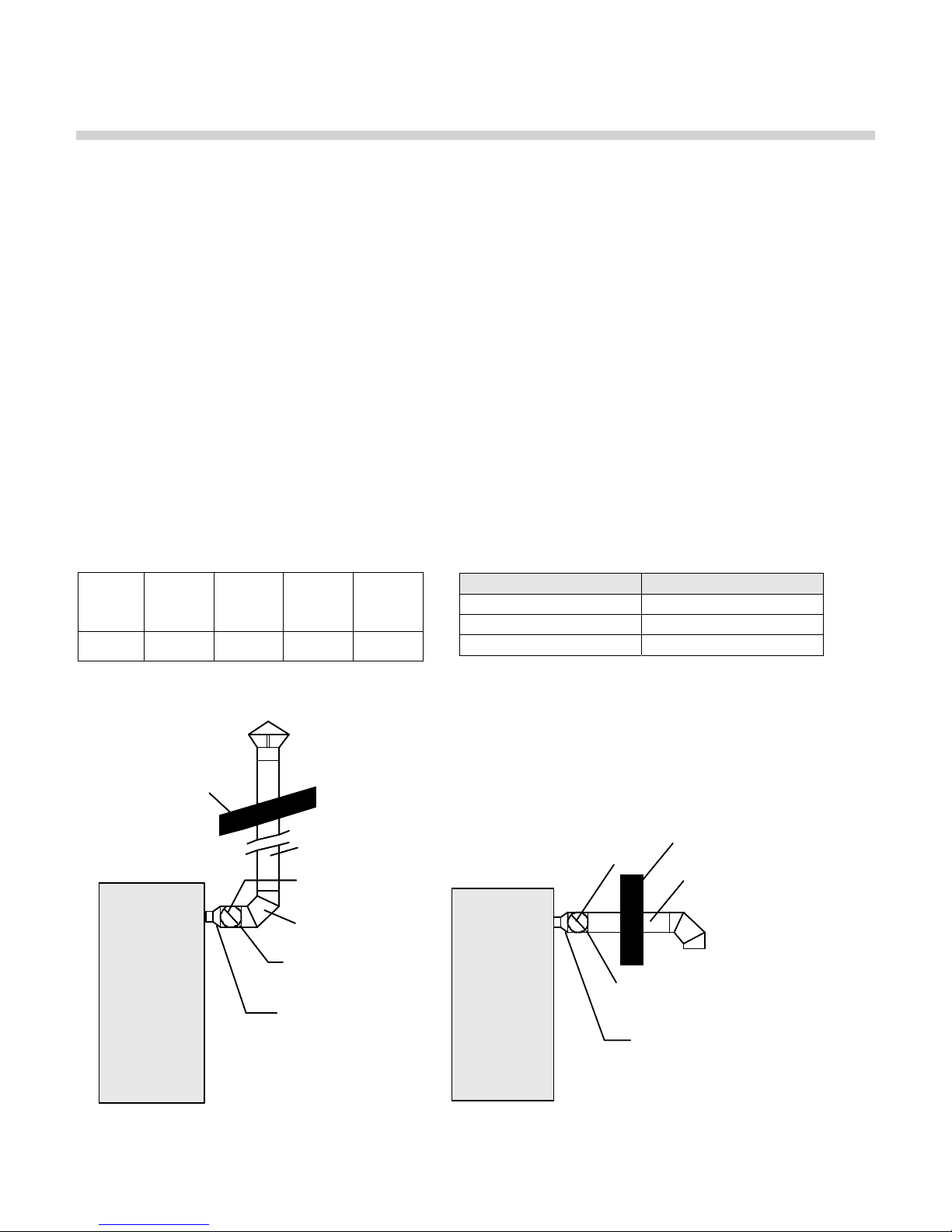
3.5.5.3 Sealed Combustion Inlet Duct Assembly at the Boiler
Roof
Roof
Round
Round
Damper
Damper
o
o
90 Elbow
90 Elbow
Damper
Damper
Housing
Housing
Transition
Transition
Duct
Duct
Damper
Damper
Damper
Damper
Housing
Housing
Transition
Transition
Duct
Duct
Wall
Wall
Round
Round
Roof installation shown Sidewall installation shown
20
 Loading...